Page 28 of 4087
Location of Connectors in Engine Compartment
wLocation of connectors
This diagram shows the wire harnesses and connectors used in one system.\
The connector shows the harness side connector, so when checking the part side connector (sensor, ac-
tuator, etc.), be careful not to mistake the terminal positions.
±
INTRODUCTION How to Troubleshoot ECU Controlled SystemsIN±25
WhereEverybodyKnowsYourName
Page 552 of 4087
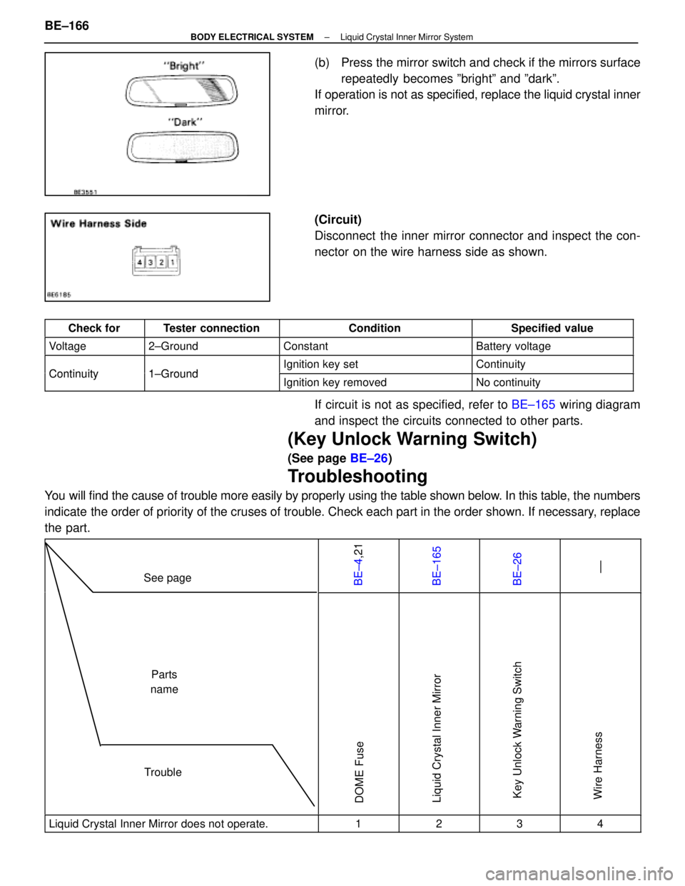
(b) Press the mirror switch and check if the mirrors surfacerepeatedly becomes ºbrightº and ºdarkº.
If operation is not as specified, replace the liquid crystal inner
mirror.
(Circuit)
Disconnect the inner mirror connector and inspect the con-
nector on the wire harness side as shown.
Check forTester connectionConditionSpecified value
Voltage2±GroundConstantBattery voltage
Continuity1 GroundIgnition key setContinuityContinuity1±GroundIgnition key removedNo continuity
If circuit is not as specified, refer to BE±165 wiring diagram
and inspect the circuits connected to other parts.
(Key Unlock Warning Switch)
(See page BE±26)
Troubleshooting
You will find the cause of trouble more easily by properly using the table \
shown below. In this table, the numbers
indicate the order of priority of the cruses of trouble. Check each part in the \
order shown. If necessary, replace
the part.
See pageBE±4,21BE±165BE±26 ±±
TroubleParts
name
DOME FuseLiquid Crystal Inner MirrorKey Unlock Warning SwitchWire Harness
Liquid Crystal Inner Mirror does not operate.1234
BE±166±
BODY ELECTRICAL SYSTEM Liquid Crystal Inner Mirror System
WhereEverybodyKnowsYourName
Page 593 of 4087
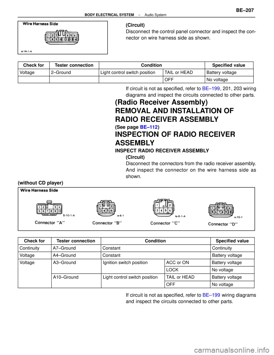
(Circuit)
Disconnect the control panel connector and inspect the con-
nector on wire harness side as shown.
Check forTester connectionConditionSpecified value
Voltage2±GroundLight control switch positionTAIL or HEADBattery voltage
OFFNo voltage
If circuit is not as specified, refer to BE±199, 201, 203 wiring
diagrams and inspect the circuits connected to other parts.
(Radio Receiver Assembly)
REMOVAL AND INSTALLATION OF
RADIO RECEIVER ASSEMBLY
(See page BE±112)
INSPECTION OF RADIO RECEIVER
ASSEMBLY
INSPECT RADIO RECEIVER ASSEMBLY
(Circuit)
Disconnect the connectors from the radio receiver assembly.
And inspect the connector on the wire harness side as
shown.
(without CD player)
Check forTester connectionConditionSpecified value
ContinuityA7±GroundConstantContinuity
VoltageA4±GroundConstantBattery voltage
VoltageA3±GroundIgnition switch positionACC or ONBattery voltageg
LOCKNo voltage
A10±GroundLight control switch positionTAIL or HEADBattery voltageg
OFFNo voltage
If circuit is not as specified, refer to BE±199 wiring diagrams
and inspect the circuits connected to other parts.
±
BODY ELECTRICAL SYSTEM Audio SystemBE±207
WhereEverybodyKnowsYourName
Page 596 of 4087
(c) Disconnect the connector and remove the wooferamplifier.
2. INSTALL WOOFER AMPLIFIER For installation, follow the removal procedure in reverse.
INSPECTION OF WOOFER AMPLIFIER
INSPECT WOOFER AMPLIFIER
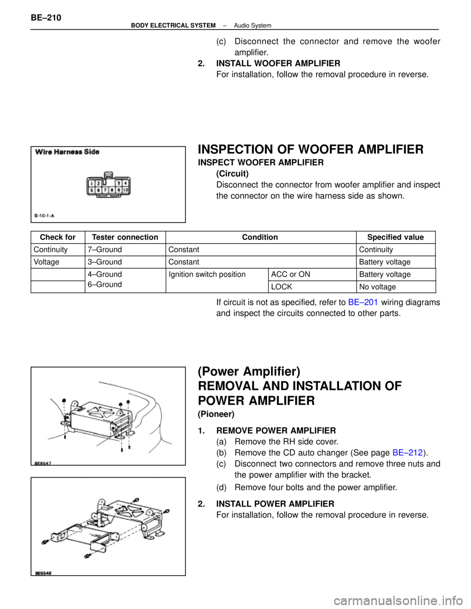
(Circuit)
Disconnect the connector from woofer amplifier and inspect
the connector on the wire harness side as shown.
Check forTester connectionConditionSpecified value
Continuity7±GroundConstantContinuity
Voltage3±GroundConstantBattery voltage
4±GroundIgnition switch positionACC or ONBattery voltage
6±Ground
g
LOCKNo voltage
If circuit is not as specified, refer to BE±201 wiring diagrams
and inspect the circuits connected to other parts.
(Power Amplifier)
REMOVAL AND INSTALLATION OF
POWER AMPLIFIER
(Pioneer)
1. REMOVE POWER AMPLIFIER (a) Remove the RH side cover.
(b) Remove the CD auto changer (See page BE±212).
(c) Disconnect two connectors and remove three nuts and the power amplifier with the bracket.
(d) Remove four bolts and the power amplifier.
2. INSTALL POWER AMPLIFIER For installation, follow the removal procedure in reverse.
BE±210
±
BODY ELECTRICAL SYSTEM Audio System
WhereEverybodyKnowsYourName
Page 597 of 4087
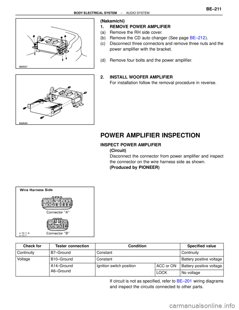
(Nakamichi)
1. REMOVE POWER AMPLIFIER
(a) Remove the RH side cover.
(b) Remove the CD auto changer (See page BE±212).
(c) Disconnect three connectors and remove three nuts and the power amplifier with the bracket.
(d) Remove four bolts and the power amplifier.
2. INSTALL WOOFER AMPLIFIER For installation follow the removal procedure in reverse.
POWER AMPLIFIER INSPECTION
INSPECT POWER AMPLIFIER
(Circuit)
Disconnect the connector from power amplifier and inspect
the connector on the wire harness side as shown.
(Produced by PIONEER)
������� �������Check for�������� ��������Tester connection��������������� ���������������Condition�������� ��������Specified value
������� �������Continuity�������� ��������B7±Ground��������������� ���������������Constant�������� ��������Continuity
������� �������Voltage�������� ��������B10±Ground��������������� ���������������Constant�������� ��������Battery positive voltage
������� ��������������� ��������A14±Ground
A6 G d
����������� �����������Ignition switch position����� �����ACC or ON�������� ��������Battery positive voltage������� ��������������� ��������A6±Ground����������� ���������������� �����LOCK�������� ��������No voltage
If circuit is not as specified, refer to BE±201 wiring diagrams
and inspect the circuits connected to other parts.
±
BODY ELECTRICAL SYSTEM AUDIO SYSTEMBE±211
WhereEverybodyKnowsYourName
Page 598 of 4087
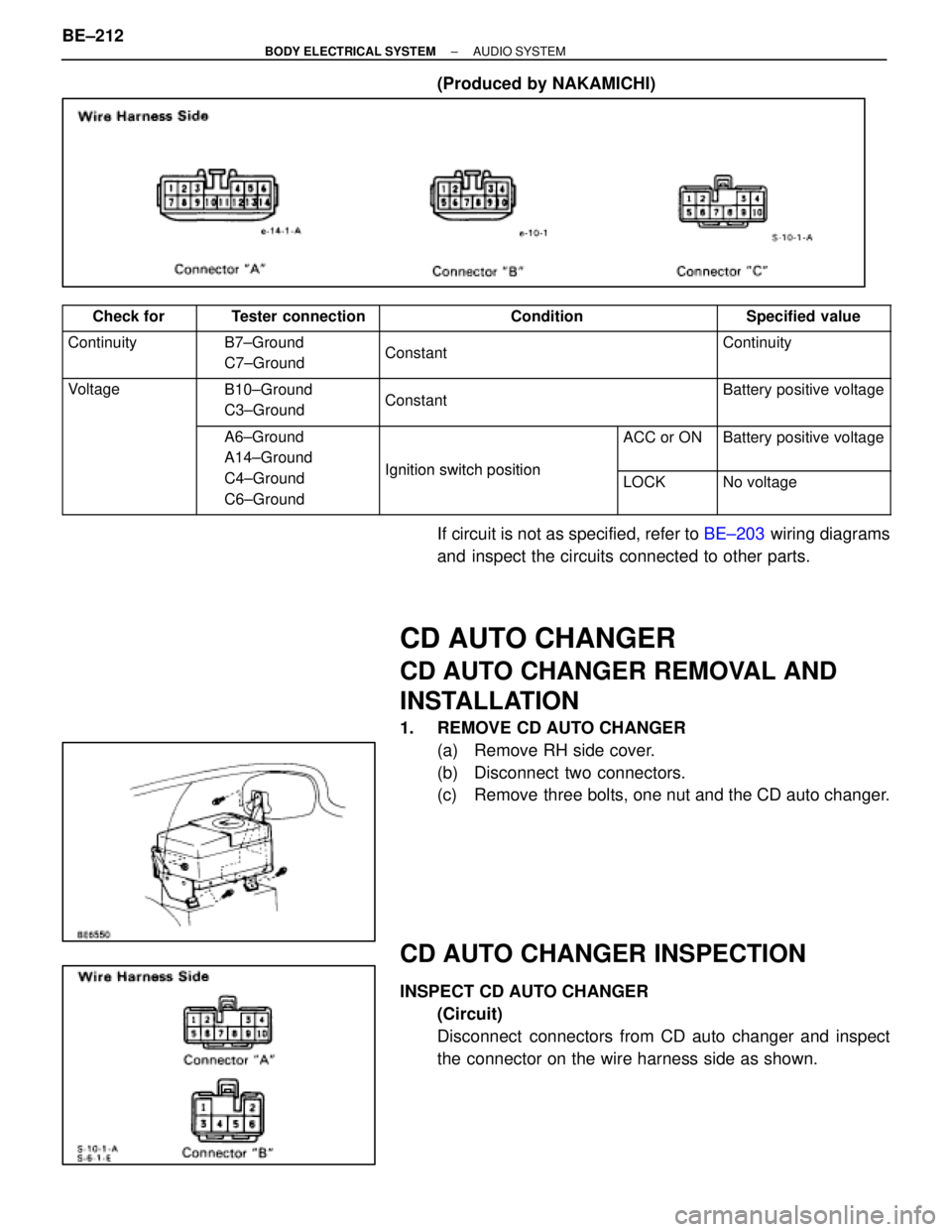
(Produced by NAKAMICHI)
������� �������Check for�������� ��������Tester connection��������������� ���������������Condition�������� ��������Specified value������� �
������
�������Continuity�������� �
�������
��������B7±Ground
C7±Ground��������������� �
��������������
���������������
Constant
��������
��������
��������Continuity
������� �
������
�������Voltage�������� �
�������
��������B10±Ground
C3±Ground��������������� �
��������������
���������������
Constant
��������
��������
��������Battery positive voltage
������� �
������
�������
�������� �
�������
��������A6±Ground
A14±Ground����������� �
����������
�����������
Ignition switchposition
����� �
����
�����
ACC or ON��������
��������
��������Battery positive voltage
������� �
������
�������
�������� �
�������
��������
C4±Ground
C6±Ground����������� �
����������
�����������
Ignition switch position����� �
����
�����
LOCK��������
��������
��������No voltage
If circuit is not as specified, refer to
BE±203 wiring diagrams
and inspect the circuits connected to other parts.
CD AUTO CHANGER
CD AUTO CHANGER REMOVAL AND
INSTALLATION
1. REMOVE CD AUTO CHANGER (a) Remove RH side cover.
(b) Disconnect two connectors.
(c) Remove three bolts, one nut and the CD auto changer.
CD AUTO CHANGER INSPECTION
INSPECT CD AUTO CHANGER(Circuit)
Disconnect connectors from CD auto changer and inspect
the connector on the wire harness side as shown.
BE±212
±
BODY ELECTRICAL SYSTEM AUDIO SYSTEM
WhereEverybodyKnowsYourName
Page 599 of 4087
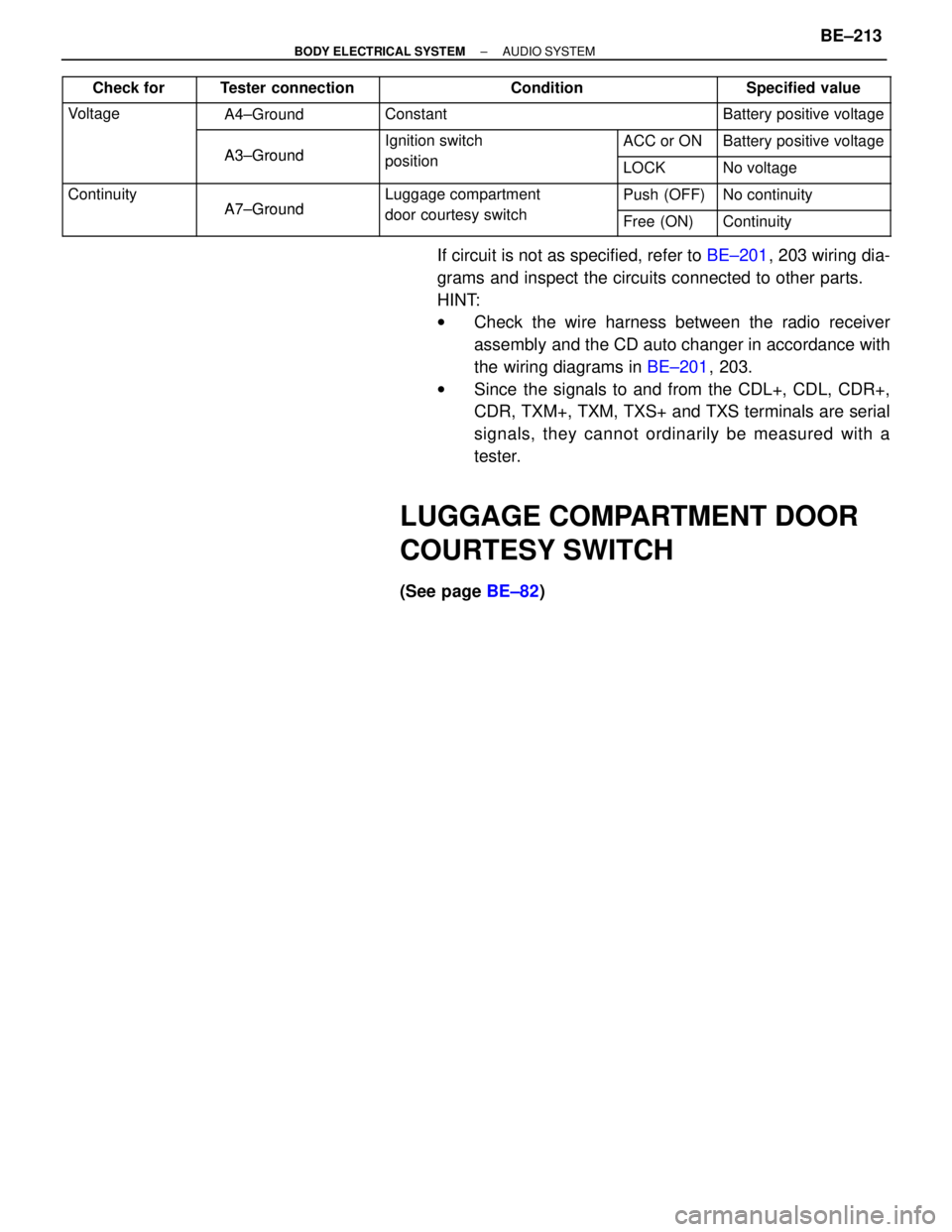
������� �������
Check for�������� ��������Tester connection��������������� ���������������Condition�������� ��������Specified value
������� �������Voltage�������� ��������A4±Ground��������������� ���������������Constant�������� ��������Battery positive voltage
������� ��������������� ��������
A3±Ground
����������� �����������Ignition switch
iti
����� �����ACC or ON�������� ��������Battery positive voltage
������� ��������������� ��������A3±Ground����������� �����������position����� �����LOCK�������� ��������No voltage
������� �������Continuity�������� ��������
A7±Ground
����������� �����������Luggage compartment
d t it h
����� �����Push (OFF)�������� ��������No continuity������� ��������������� ��������A7±Ground����������� �����������door courtesy switch����� �����Free (ON)�������� ��������Continuity
If circuit is not as specified, refer to BE±201, 203 wiring dia-
grams and inspect the circuits connected to other parts.
HINT:
w Check the wire harness between the radio receiver
assembly and the CD auto changer in accordance with
the wiring diagrams in BE±201, 203.
w Since the signals to and from the CDL+, CDL, CDR+,
CDR, TXM+, TXM, TXS+ and TXS terminals are serial
signals, they cannot ordinarily be measured with a
tester.
LUGGAGE COMPARTMENT DOOR
COURTESY SWITCH
(See page BE±82)
±
BODY ELECTRICAL SYSTEM AUDIO SYSTEMBE±213
WhereEverybodyKnowsYourName
Page 689 of 4087
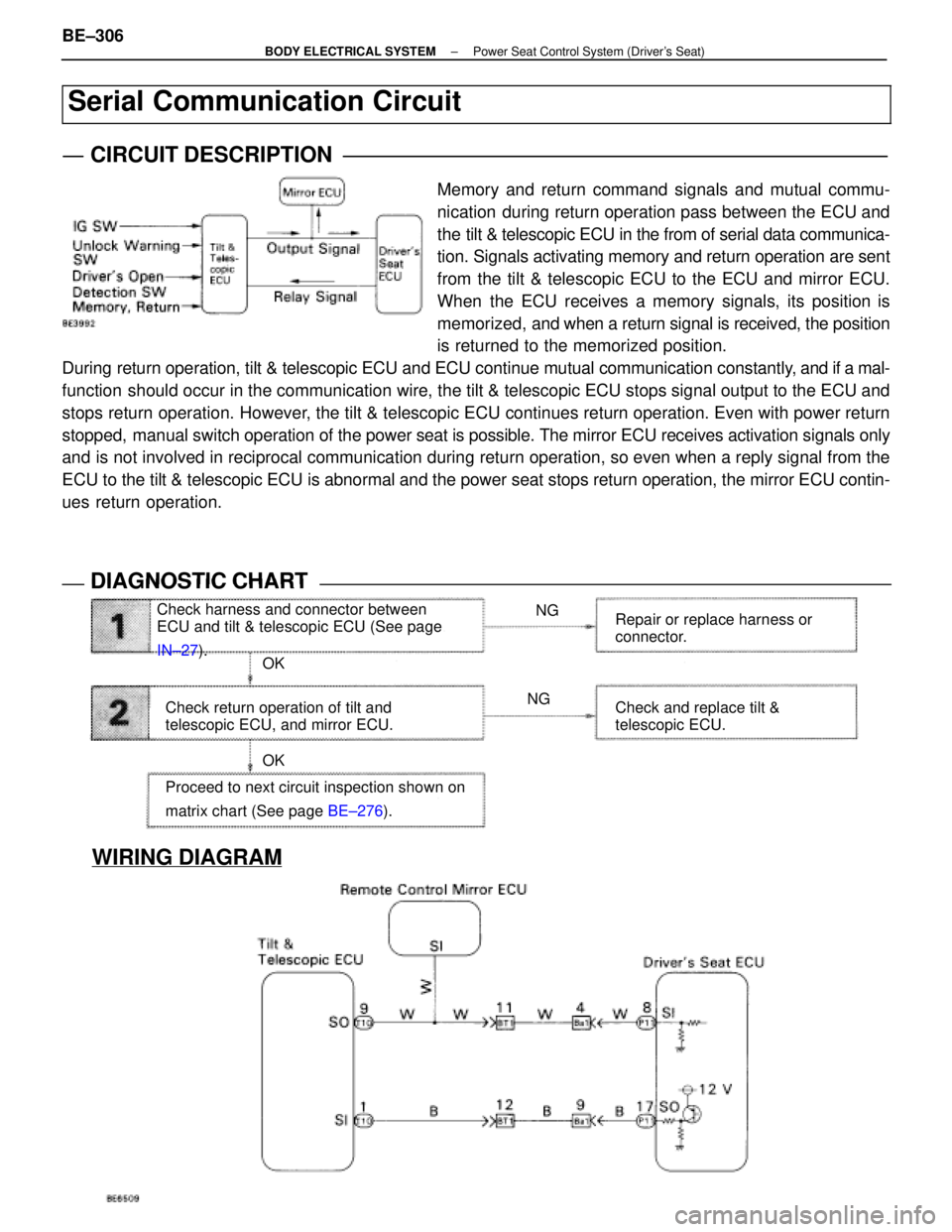
WIRING DIAGRAM
Check harness and connector between
ECU and tilt & telescopic ECU (See page
IN±27). NG
NG
OK
OK
Check return operation of tilt and
telescopic ECU, and mirror ECU. Repair or replace harness or
connector.
Check and replace tilt &
telescopic ECU.
Proceed to next circuit inspection shown on
matrix chart (See page BE±276).
Serial Communication Circuit
CIRCUIT DESCRIPTION
Memory and return command signals and mutual commu-
nication during return operation pass between the ECU and
the tilt & telescopic ECU in the from of serial data communica-
tion. Signals activating memory and return operation are sent
from the tilt & telescopic ECU to the ECU and mirror ECU.
When the ECU receives a memory signals, its position is
memorized, and when a return signal is received, the position
is returned to the memorized position.
During return operation, tilt & telescopic ECU and ECU continue mutual communi\
cation constantly, and if a mal-
function should occur in the communication wire, the tilt & telescopic ECU stops signal output to the ECU and
stops return operation. However, the tilt & telescopic ECU continues return operation. Even with power \
return
stopped, manual switch operation of the power seat is possible. The mirror ECU receives activation signals only
and is not involved in reciprocal communication during return operation, so\
even when a reply signal from the
ECU to the tilt & telescopic ECU is abnormal and the power seat stops retur\
n operation, the mirror ECU contin-
ues return operation.
DIAGNOSTIC CHARTDIAGNOSTIC CHART
BE±306±
BODY ELECTRICAL SYSTEM Power Seat Control System (Driver's Seat)
WhereEverybodyKnowsYourName