Page 2742 of 4087
OKNG
OKNG
YESNO
INSPECTION PROCEDURE
1Check EFI fuse.
C
OK
PRemove EFI fuse from R/B No.2.
Check continuity of EFI fuse.
Continuity
Check for short in all the harness and components con-
nected to EFI fuse (See attached wiring diagram).
2Check voltage between terminal BATT of engine & ECT ECU connector and body ground.
C
OK
PConnect the Check Harness A.
(See page TR±30).
Measure voltage between terminal BATT of engine &
ECT ECU connector and body ground.
Voltage: 10 ± 14 V
Check and repair harness or connector between engine
& ECT ECU and EFI fuse, EFI fuse and battery.
3Are the diagnostic codes still in the memory when the ignition switch is\
turned OFF?
Check and replace engine & ECT ECU.
Proceed to next circuit inspection shown on ma-
trix chart (See page TR±35).
±
ENGINE TROUBLESHOOTING Circuit InspectionTR±131
WhereEverybodyKnowsYourName
Page 2759 of 4087

DEFOGGER SYSTEM
Description
The component parts of this system and their functions are described in the\
following table.
��������� ���������Parts Name������������������\
���������� ������������������\
����������Function
��������� ���������Defogger������������������\
���������� ������������������\
����������When over current flows in the defogger circuit, the Defogger fuse break\
s the circuit to pro-
tect it against damage.
��������� �
��������
���������
Defogger Relay������������������\
���������� �
������������������\
���������
������������������\
����������
This relay is supplied with current from terminal IG1 of ignition switch\
(Ignition switch
ON) and switches large current from the defogger.
��������� �
��������
���������
A/C Control Panel
Assembly
�
Defogger Switch������������������\
���������� �
������������������\
���������
������������������\
����������
The defogger switch is built into the A/C Control Panel Assembly. This switch is
supplied with current from the relay and fuse HTR. Grounds current from \
the defogger
relay, turning the defogger relay ON.
��������� �
��������
�
��������
���������
Defogger
�
Rear Window
� Outer Mirror������������������\
���������� �
������������������\
���������
�
������������������\
���������
������������������\
����������
These defoggers generate heat when current is supplied from the defogger\
relay.
Parts Location
±
BODY ELECTRICAL SYSTEM Lighting SystemBE±51
WhereEverybodyKnowsYourName
Page 2769 of 4087
 Check the specific gravity of each cell.
Standard specific gravity:
1.27±1.29 when fully charged at 20 5C (68 5F)")
ON±VEHICLE INSPECTION
1. INSPECT BATTERY SPECIFIC GRAVITY ANDELECTROLYTE LEVEL
(a) Check the specific gravity of each cell.
Standard specific gravity:
1.27±1.29 when fully charged at 20 5C (68 5F)
If gravity is less than specification, charge the battery.
(b) Check the electrolyte quantity of each cell.
If insufficient, refill with distilled (or purified) water.
HINT: Check the indicator as shown in the illustration.
2. CHECK BATTERY TERMINALS, FUSIBLE LINKS AND FUSES
(a) Check that the battery terminals are not loose orcorroded.
(b) Check the fusible links and fuses for continuity.
H±fuse: ALT 150A AM1 100A
AM2 30A
M±fuse: IG SW 40A
Fuse: IGN 7.5A ENGINE 7.5A
INJ 30A
3. INSPECT DRIVE BELTHINT: A belt tensioner is used, so checking the belt tension
is not necessary.
(a) Visually check the drive belt for excessive wear, frayedcords, etc.
If necessary, replace the drive belt.
HINT:
w Cracks on rib side of a drive belt are considered
acceptable. If the drive belt has chunks missing from the
ribs, it should be replaced.
w The drive belt tension can be released by turning the
belt tensioner counterclockwise. The pulley bolt for the
belt tensioner has a left±hand thread.
±
CHARGING SYSTEM On±Vehicle InspectionCH±5
WhereEverybodyKnowsYourName
Page 2953 of 4087
NGOK
OKNG
INSPECTION PROCEDURE
1Check voltage between terminal IG of ECU connector and body ground.
C
OK
PRemove ECU with connectors still connected.
Measure voltage between terminal EG of ECU connec-
tor and body ground when ignition switch is on and off.
Proceed to next circuit inspection shown on matrix chart
(See page SR±52.)
2Check ECU±IG fuse.
C
OK
PRemove ECU±IG fuse from J/B No. 1.
Check continuity of ECU±IG fuse.
Continuity
Check for short in all the harness and components con-
nected to ECU±IG fuse.
Check and repair harness or connector between
ECU and battery.
±
STEERING STEERING COLUMNSR±93
WhereEverybodyKnowsYourName
Page 3086 of 4087
OKNG
3Check DOME Fuse.
C
OK
PRemove DOME Fuse from R/B No. 2.
Check continuity of DOME Fuse.
Continuity
Check for short in all the harness and components con-
nected to DOME Fuse (See attached wiring diagram).
Check harness and connector between ECU and
battery (See page
IN±33).
SR±64±
STEERING STEERING COLUMN
WhereEverybodyKnowsYourName
Page 3112 of 4087

CENTER AIRBAG SENSOR ASSEMBLY CONNECTOR
RS00V±0B
����� �����No.����������������� �����������������Symbol���������������� ����������������Terminal Name����� �����A����������������� �����������������±���������������� ����������������Electrical Connection Check Mechanism����� �����B����������������� �����������������±���������������� ����������������Electrical Connection Check Mechanism����� �����1����������������� �����������������P±���������������� ����������������Squib ��(Passenger)����� �����2����������������� �����������������P+���������������� ����������������Squib � (Passenger)����� �����3����������������� �����������������D+���������������� ����������������Squib � (Driver)����� �����4����������������� �����������������D±���������������� ����������������Squib � (Driver)����� �����5����������������� �����������������E1���������������� ����������������Ground����� �����6����������������� �����������������E2���������������� ����������������Ground����� �����7����������������� �����������������Tc���������������� ����������������Diagnosis����� �����8����������������� �����������������+SR���������������� ����������������Front Airbag Sensor RH ������ �����9����������������� �����������������±SR���������������� ����������������Front Airbag Sensor RH ������ �����10����������������� �����������������±SL���������������� ����������������Front Airbag Sensor LH ������ �����11����������������� �����������������+SL���������������� ����������������Front Airbag Sensor LH ������ �����12����������������� �����������������LA���������������� ����������������SRS Warning Light����� �����13����������������� �����������������IG2���������������� ����������������Power Source (IGN Fuse)����� �����14����������������� �����������������ACC���������������� ����������������Power Source (CIG Fuse)
RS±8±
SUPPLEMENTAL RESTRAINT SYSTEM DESCRIPTION
WhereEverybodyKnowsYourName
Page 3209 of 4087
OKNG
OKNG
INSPECTION PROCEDURE
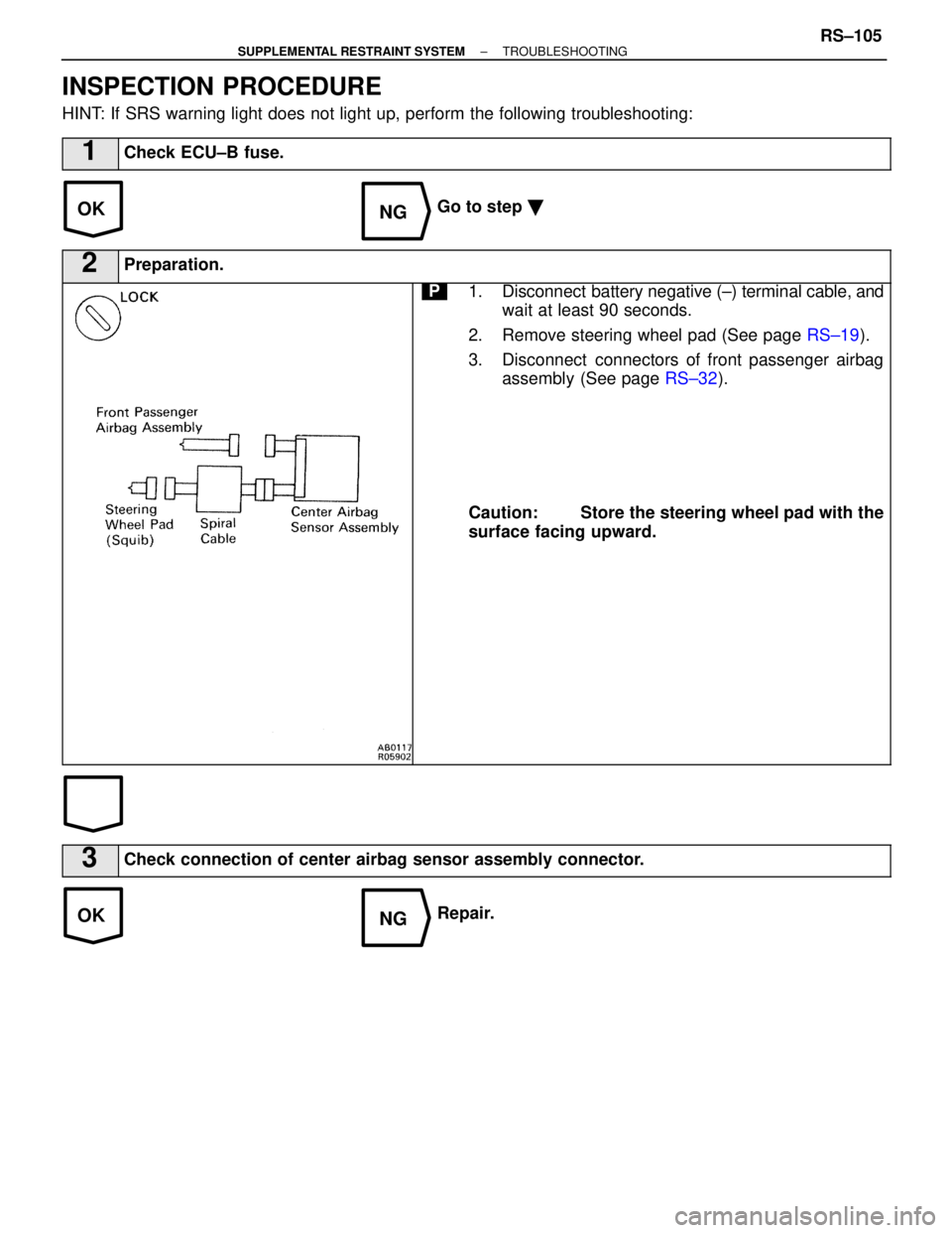
HINT: If SRS warning light does not light up, perform the following troublesh\
ooting:
1Check ECU±B fuse.
Go to step �
2Preparation.
P1. Disconnect battery negative (±) terminal cable, and
wait at least 90 seconds.
2. Remove steering wheel pad (See page RS±19).
3. Disconnect connectors of front passenger airbag assembly (See page RS±32).
Caution: Store the steering wheel pad with the
surface facing upward.
3Check connection of center airbag sensor assembly connector.
Repair.
±
SUPPLEMENTAL RESTRAINT SYSTEM TROUBLESHOOTINGRS±105
WhereEverybodyKnowsYourName
Page 3210 of 4087
 terminal cable to battery.
3. Turn ignition switch ACC or ON.
Measure vo")
OKNG
YESNO
YESNO
4Check SRS warning light circuit.
C
OK
P1. Disconnect center airbag sensor assembly.
2. Connect negative (±) terminal cable to battery.
3. Turn ignition switch ACC or ON.
Measure voltage LA terminal of harness side connector
of center airbag sensor assembly.
Voltage: Battery positive voltage.
Repair SRS warning light circuit.
5Does SRS warning light come on?
C
OK
P1. Disconnect negative (±) terminal cable from bat-tery.
2. Connect center airbag sensor assembly.
3. Connect negative (±) terminal cable to battery.
4. Turn ignition switch ACC or ON.
Check operation of SRS warning light.
SRS warning light comes on.
Check terminal LA of center airbag sensor assembly and
electrical connection check mechanism. If normal, re-
place center airbag sensor assembly.
From the results of the above inspection, the malfunctioning part can now be\
considered normal. To
make sure of this, use the simulation method to check.
6Is new ECU±B fuse burnt out again?
Using simulation method, reproduce malfunction symp-
toms (See page RS±65).
Check harness between ECU±B fuse and SRS warning light, and ECU±B fuse a\
nd center airbag sensor
assembly.
RS±106±
SUPPLEMENTAL RESTRAINT SYSTEM TROUBLESHOOTING
WhereEverybodyKnowsYourName