Page 41 of 4087

R±12 AIR CONDITIONER SYSTEM RETROFIT ± AC001±98 April 3, 1998
Page 4 of 4
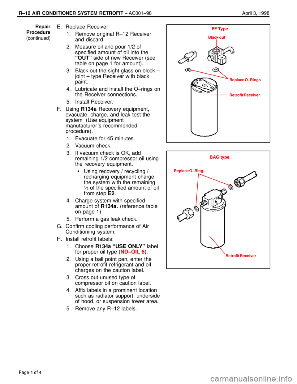
E. Replace Receiver
1. Remove original R±12 Receiverand discard.
2. Measure oil and pour 1/2 of specified amount of oil into the
ªOUTº side of new Receiver (see
table on page 1 for amount).
3. Black out the sight glass on block ± joint ± type Receiver with black
paint.
4. Lubricate and install the O±rings on the Receiver connections.
5. Install Receiver.
F. Using R134a Recovery equipment,
evacuate, charge, and leak test the
system (Use equipment
manufacturer 's recommended
procedure).
1. Evacuate for 45 minutes.
2. Vacuum check.
3. If vacuum check is OK, add remaining 1/2 compressor oil using
the recovery equipment.
� Using recovery / recycling /
recharging equipment charge
the system with the remaining
½ of the specified amount of oil
from step E2.
4. Charge system with specified amount of R134a. (reference table
on page 1).
5. Perform a gas leak check.
G. Confirm cooling performance of Air Conditioning system.
H. Install retrofit labels:
1. Choose R134a ªUSE ONLYº label
for proper oil type ( ND±OIL 8).
2. Using a ball point pen, enter the proper retrofit refrigerant and oil
charges on the caution label.
3. Cross out unused type of compressor oil on caution label.
4. Affix labels in a prominent location such as radiator support, underside
of hood, or suspension tower area.
5. Remove any R±12 labels.Repair
Procedure
(continued)FF Type
Black out
Replace O±Rings
Retrofit Receiver
BAG type
Replace O±Ring
Retrofit Receiver
WhereEverybodyKnowsYourName
Page 482 of 4087

BODY DIMENSIONS
Description
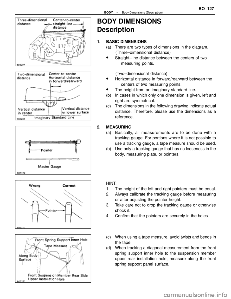
1. BASIC DIMENSIONS(a) There are two types of dimensions in the diagram. (Three±dimensional distance)
wStraight±line distance between the centers of two
measuring points.
(Two±dimensional distance)
wHorizontal distance in forward/rearward between the centers of two measuring points.
wThe height from an imaginary standard line.
(b) In cases in which only one dimension is given, left and right are symmetrical.
(c) The dimensions in the following drawing indicate actual
distance. Therefore, please use the dimensions as a
reference.
2. MEASURING (a) Basically, all measurements are to be done with atracking gauge. For portions where it is not possible to
use a tracking gauge, a tape measure should be used.
(b) Use only a tracking gauge that has no looseness in the body, measuring plate, or pointers.
HINT:
1. The height of the left and right pointers must be equal.
2. Always calibrate the tracking gauge before measuring or after adjusting the pointer height.
3. Take care not to drop the tracking gauge or otherwise shock it.
4. Confirm that the pointers are securely in the holes.
(c) When using a tape measure, avoid twists and bends in
the tape.
(d) When tracking a diagonal measurement from the front
spring support inner hole to the suspension member
upper rear installation hole, measure along the front
spring support panel surface.
±
BODY Body Dimensions (Description)BO±127
WhereEverybodyKnowsYourName
Page 490 of 4087
Suspension Crossmember Drawings
(Three±Dimensional Distance)
(Two±Dimensional Distance)
SymbleNameHole dia.SymbleNameHole dia.
A,aSteering gear box installation hole front12 (0.47)E,eLower arm installation hole ± front25 x 16
(0.98 x 0.63)
B,bUpper arm installation hole front14 (0.55)F, fLower arm installation hole rear25 x 16
(0.98 x 0.63)
C,cSuspension crossmember installation
hole front ± lower15 (0.59)G,gLower arm installation hole rear14 (0.55)
D,dSteering gear box installation
hole ± lower12 (0.47)H,hSuspension crossmember installation
hole rear ± lowerRH 15 x 13
(0.59 x 0.51)
LH 13 x (0.51)
±
BODY Body Dimensions (Suspension Crossmember Drawings)BO±135
WhereEverybodyKnowsYourName
Page 491 of 4087
Suspension Crossmember Drawings (Cont'd)
(Three±Dimensional Distance)(Two±Dimensional Distance)
SymbleNameHole dia.SymbleNameHole dia.
I,iSuspension crossmember installation
hole front ± lower18 (0.71)L,lSuspension crossmember installation
hole rear ± lower18 (0.71)
J,jLower arm installation hole ± front30 x 16
(1.18 x 0.63)M,mSuspension crossmember installation
hole rear ± lower18 (0.71)
K,kLower arm installation hole rear30 x 16
(1.18 x 0.63)'''
BO±136±
BODY Body Dimensions (Suspension Crossmember Drawings)
WhereEverybodyKnowsYourName
Page 492 of 4087
Suspension Crossmember Drawings (Cont'd)
(Three±Dimensional Distance)
(Two±Dimensional Distance)
SymbleNameHole dia.SymbleNameHole dia.
A,aStrut bar installation hole inner14 (0.55)F, fLower arm installation hole front26 x 14
(1.02 x 0.55)
B,bDifferential carrier installation hole12 (0.47) screwG,gRear suspension member standard hole20 (0.78)
C,cRear suspension member standard hole20 (0.78)H,hLower arm installation hole rear26 x 14
(1.02 x 0.55)
D,dLower arm installation hole front26 x 14
(1.02 x 0.55)I,iUpper arm installation hole rear14 (0.55)
E,eUpper arm installation hole front14 (0.55)'''
±
BODY Body Dimensions (Suspension Crossmember Drawings)BO±137
WhereEverybodyKnowsYourName
Page 1231 of 4087

GENERAL INFORMATION
1. BASIC DIMENSIONS
(a) There are two types of dimensions in the diagram.(Three-dimensional distance)
�Straight-line distance between the centers of two
measuring points.
(Two-dimensional distance)
� Horizontal distance in forward/rearward between
the centers of two measuring points.
� The height from an imaginary standard line.
(b) In cases in which only one dimension is given, left and right are symmetrical.
(c) The dimensions in the following drawing indicate actual distance. Therefore, please use the dimen-
sions as a reference.
2. MEASURING
(a) Basically, all measurements are to be done with atracking gauge. For portions where it is not possible
to use a tracking gauge, a tape measure should be
used.
(b) Use only a tracking gauge that has no looseness in the body, measuring plate, or pointers.
HINT:
1. The height of the left and right pointers must be equal.
2. Always calibrate the tracking gauge before measuring or after adjusting the pointer height.
3. Take care not to drop the tracking gauge or otherwise shock it.
4. Confirm that the pointers are securely in the holes.
(c) When using a tape measure, avoid twists and bends in the tape.
(d) When tracking a diagonal measurement from the front spring support inner hole to the suspension
member upper rear installation hole, measure
along the front spring support panel surface.
Center-to-center
straight-line
distance
Three-dimensional
distance
Front Spring Support Inner HoleTape Measure
Along Body
Surface Front Suspension Member Rear Side
Upper Installation Hole Master Gauge
Pointer
Pointer LoosenessBody Looseness
Plate Looseness
Two-dimensional
distance
Center-to-center
Horizontal distance in
forward/rearward
Vertical distance
in lower surface
Vertical distance
in center
Imaginary Standard Line
Wrong Correct
Pointer
BODY DIMENSIONSDI-2
WhereEverybodyKnowsYourName
Page 1233 of 4087
BO6847
mm (in.)
(Three-Dimensional Distance)
Hole dia.
18 (0.71)
18 (0.71)
10 (0.39) screw
12 (0.47) screw
Name
Front floor reinforcement standard hole
Rear floor side member standard hole
Suspension member bracket installation nut rear = outer
Transport hook installation nut front = outer
Symbol
L, l
M, m
P, p
Q, q
Hole dia.
6 (0.24) screw
18 (0.71) 13 (0.51)
18 (0.71)
Name
Radiator duct installation nut
Front side member standard holeFront suspension crossmember installation hole
Front side member standard hole
Symbol
A, a
D, d F, f
I, i
UNDER BODY
BODY DIMENSIONSDI-4
WhereEverybodyKnowsYourName
Page 1234 of 4087
BO6847
mm (in.)
(Three-Dimensional Distance)
Hole dia.
10 (0.39) screw
14 (0.55) screw
10 (0.39) screw
Name
Propeller shaft center support bearing installation nut
Rear suspension member installation nut
Suspension member bracket installation nut rear = outer
Symbol
K, k
N, n
P, p
Hole dia.
9 (0.35)
18 (0.71)
10 (0.39) screw
Name
Front crossmember working hole
Front suspension crossmember installation nut
Engine rear mounting member installation hole
Symbol
B, bH, h J, j
UNDER BODY (Cont'd)
BODY DIMENSIONSDI-5
WhereEverybodyKnowsYourName