Page 2398 of 4087

If there is no pressure, check the following parts:w Fuses
w EFI main relay
w Fuel pump ECU
w Fuel pump
w Engine & ECT ECU
w Wiring connections
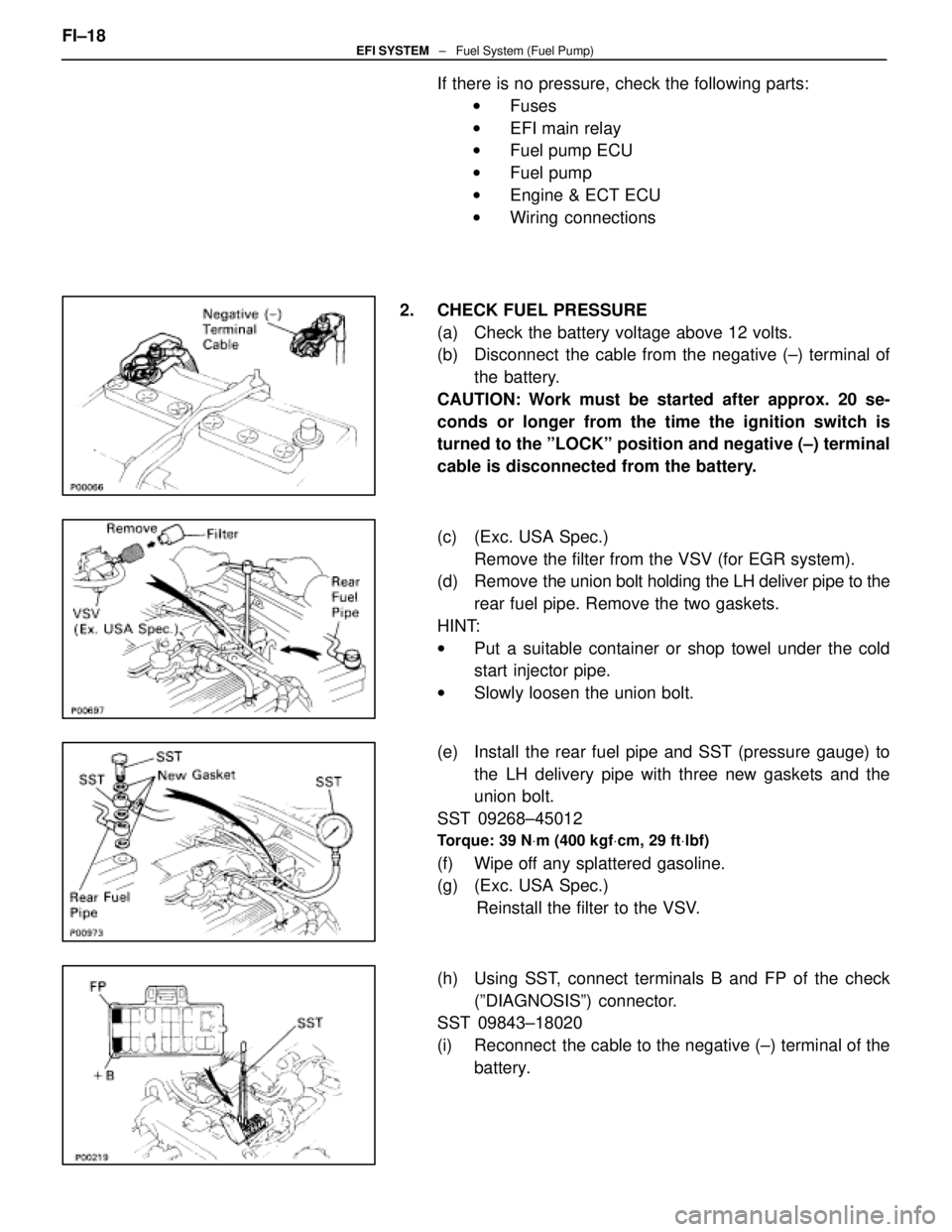
2. CHECK FUEL PRESSURE (a) Check the battery voltage above 12 volts.
(b) Disconnect the cable from the negative (±) terminal ofthe battery.
CAUTION: Work must be started after approx. 20 se-
conds or longer from the time the ignition switch is
turned to the ºLOCKº position and negative (±) terminal
cable is disconnected from the battery.
(c) (Exc. USA Spec.) Remove the filter from the VSV (for EGR system).
(d) Remove the union bolt holding the LH deliver pipe to the
rear fuel pipe. Remove the two gaskets.
HINT:
w Put a suitable container or shop towel under the cold
start injector pipe.
w Slowly loosen the union bolt.
(e) Install the rear fuel pipe and SST (pressure gauge) to the LH delivery pipe with three new gaskets and the
union bolt.
SST 09268±45012
Torque: 39 N Vm (400 kgf Vcm, 29 ft Vlbf)
(f) Wipe off any splattered gasoline.
(g) (Exc. USA Spec.)
Reinstall the filter to the VSV.
(h) Using SST, connect terminals B and FP of the check (ºDIAGNOSISº) connector.
SST 09843±18020
(i) Reconnect the cable to the negative (±) terminal of the
battery.
FI±18
EFI SYSTEM
± Fuel System (Fuel Pump)
WhereEverybodyKnowsYourName
Page 2621 of 4087

DIAGNOSIS SYSTEM
DESCRIPTION
The ECU contains a built±in self±diagnosis system by which
troubles with the engine signal network are detected and a
ºCHECKº engine warning light on the instrument panel lights up.
By analyzing various signals as shown in the later table (See page
TR±14) the Electronic Control Unit (ECU) detects system malfunc-
tions relating to the sensors or actuators.
In the normal mode, the self±diagnosis system monitors 22 (USA
specification vehicles with TRAC control) or 21 (USA (except for
California) and Canadian specification vehicles with TRAC con-
trol) items, indicated by code No. as shown in TR±14. A ºCHECKº
engine warning light informs the driver that a malfunction has been
detected. The light goes off automatically when the malfunction
has been repaired. But the diagnostic code(s) remains stored in
the ECU memory (except for code Nos. 16 and 53). The ECU
stores the code(s) until it is cleared by removing the EFI fuse with
the ignition switch off.
The diagnostic code can be read by the number of blinks of the
ºCHECKº engine warning light when TE1 and E1 terminals on the
TDCL or check connector are connected. When 2 or more codes
are indicated, the lowest number (code) will appear first.
In the test mode, 15 (USA specification vehicles with TRAC con-
trol) or 14 (USA (except for California) and Canadian specification
vehicles with TRAC control) items, indicated by code No. as
shown in TR±14 are monitored. If a malfunction is detected in any
one of the systems indicated by code Nos. 13, 21, 22, 24, 25, 26,
27, 28, 29, 35, 41, 42, 47, 71 and 78 (USA specification vehicles)
or 13, 21, 22, 24, 25, 26, 27, 28, 29, 35, 41, 42, 47 and 78 (USA
(except for California) and Canadian specification vehicles) the
ECU lights the ºCHECKº engine warning light to warn the techni-
cian that malfunction has been detected. In this case, TE2 and E1
terminals on the TDCL should be connected as shown later. (See
page TR±12 ).
In the test mode, even if the malfunction is corrected, the malfunc-
tion code is stored in the ECU memory even when the ignition
switch is off (except code Nos. 43 and 51). This also applies in the
normal mode. The diagnostic mode (normal or test) and the output
of the ºCHECKº engine warning light can be selected by connect-
ing the TE1, TE2 and E1 terminals on the check connector or
TDCL, as shown later.
A test mode function has been added to the functions of the self±
diagnosis system of the normal mode for the purpose of detecting
malfunctions such as poor contact, which are difficult to detect in
the normal mode. This function fills up the selfdiagnosis system.
The test mode can be implemented by the technician following the
appropriate procedures of check terminal connection and opera-
tion described later. (See page TR±12)
TR±10
±
ENGINE TROUBLESHOOTING Diagnosis System
WhereEverybodyKnowsYourName
Page 2624 of 4087
DIAGNOSTIC CODE CLEARANCE
1. After repair of the trouble areas, the diagnostic code retainedin the ECU memory must be cleared out by removing the EFI
fuse (30A) from R/B No. 2 for 10 seconds or more, with the
ignition switch OFF.
HINT:
wCancellation can also be done by removing the battery
negative (±) terminal, but in this case, other memory
systems (clock, etc.) will also be cancelled out.
w If it is necessary to work on engine components
requiring removal of the battery terminal, a check must
first be made to see if a diagnostic code has been
recorded.
2. After cancellation, road test the vehicle to check that a normal
code is now read on the ºCHECKº engine warning light.
If the same diagnostic code appears, it indicates that the
trouble area has not been repaired thoroughly.
±
ENGINE TROUBLESHOOTING Diagnosis SystemTR±13
WhereEverybodyKnowsYourName
Page 2736 of 4087
DIAGNOSTIC CHART
DIAGNOSTIC
CHART
Check for short in all the harness and
components connected to IGN fuse.
Check voltage of terminal M±REL.
Check for open in harness and connector
between battery and ECU.
Check and replace ECU.
Replace ignition switch.
Repair or replace harness or
connector.
Repair or replace harness or
connector.
Check for open and short in harness and
connector between terminal M REL and body
ground.
Replace EFT main relay.
Check voltage of terminal IGSW.
Check IGN fuse.
Check continuity between terminals E1 and
body ground.
Check voltage of ECU power source.
Proceed to next circuit inspection
shown on matrix chart (See page
TR±35
).
Check ignition switch.
Check EFT fuse.
Check EFT main relay.
Check and repair or harness or connector
between EFI fuse and battery.
Check for short in all the harness and
components connected to EFI fuse.
±
ENGINE TROUBLESHOOTING Circuit InspectionTR±125
WhereEverybodyKnowsYourName
Page 2738 of 4087
OKNG
OKNG
4Check IGN Fuse.
C
OK
PRemove IGN fuse from J/B No.1.
Check continuity of IGN fuse.
Continuity.
Check for short in all the harness and components con-
nected to IGN fuse (See attached wiring diagram).
5Check ignition switch.
C
OK
PRemove under cover and finish panel.
Check continuity between terminals.
continuity
Replace ignition switch.
Check and repair harness and connector between
battery and ignition switch, ignition switch and en-
gine & ECT ECU.
±
ENGINE TROUBLESHOOTING Circuit InspectionTR±127
WhereEverybodyKnowsYourName
Page 2739 of 4087
OKNG
OKNG
6Check voltage between terminal M±REL of engine & ECT ECU connector and bod\
y ground.
C
OK
PTurn ignition switch on.
Measure voltage between terminal M±REL of engine &
ECT ECU connection and body ground.
Voltage: 10 ± 14 V
Check and replace engine & ECT ECU.
7Check EFI
C
OK
PRemove EFI fuse R/B No.2.
Check continuity of EFI fuse.
Continuity
Rep
TR±128
±
ENGINE TROUBLESHOOTING Circuit Inspection
WhereEverybodyKnowsYourName
Page 2740 of 4087
OKNG
OKNG
8Check EFI main relay.
C
OK
P
C
OK
Remove EFI main relay.
Check continuity between terminals of EFI main relay
shown below.
(2) Apply battery voltage between terminals 1 and 3.
(2) Check continuity between terminals 2 and 4.
Replace EFI main relay.
9Check for open and short in harness and connector between terminal M±REL o\
f engine & ECT
ECU and body ground (See page IN±27).
Repair or replace harness or connector.
Check and repair harness or connector between
EFI fuse and battery.
±
ENGINE TROUBLESHOOTING Circuit InspectionTR±129
WhereEverybodyKnowsYourName
Page 2741 of 4087
Back Up Power Source Circuit
CIRCUIT DESCRIPTION
Battery voltage is supplied to terminal BATT of the ECU even when the ignition switch is off for use by
the diagnostic code memory and air±fuel ratio adaptive control value mem\
ory, etc.
DIAGNOSTIC CHARTDIAGNOSTIC CHART
Check for short in all the harness and
components connected to EFI fuse.Check EFI fuse.
Check of terminal BATT.
Proceed to next circuit inspection shown on
matrix chart (See page TR±35).
Check operation for the back up.Check and replace ECU.
Check and repair harness or connector
between battery, EFI fuse and ECU.
WIRING DIAGRAM
TR±130±
ENGINE TROUBLESHOOTING Circuit Inspection
WhereEverybodyKnowsYourName