Page 115 of 4087
������������������\
������������������\
�
������������������\
�����������������
������������������\
������������������\
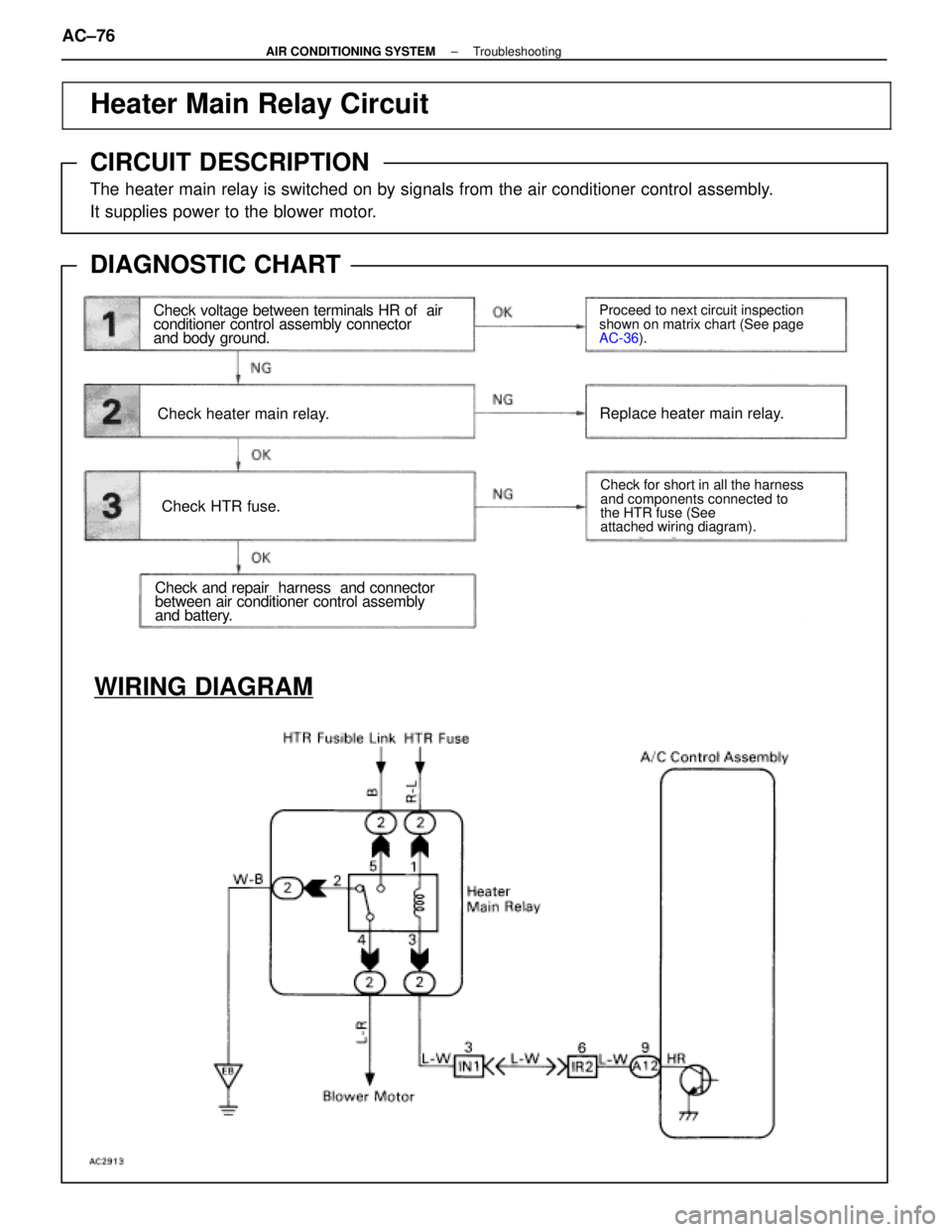
Heater Main Relay Circuit
CIRCUIT DESCRIPTION
The heater main relay is switched on by signals from the air conditioner co\
ntrol assembly.
It supplies power to the blower motor.
DIAGNOSTIC CHART
Check voltage between terminals HR of air
conditioner control assembly connector
and body ground.
Check heater main relay.
Check HTR fuse.
Check and repair harness and connector
between air conditioner control assembly
and battery.
Proceed to next circuit inspection
shown on matrix chart (See page
AC-36
).
Check for short in all the harness
and components connected to
the HTR fuse (See
attached wiring diagram).
Replace heater main relay.
WIRING DIAGRAM
AC±76±
AIR CONDITIONING SYSTEM Troubleshooting
WhereEverybodyKnowsYourName
Page 116 of 4087
 Remove console upper panel.(See page BO-111 ).
(2) Remove A/C control assembly with connec±")
Check voltage between terminals HR of air conditioner control assem-
bly connector and body ground.
(1) Remove console upper panel.(See page BO-111 ).
(2) Remove A/C control assembly with connec±
tors still connected.
Proceed to next circuit inspection shown on ma-
trix chart (See page AC-36).
Check heater main relay.
Check continuity between each pair of terminals of
heater main relay shown below.
Measure voltage between terminals HR of air condi-
tioner control assembly and body ground when
ignition switch is on and off.
(1) Apply battery voltage between terminals 1
and 3
(2) Check continuity between each pair of ter±minal shown below.
Replace heater main relay.
Remove HTR fuse from J/B No. 1.
Check continuity of HTR fuse
Continuity
Check for short in all the harness and
components connected to the HTR fuse
See attached wiring diagram).
Check and repair harness and connector between air conditioner control \
assembly and battery.
INSPECTION PROCEDURE
±
AIR CONDITIONING SYSTEM TroubleshootingAC±77
WhereEverybodyKnowsYourName
Page 191 of 4087

OKNG
1
2
3
4
5
6
6
OK
OK
YES
YES NG
NG NO
NO
Check connection of center airbag sensor
assembly connector.
Preparation.
Check airbag warning light circuit.
Does airbag warning light come on?
Is new ECU ±B fuse burnt out again? GO to step
Repair.
Repair airbag warning light circuit
(See page BE±150).
Check terminal LA of center
airbag sensor assembly and
electrical connection check
mechanism. If normal, replace
center airbag sensor assembly.
Using simulation method,
reproduce malfunction symptoms
(See page IN±20).
Check harness between ECU ±B fuse and
airbag warning light, and ECU±B fuse and
center airbag sensor assembly. From the results of the above inspection,
the malfunctioning part can now be
considered normal. To make sure of this,
use the simulation method to check.
Check ECU ±B fuse.
DIAGNOSTIC CHART
Troubleshooting for this system is different for when the airbag warning light does not light up and for
when diagnostic code 22 is output. Confirm the problem symptoms first before\
selecting the appropriate
troubleshooting procedure.
HINT: If airbag warning light does not light up, perform the following troub\
leshooting:
±
SRS AIRBAG TroubleshootingAB±75
WhereEverybodyKnowsYourName
Page 193 of 4087
Check ECU±B fuse.
NG
OK
1
6Go to step
(1) Disconnect battery negative (±) terminal cable, and wait at least 20 seconds.
(2) Remove steering wheel pad (See page AB±14).
When storing steering wheel pad, keep upper
surface of pad facing upward.
NG
OKRepair.
Check connection of center airbag sensor assembly connector.2
3Preparation.
INSPECTION PROCEDURE
HINT: If airbag warning light does not light up, perform the following troubl\
eshooting:
±
SRS AIRBAG TroubleshootingAB±77
WhereEverybodyKnowsYourName
Page 194 of 4087
 Disconnect negative (±) terminal cab")
4
5
6
Check terminal LA of center airbag sensor assem-
bly and electrical connection check mechanism.
If normal, replace center airbag sensor assembly.
NG
OK
(1) Disconnect negative (±) terminal cable from battery.
(2) Connect center airbag sensor assembly.
(3) Connect negative (±) terminal cable to battery.
(4) Turn ignition switch ACC or ON. Voltage: 10±14 V
Check operation of airbag warning light.
(1) Disconnect center airbag sensor assembly.
(2) Connect negative (±) terminal cable to battery.
(3) Turn ignition switch ACC or ON.
Measure voltage LA terminal of harness side
connector of center airbag sensor assembly.
Repair airbag warning light circuit
(see page BE±150).
NG
Using simulation method, reproduce
malfunction symptoms (See page In±20).NG
OK
Check airbag warning light circuit.
Does airbag warning light come on?
Is new ECU±B fuse burnt out again?
From the results of the above inspection, the malfunctioning part can now be considered norm\
al. To
make sure of this, use the simulation method to check.
Check harness between ECU±B fuse and airbag warning light, and ECU±B fus\
e and center airbag sensor
assembly.
AB±78±
SRS AIRBAG Troubleshooting
WhereEverybodyKnowsYourName
Page 198 of 4087

OK
Check operation of airbag warning light.
NG1
WIRING DIAGRAM
2Is diagnostic code 41 output again? System is normal.
Check harness between ECU±B
fuse and center airbag sensor as-
sembly. If normal, replace center
airbag sensor assembly.
Perform troubleshooting according to
malfunction code output. NO
YES
Diag. Code 41Malfunction Stored in Memory
CIRCUIT DESCRIPTION
If a malfunction occurs in the airbag system, malfunction codes 11 to 31 may be output, and when the
battery is disconnected after the malfunction is repaired, malfunction codes 11 to 31 will be cleared,
but code 41 will be output instead.
So long as the cancellation operation for a malfunction stored in memory (\
See page
AB±32) is not per-
formed, code 41 is stored in the center airbag sensor assembly and the airbag w\
arning light remains
lit up.
Code No.Diagnosis
41 � Malfunction recorded in memory.41 � Center airbag sensor assembly malfunction.
DIAGNOSTIC CHART
AB±82±
SRS AIRBAG Troubleshooting
WhereEverybodyKnowsYourName
Page 199 of 4087
Clear malfunction code 41 stored in memory
(See page AB±32).
Check operation of airbag warning light.
NG
OK
1
Airbag warning light turns off.
(1) Turn ignition switch LOCK, and wait at least
2 seconds.
(2) Turn ignition switch ACC or ON, and wait at least 20 seconds.
(3) Check operation of airbag warning light.
System is normal.
2Is diagnostic code 41 output again?
(1) Turn ignition switch ACC or ON, and wait at least 20 seconds.
(2) Using SST, connect terminals Tc and E
1 of TDCL.
SST 09843±18020
(3) Check diagnostic code.
Check harness between ECU±B fuse and center
airbag sensor assembly. If normal, replace
center airbag sensor assembly.
Perform troubleshooting according to malfunction code output.
NG
OK
INSPECTION PROCEDURE
±
SRS AIRBAG TroubleshootingAB±83
WhereEverybodyKnowsYourName
Page 246 of 4087

Remove the battery negative (±) terminal or ECU±B fuse for
10 seconds or more with the ignition switch OFF.
NOTICE: When")
CLEARING OF DIAGNOSTIC CODE
1. CLEARING OF MALFUNCTION CODE(EXCEPT CODE 41)
Remove the battery negative (±) terminal or ECU±B fuse for
10 seconds or more with the ignition switch OFF.
NOTICE: When connecting the battery after cancelling
the malfunction code, always do it with the ignition
switch in LOCK position. If the battery is connected with
the ignition switch in ACC or ON position, there are cases
when the diagnosis system does not operate normally.
HINT:
wCode 41 cannot be cleared by this method.
wThe lower the temperature, the longer the battery
negative (±) terminal must be left off.
wOther memory systems (clock, audio system) will also
be cancelled out (See page AB±2).
2. CLEARING OF MALFUNCTION CODE 41 STORED IN MEMORY
(a) Connect service wires to terminals Tc and AB of theTDCL.
(b) Turn the ignition switch ACC or ON and wait approx. 6 seconds.
(c) S ta rtin g with th e Tc te rmin a l, ap p ly bo d y gr ound
alternately to terminal Tc and terminal AB twice each in
cycles of 1.0 ± 0.5 seconds. Finally, keep applying body
ground to terminal Tc.
HINT: When alternating between body ground of terminals Tc
and AB release one from body ground while applying it to the
other terminal. The time interval in between must be within
the following conditions. If it is out of the conditions, code 41
will not be cleared.
(d) After several seconds, when the airbag warning light
starts to blink in a 64 msec. cycle, cancellation is
completed.
HINT: This method clears not only code No. 41, but also other
malfunction codes all at once.
Except when instructed by the troubleshooting procedure,
use this method only when the repair procedure is completed
(See page AB±25).
AB±32
SRS AIRBAG
± Troubleshooting
WhereEverybodyKnowsYourName
 Disconnect battery negative (±) terminal cable, and wait at least 20 seconds.
(2) Remove steering wheel pad (See page AB±14).
When storing steering wheel")
.
Check operation of airbag warning light.
NG
OK
1
Airbag warning light turns off.
(1) Turn ignition switch LOCK, and wait at least
2 seco")