Page 2128 of 4087
(d) Lightly screw the oil filter into place, and tighten it untilthe gasket contacts the seat.
(e) Using SST, tighten it an additional 3/4 turn.
SST 09228±07500
3. FILL WITH ENGINE OIL (a) Clean and install the oil drain plug with a new gasket.
Torque: 45 N Vm (450 kgf Vcm, 33 ft Vlbf)
(b) Fill with fresh engine oil.
Oil grade: See page LU±5
Capacity:
Drain and refill w/ Oil filter change
4.8 liters (5.1 US qts, 4.2 lmp. qts)
w/o Oil filter change
4.5 liters (4.8 US qts, 4.0 lmp. qts)
Dry fill 5.2 liters (5.5 US qts, 4.6 lmp. qts)
(c) Reinstall the oil filler cap.
4. START ENGINE AND CHECK FOR LEAKS
5. RECHECK ENGINE OIL LEVEL (See page LU±5)
LU±8
±
LUBRICATION SYSTEM Replacement of Engine Oil and Oil Filter
WhereEverybodyKnowsYourName
Page 2134 of 4087

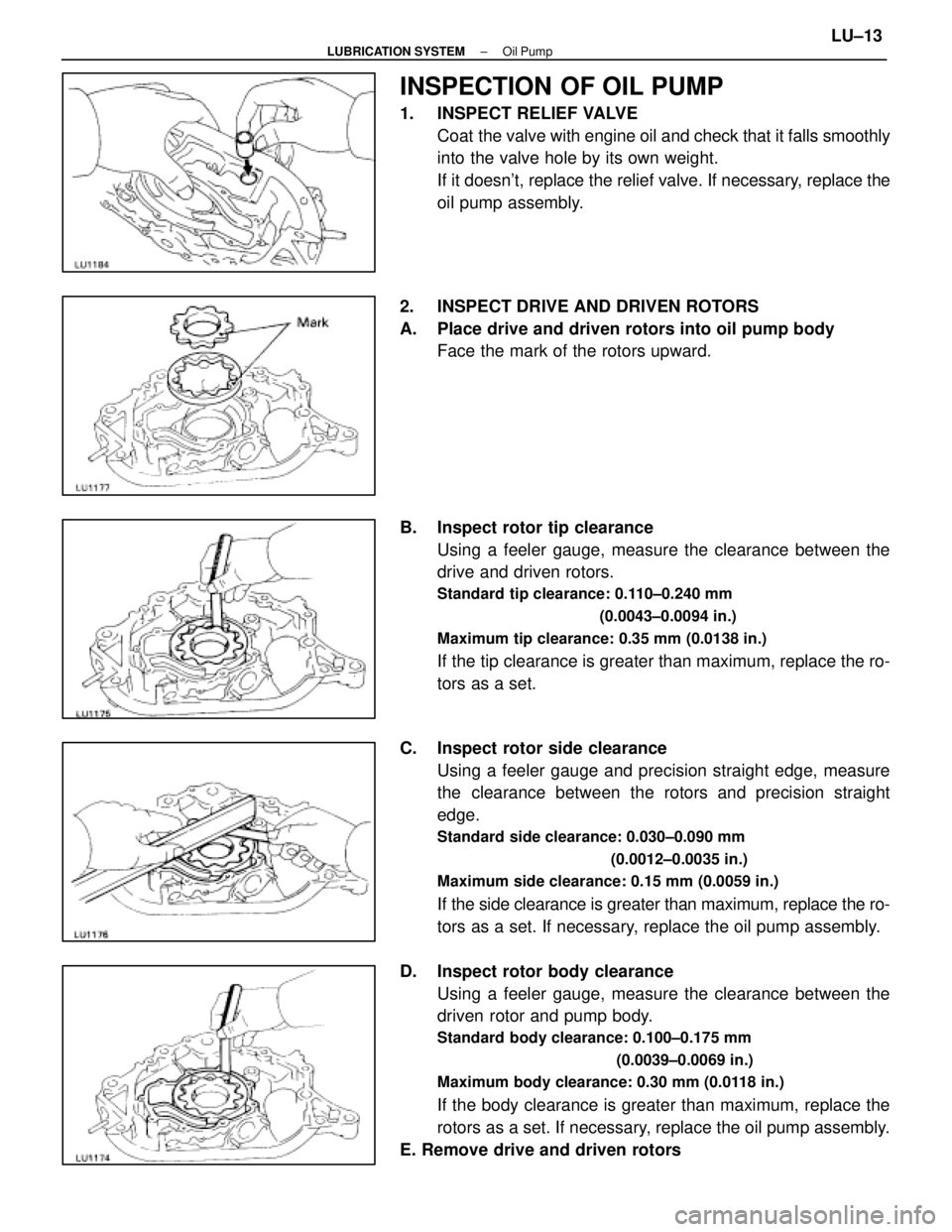
INSPECTION OF OIL PUMP
1. INSPECT RELIEF VALVECoat the valve with engine oil and check that it falls smoothly
into the valve hole by its own weight.
If it doesn't, replace the relief valve. If necessary, replace the
oil pump assembly.
2. INSPECT DRIVE AND DRIVEN ROTORS
A. Place drive and driven rotors into oil pump body Face the mark of the rotors upward.
B. Inspect rotor tip clearance Using a feeler gauge, measure the clearance between the
drive and driven rotors.
Standard tip clearance: 0.110±0.240 mm
(0.0043±0.0094 in.)
Maximum tip clearance: 0.35 mm (0.0138 in.)
If the tip clearance is greater than maximum, replace the ro-
tors as a set.
C. Inspect rotor side clearance Using a feeler gauge and precision straight edge, measure
the clearance between the rotors and precision straight
edge.
Standard side clearance: 0.030±0.090 mm
(0.0012±0.0035 in.)
Maximum side clearance: 0.15 mm (0.0059 in.)
If the side clearance is greater than maximum, replace the ro-
tors as a set. If necessary, replace the oil pump assembly.
D. Inspect rotor body clearance Using a feeler gauge, measure the clearance between the
driven rotor and pump body.
Standard body clearance: 0.100±0.175 mm
(0.0039±0.0069 in.)
Maximum body clearance: 0.30 mm (0.0118 in.)
If the body clearance is greater than maximum, replace the
rotors as a set. If necessary, replace the oil pump assembly.
E. Remove drive and driven rotors
±
LUBRICATION SYSTEM Oil PumpLU±13
WhereEverybodyKnowsYourName
Page 2145 of 4087

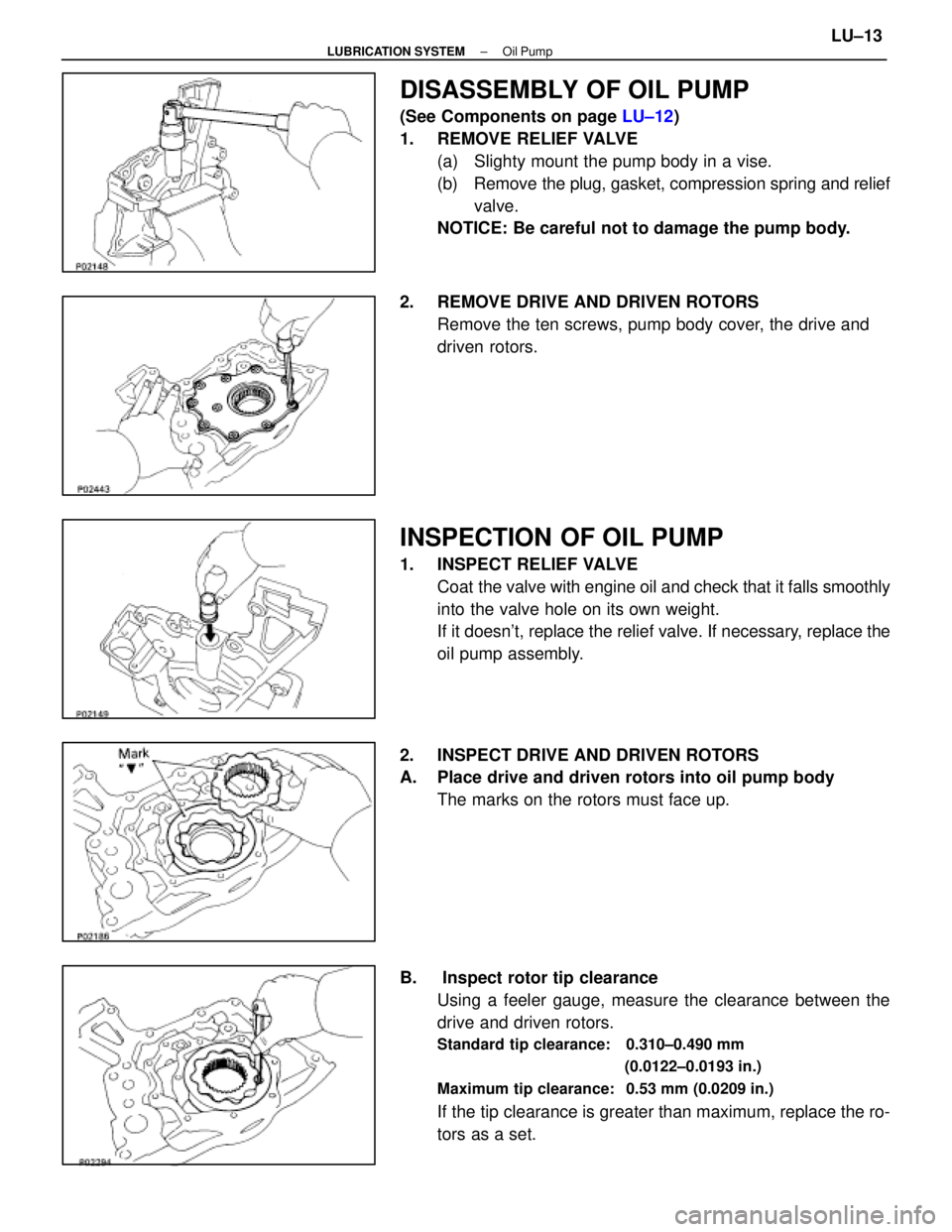
DISASSEMBLY OF OIL PUMP
(See Components on page LU±12)
1. REMOVE RELIEF VALVE (a) Slighty mount the pump body in a vise.
(b) Remove the plug, gasket, compression spring and reliefvalve.
NOTICE: Be careful not to damage the pump body.
2. REMOVE DRIVE AND DRIVEN ROTORS Remove the ten screws, pump body cover, the drive and
driven rotors.
INSPECTION OF OIL PUMP
1. INSPECT RELIEF VALVECoat the valve with engine oil and check that it falls smoothly
into the valve hole on its own weight.
If it doesn't, replace the relief valve. If necessary, replace the
oil pump assembly.
2. INSPECT DRIVE AND DRIVEN ROTORS
A. Place drive and driven rotors into oil pump body The marks on the rotors must face up.
B. Inspect rotor tip clearance Using a feeler gauge, measure the clearance between the
drive and driven rotors.
Standard tip clearance: 0.310±0.490 mm
(0.0122±0.0193 in.)
Maximum tip clearance: 0.53 mm (0.0209 in.)
If the tip clearance is greater than maximum, replace the ro-
tors as a set.
±
LUBRICATION SYSTEM Oil PumpLU±13
WhereEverybodyKnowsYourName
Page 2154 of 4087
V04535
(4) Also applicable to drum lining for parking brake. For other usage condit\
ions, refer to SCHEDULE B.
(5) Check for leakage.
(6) Check for oil leaks from steering gear housing.
(7) Applicable only when operating mainly on rough, muddy roads. The applicable parts \
are listed below. Forother usage conditions, refer to SCHEDULE B.
�Front and rear suspension member to cross body.
� Bolts for seat installation.
±
MAINTENANCE (1UZ ± FE)MA±3
WhereEverybodyKnowsYourName
Page 2155 of 4087
MA033±0C
SCHEDULE B
CONDITIONS:
Conditions others than those listed for SCHEDULE A.Maintenance operation: A = Check and adjust if necessary. R = Replace, change or lubricate.
I = Inspect and correct or replace if necessary.
V04409
� mark indicates maintenance which is part of the warranty conditions for\
the Emission Control Systems.
The warranty period is in accordance with the owner's guide or the warranty booklet.
( � : California and New York specification vehicles only)
(1) Includes inspection of fuel tank band and vaper vent system.
(2) Also applicable to drum lining for parking brake.
(3) Check for leakage.
(4) Check for oil leaks from steering gear housing.
(5) The applicable parts are listed below. �Front and rear suspension member to cross body.
� Bolts for seat installation.
MA±4
±
MAINTENANCE (1UZ ± FE)
WhereEverybodyKnowsYourName
Page 2158 of 4087
wAfter installing a drive belt, check that it fits properly in
the ribbed grooves.
w Check by hand to confirm that the belt has not slipped
out of the groove on the bottom of the pulley.
3. INSPECT AIR FILTER
(a) Open the air cleaner cap.
(b) Remove the air filter.
(c) Visually check that the air filter is not excessively damaged or oily.
If necessary, replace the air filter.
(d) Clean the air filter with compressed air. First blow from the inside thoroughly, then blow off from the
outside of the air filter.
(e) Reinstall the air filter and air cleaner cap.
4. REPLACE AIR FILTER Replace the air filter with a new one.
±
MAINTENANCE (1UZ ± FE)MA±7
WhereEverybodyKnowsYourName
Page 2160 of 4087

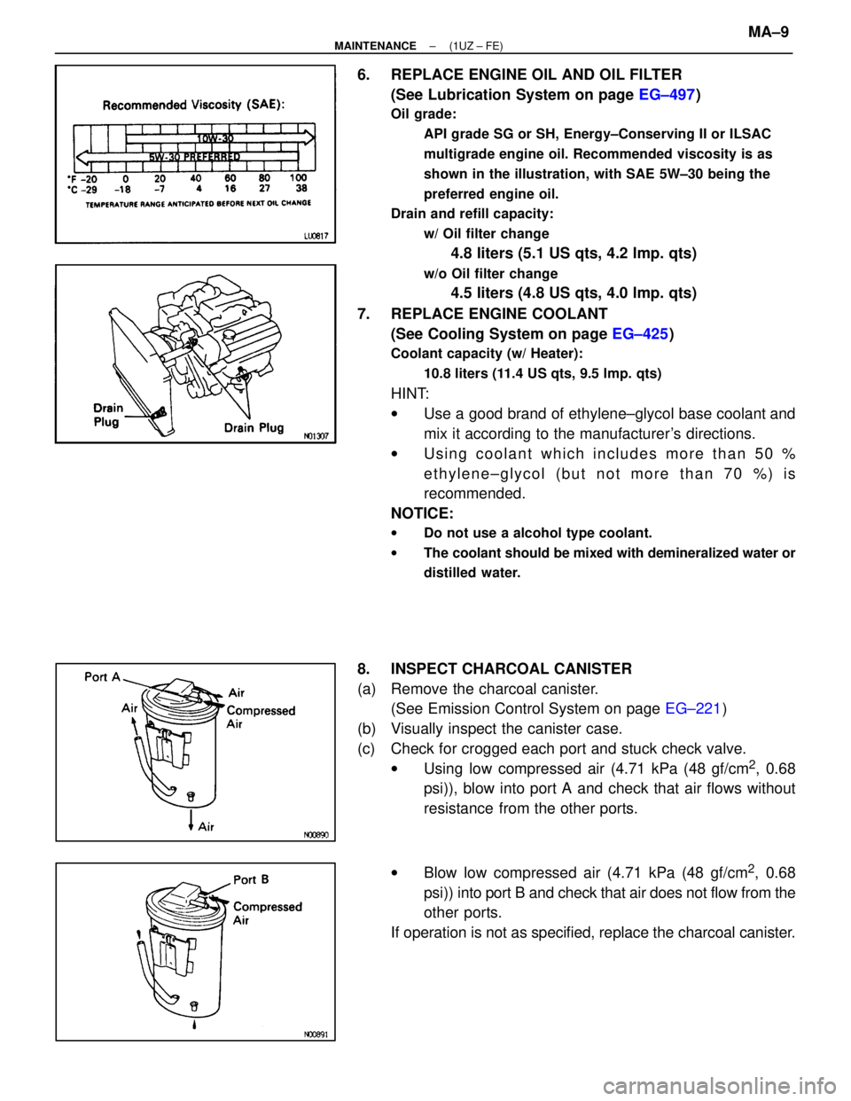
6. REPLACE ENGINE OIL AND OIL FILTER(See Lubrication System on page EG±497)
Oil grade:
API grade SG or SH, Energy±Conserving II or ILSAC
multigrade engine oil. Recommended viscosity is as
shown in the illustration, with SAE 5W±30 being the
preferred engine oil.
Drain and refill capacity:
w/ Oil filter change
4.8 liters (5.1 US qts, 4.2 lmp. qts)
w/o Oil filter change
4.5 liters (4.8 US qts, 4.0 lmp. qts)
7. REPLACE ENGINE COOLANT (See Cooling System on page EG±425)
Coolant capacity (w/ Heater):
10.8 liters (11.4 US qts, 9.5 lmp. qts)
HINT:
wUse a good brand of ethylene±glycol base coolant and
mix it according to the manufacturer's directions.
w Using coolant which includes more than 50 %
ethylene±glycol (but not more than 70 %) is
recommended.
NOTICE:
w Do not use a alcohol type coolant.
w The coolant should be mixed with demineralized water or
distilled water.
8. INSPECT CHARCOAL CANISTER
(a) Remove the charcoal canister.
(See Emission Control System on page EG±221)
(b) Visually inspect the canister case.
(c) Check for crogged each port and stuck check valve. wUsing low compressed air (4.71 kPa (48 gf/cm
2, 0.68
psi)), blow into port A and check that air flows without
resistance from the other ports.
w Blow low compressed air (4.71 kPa (48 gf/cm
2, 0.68
psi)) into port B and check that air does not flow from the
other ports.
If operation is not as specified, replace the charcoal canister.
±
MAINTENANCE (1UZ ± FE)MA±9
WhereEverybodyKnowsYourName
Page 2165 of 4087

18. INSPECT SRS AIRBAGDriver Airbag:
Visually inspect the steering wheel pad (airbag and inflater).
wUse the diagnosis check to check if there are
abnormalities.
w Check that there are no cuts, cracks or noticeable color
changes on the surface of the steering wheel pad or in
the center groove of the pad.
w Remove the steering wheel pad from the vehicle and
check the wiring and steering wheel for damage and
corrosion due to rusting, etc.
If necessary, replace the steering wheel pad.
Front Passenger Airbag:
Visually inspect the front passenger airbag assembly (airbag
and inflater).
w Use the diagnosis check to check if there are
abnormalities.
w Check that there are no cuts, cracks or noticeable color
changes in the front passenger airbag door.
w Remove the front passenger airbag assembly from the
vehicle and check the wiring and front passenger airbag
door for damage and corrosion due to rusting, etc.
If necessary, replace the front passenger airbag assembly.
CAUTION:
w For removal and replacement of the steering wheel pad
or front passenger airbag assembly, see page RS±28 and
be sure to perform the operation in the correct order.
w Before disposing of the steering wheel pad or front
passenger airbag assembly must first be deployed by
using SST and wiring harness connector (See page
RS±28 ).
19. INSPECT STEERING GEAR HOUSING OIL
Check the steering gear housing for oil leakage.
MA±14
±
MAINTENANCE (1UZ ± FE)
WhereEverybodyKnowsYourName