Page 2350 of 4087
(b) Align the oil holes of the connecting rod and a newbushing.
(c) Using SST and a press, press in the bushing.
SST 09222±30010
(d) Using a pin hole grinder, hole the bushing to obtain the standard specified clearance (see step B above)
between the bushing and piston pin.
(e) Check the piston pin fit at normal room temperature.
Coat the piston pin with engine oil, and push it into the con-
necting rod with your thumb.
D. Inspect connecting rod bolts Using a vernier caliper, measure the tension portion diameter
of the bolt.
Standard diameter: 7.200±7.300 mm
(0.2835±0.2874 in.)
Minimum diameter: 7.00 mm (0.2756 in.)
If the outside diameter is less than minimum, replace the bolt.
EM±150
±
ENGINE MECHANICAL Cylinder Block
WhereEverybodyKnowsYourName
Page 2351 of 4087
INSPECTION OF CRANKSHAFT
1. INSPECT CRANKSHAFT FOR RUNOUT(a) Place the crankshaft on V±blocks.
(b) Using a dial indicator, measure the circle runout at thecenter journal.
Maximum circle runout: 0.08 mm (0.0031 in.)
If the circle runout is greater than maximum, replace the
crankshaft.
2. INSPECT MAIN JOURNALS AND CRANK PINS (a) Using a micr ometer, measure the diameter of each main
journal and crank pin.
Main journal diameter: 66.988±67.000 mm
(2.6373±2.6378 in.)
Crank pin diameter: 51.982±52.000 mm (2.0465±2.0472 in.)
If the diameter is not as specified, check the oil clearance
(See page EM±136 or 139).
(b) Check each main journal and crank pin for taper and out±of±round as shown.
Maximum taper and out±of±round: 0.02 mm
(0.0008 in.)
If the taper or out±of±round is greater than maximum, re-
place the crankshaft.
±
ENGINE MECHANICAL Cylinder BlockEM±151
WhereEverybodyKnowsYourName
Page 2359 of 4087
 Match the numbered c onnecting rod cap with the
connecting rod.
(b) Align the pin groove of the connecting rod cap w")
6. INSTALL CONNECTING ROD CAPS
A. Place connecting rod cap on connecting rod(a) Match the numbered c onnecting rod cap with the
connecting rod.
(b) Align the pin groove of the connecting rod cap with the pins of the connecting rod, and install the connecting rod
cap.
(c) Check that the outside mark on the connecting rod cap is facing in correct direction.
B. Install connecting rod cap bolts HINT:
wThe connecting rod cap bolts are tightened in two
progressive steps (steps (b) and (d)).
w If any one of the connecting rod bolts is broken or
deformed, replace it.
(a) Apply a light of engine oil on the threads and under the
heads of the connecting rod cap bolts.
(b) Usin g SS T, in sta ll an d alte rn a te ly tig h te n th e two connecting rod cap bolts in several passes.
SST 09011±38121
Torque: 25 N Vm (250 kgf Vcm, 18 ft Vlbf)
If any one of the connecting rod cap bolts does not meet the
torque specification, replace the connecting rod cap bolt.
(c) Mark the front of the connecting rod cap bolt with paint.
±
ENGINE MECHANICAL Cylinder BlockEM±159
WhereEverybodyKnowsYourName
Page 2360 of 4087
 Retighten the connecting rod cap bolts 905 in thenumerical order shown.
(e) Check that the painted mark is now at a 905 angle to the
front.
(f) Check that the crankshaft turns smoothly.
(g) C")
(d) Retighten the connecting rod cap bolts 905 in thenumerical order shown.
(e) Check that the painted mark is now at a 905 angle to the
front.
(f) Check that the crankshaft turns smoothly.
(g) Check the connecting rod thrust clearance. (See step 2 on page EM±135)
7. INSTALL REAR OIL SEAL RETAINER (a) Remove any old packing (FIPG) material and be carefulnot to drop any oil on the contact surfaces of the retainer
and cylinder block.
w Using a razor blade and gasket scraper, remove all the
old packing (FIPG) material from the gasket surfaces
and sealing groove.
w Thoroughly clean all components to remove all the
loose material.
w Using a non±residue solvent, clean both sealing
surfaces.
(b) Apply seal packing to the retainer as shown in the illustration.
Seal packing: Part No.08826±00080 or equivalent
wInstall a nozzle that has been cut to a 2±3 mm
(0.08±0.12 in.) opening.
w Parts must be assembled within 3 minutes of
application. Otherwise the material must be removed
and reapplied.
w Immediately remove nozzle from the tube and reinstall
cap.
(c) Place a new O±ring in position on the cylinder block.
(d) Install the retainer with the seven bolts.
Torque: 7.8 N Vm (80 kgf Vcm, 69 in. Vlbf)
EM±160±
ENGINE MECHANICAL Cylinder Block
WhereEverybodyKnowsYourName
Page 2377 of 4087

31. INSTALL THROTTLE BODY COVERInstall the throttle body cover and hose clamp with the two
bolts and cap nut.
32. INSTALL DRIVE BELT Install the drive belt by turning the drive belt tensioner coun-
terclockwise.
HINT: The pulley bolt for the belt tensioner has a left±hand
thread.
33. INSTALL BATTERY
34. FILL WITH ENGINE COOLANT (See page CO±7)
35. FILL COOLING FAN RESERVOIR TANK WITH FLUID (See page CO±23)
36. FILL WITH ENGINE OIL (See page LU±7)
Capacity:
Drain and refill
w/Oil filter change4.8 liters (5.1 US qts, 4.2 lmp. qts)
w/o Oil filter change 4.5 liters (4.8 US qts, 4.0 lmp. qts)
Dry fill 6.0 liters (6.3 US qts, 5.3 lmp. qts)
37. START ENGINE AND CHECK FOR LEAKS
38. CHECK AUTOMATIC TRANSMISSION FLUID LEVEL
39. CHECK IGNITION TIMING (See page IG±28)
Ignition timing:
8±125 BTDC @ idle
(w/ Terminals TE1 and E1 connected)
40. INSTALL ENGINE UNDER COVER
41. INSTALL HOOD
42. PERFORM ROAD TEST Check for abnormal noise, shock, slippage, correct shift
points and smooth operation.
32. RECHECK ENGINE COOLANT AND ENGINE OIL LEVELS
±
ENGINE MECHANICAL Cylinder BlockEM±177
WhereEverybodyKnowsYourName
Page 2394 of 4087
Preparation
SST (SPECIAL SERVICE TOOLS)
IllustrationPart No.Part NameNote
09268±41045Injection Measuring
Tool Set
(90268±41070)No. 4 Union
Injector
(09268±41080)No. 6 Union
Cold start Injector
(09268±52010)Injection Measuring
Attachment
Injector
09268±45012EFI Fuel Pressure
Gauge
09612±24014
Steering Gear
Housing Overhaul
Tool Set
(09617±24011)Steering Rack Wrench
Fuel pressure pulsation damper
09631±22020
Power Steering
Hose Nut 14 X 17 mm
Wrench SetFuel line flare nut
09816±30010Oil Pressure
Switch SocketKnock sensor
09842±30055Wire ªGº
EFI Inspection
Cold start Injector
09842±30070Wire ªFº
EFI Inspection
Injector
09843±18020Diagnosis Check
Wire
0990±01000
Engine Control
Computer
Check Harness ªAº
FI±10 ± PreparationEFI SYSTEM
WhereEverybodyKnowsYourName
Page 2396 of 4087
 terminal of the battery.
HINT: Any diagnostic code retained by the computer will be
erased when the battery t")
PRECAUTIONS
1. Before working on the fuel system, disconnect the cablefrom negative (±) terminal of the battery.
HINT: Any diagnostic code retained by the computer will be
erased when the battery terminal is removed. Therefore, if
necessary, read the diagnosis before removing the battery
terminal.
CAUTION: Work must be started after approx. 20 se-
conds or longer from the time the ignition switch is
turned to the ºLOCKº position and negative (±) terminal
cable is disconnected from the battery.
2. Do not smoke or work on open flame when working on the fuel system.
3. Keep gasoline away from rubber or leather parts.
INSPECTION PRECAUTIONS
MAINTENANCE PRECAUTIONS
1. CHECK CORRECT ENGINE TUNE±UP (See page EM±8)
2. PRECAUTIONS WHEN CONNECTING GAUGE (a) Use the battery as the power source for the timing light,tachometer, etc.
(b) Connect the test probe of a tachometer to the terminal IG of the check connector.
3. IN EVENT OF ENGINE MISFIRE, FOLLOWING PRECAUTIONS SHOULD BE TAKEN
(a) Check proper connection of battery terminals, etc.
(b) Handle high±tension cords carefully.
(c) After repair work, check that the ignition coil terminalsand all other ignition system lines are reconnected
securely.
(d) When cleaning the engine compartment, be especially careful to protect the electrical system from water.
4. PRECAUTIONS WHEN HANDLING OXYGEN SENSOR (a) Do not allow oxygen sensor to drop or hit against anobject.
(b) Do not allow the sensor to come into contact with water.
FI±12
± Precautions, Inspection PrecautionsEFI SYSTEM
WhereEverybodyKnowsYourName
Page 2402 of 4087
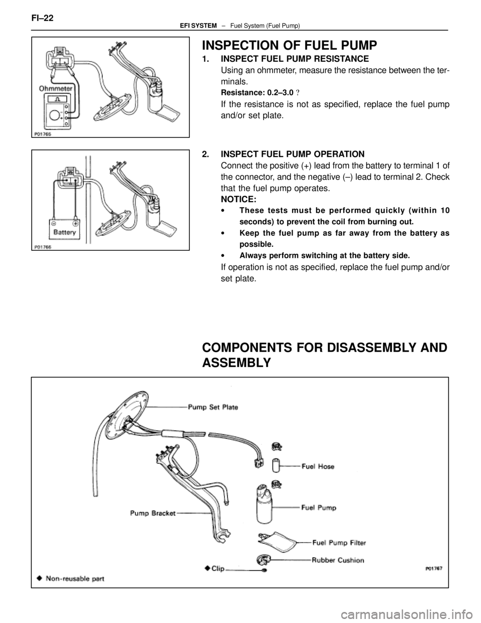
INSPECTION OF FUEL PUMP
1. INSPECT FUEL PUMP RESISTANCEUsing an ohmmeter, measure the resistance between the ter-
minals.
Resistance: 0.2±3.0 �
If the resistance is not as specified, replace the fuel pump
and/or set plate.
2. INSPECT FUEL PUMP OPERATION Connect the positive (+) lead from the battery to terminal 1 of
the connector, and the negative (±) lead to terminal 2. Check
that the fuel pump operates.
NOTICE:
w These tests must be performed quickly (within 10
seconds) to prevent the coil from burning out.
w Keep the fuel pump as far away from the battery as
possible.
w Always perform switching at the battery side.
If operation is not as specified, replace the fuel pump and/or
set plate.
COMPONENTS FOR DISASSEMBLY AND
ASSEMBLY
FI±22EFI SYSTEM ± Fuel System (Fuel Pump)
WhereEverybodyKnowsYourName
 Align the oil holes of the connecting rod and a newbushing.
(c) Using SST and a press, press in the bushing.
SST 09222±30010
(d) Using a pin hole grinder, hole the bushing to obtain the stand")
 Place the crankshaft on V±blocks.
(b) Using a dial indicator, measure the circle runout at thecenter journal.
Maximum circle runout: 0")

IllustrationPart No.Part NameNote
09268±41045Injection Measuring
Tool Set
(90268±41070)No. 4 Union
Injector
(09268±41080)No. 6 Union
Cold start Injector
(09")