Page 2666 of 4087
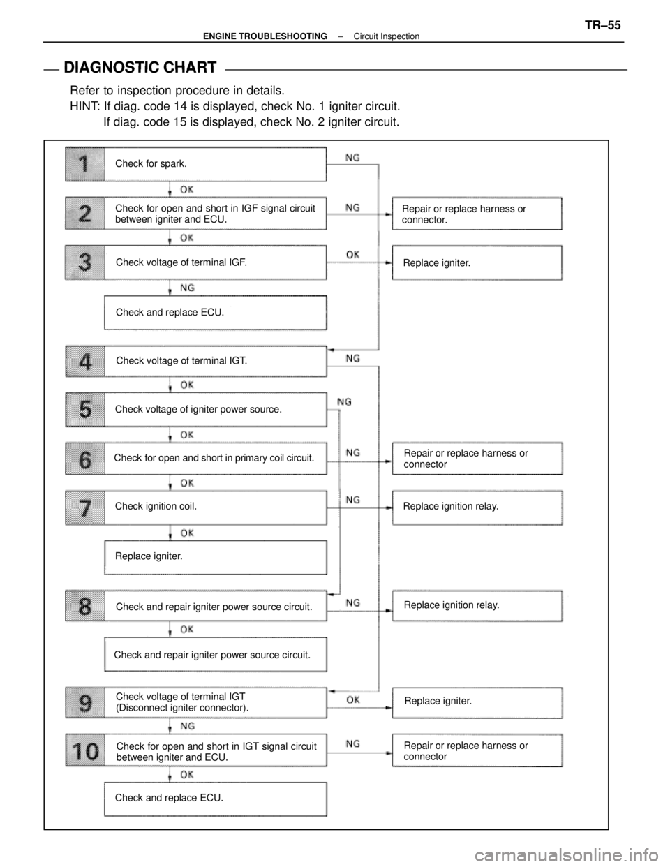
DIAGNOSTIC CHART
DIAGNOSTIC
CHART
Refer to inspection procedure in details.
HINT: If diag. code 14 is displayed, check No. 1 igniter circuit. If diag. code 15 is displayed, check No. 2 igniter circuit.
Check for spark.
Check for open and short in IGF signal circuit
between igniter and ECU.
Check voltage of terminal IGF.
Check and replace ECU.
Check voltage of terminal IGT.
Check voltage of igniter power source.
Check for open and short in primary coil circuit.
Check ignition coil.
Replace igniter.
Check and repair igniter power source circuit.
Check voltage of terminal IGT
(Disconnect igniter connector).
Check and repair igniter power source circuit. Repair or replace harness or
connector.
Replace igniter.
Repair or replace harness or
connector
Replace ignition relay.
Replace ignition relay.
Check for open and short in IGT signal circuit
between igniter and ECU.
Check and replace ECU. Repair or replace harness or
connectorReplace igniter.
±
ENGINE TROUBLESHOOTING Circuit InspectionTR±55
WhereEverybodyKnowsYourName
Page 2669 of 4087
OKNG
OKNG
6Check for open and short in harness and connector between ignition relay and \
ignition coil,
ignition coil and igniter (See page IN±27).
Repair or replace harness or connector
#Check ignition coil.
C
OK
PDisconnect ignition coil connector.
(For No. 1 ignition coil (on left bank), remove the battery)
(2) Check primary coil. Measure resistance between terminals of ignition
coil connector.
(2) Check secondary coil. Measure resistance between terminal 1 of ignition
coil connector and high±tension terminal.
Replace ignition coil.
Replace Igniter. *1
*1: When diag. code 14 is displayed, replace the igniter with 5 wire harness. (extra wire is for tachometer). When diag.
code 15 is displayed, replace the igniter with 4 wire har-
ness
TR±58±
ENGINE TROUBLESHOOTING Circuit Inspection
WhereEverybodyKnowsYourName
Page 2751 of 4087
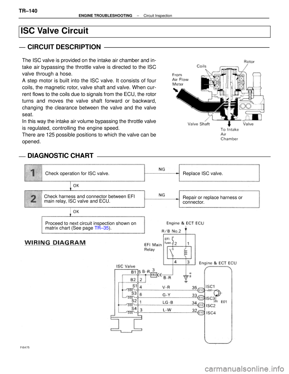
ISC Valve Circuit
CIRCUIT DESCRIPTION
The ISC valve is provided on the intake air chamber and in-
take air bypassing the throttle valve is directed to the ISC
valve through a hose.
A step motor is built into the ISC valve. It consists of four
coils, the magnetic rotor, valve shaft and valve. When cur-
rent flows to the coils due to signals from the ECU, the rotor
turns and moves the valve shaft forward or backward,
changing the clearance between the valve and the valve
seat.
In this way the intake air volume bypassing the throttle valve
is regulated, controlling the engine speed.
There are 125 possible positions to which the valve can be
opened.
DIAGNOSTIC CHARTDIAGNOSTIC CHART
Check operation for ISC valve.Replace ISC valve.
Repair or replace harness or
connector.
Proceed to next circuit inspection shown on
matrix chart (See page TR±35).
Check harness and connector between EFI
main relay, ISC valve and ECU.
TR±140±
ENGINE TROUBLESHOOTING Circuit Inspection
WhereEverybodyKnowsYourName
Page 2761 of 4087
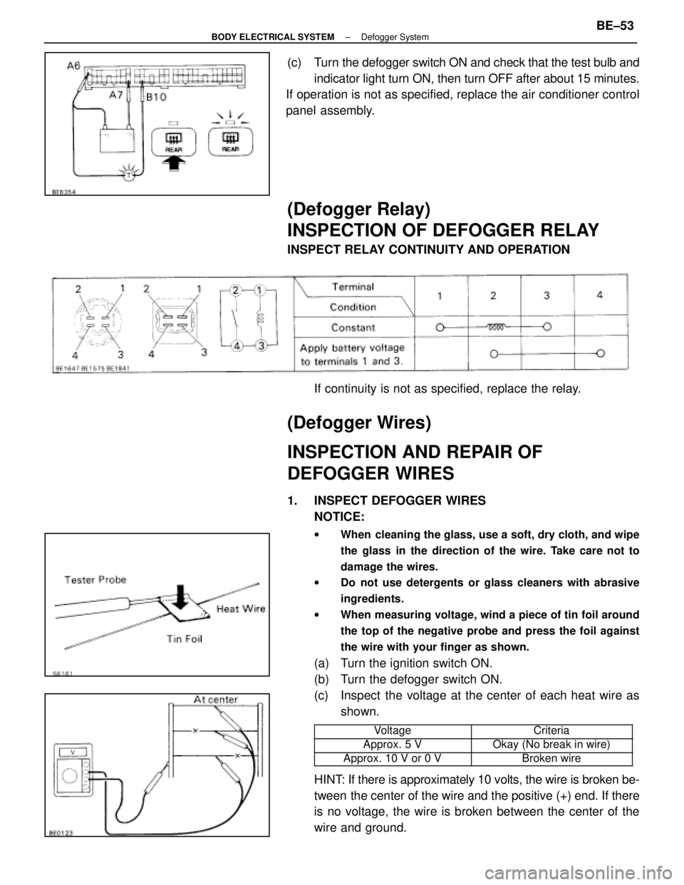
(c) Turn the defogger switch ON and check that the test bulb andindicator light turn ON, then turn OFF after about 15 minutes.
If operation is not as specified, replace the air conditioner control
panel assembly.
(Defogger Relay)
INSPECTION OF DEFOGGER RELAY
INSPECT RELAY CONTINUITY AND OPERATION
If continuity is not as specified, replace the relay.
(Defogger Wires)
INSPECTION AND REPAIR OF
DEFOGGER WIRES
1. INSPECT DEFOGGER WIRESNOTICE:
w When cleaning the glass, use a soft, dry cloth, and wipe
the glass in the direction of the wire. Take care not to
damage the wires.
w Do not use detergents or glass cleaners with abrasive
ingredients.
w When measuring voltage, wind a piece of tin foil around
the top of the negative probe and press the foil against
the wire with your finger as shown.
(a) Turn the ignition switch ON.
(b) Turn the defogger switch ON.
(c) Inspect the voltage at the center of each heat wire as
shown.
���������� ����������Voltage���������� ����������Criteria
����������Approx. 5 V����������Okay (No break in wire)���������� ����������Approx. 10 V or 0 V���������� ����������Broken wire
HINT: If there is approximately 10 volts, the wire is broken be-
tween the center of the wire and the positive (+) end. If there
is no voltage, the wire is broken between the center of the
wire and ground.
±
BODY ELECTRICAL SYSTEM Defogger SystemBE±53
WhereEverybodyKnowsYourName
Page 2778 of 4087
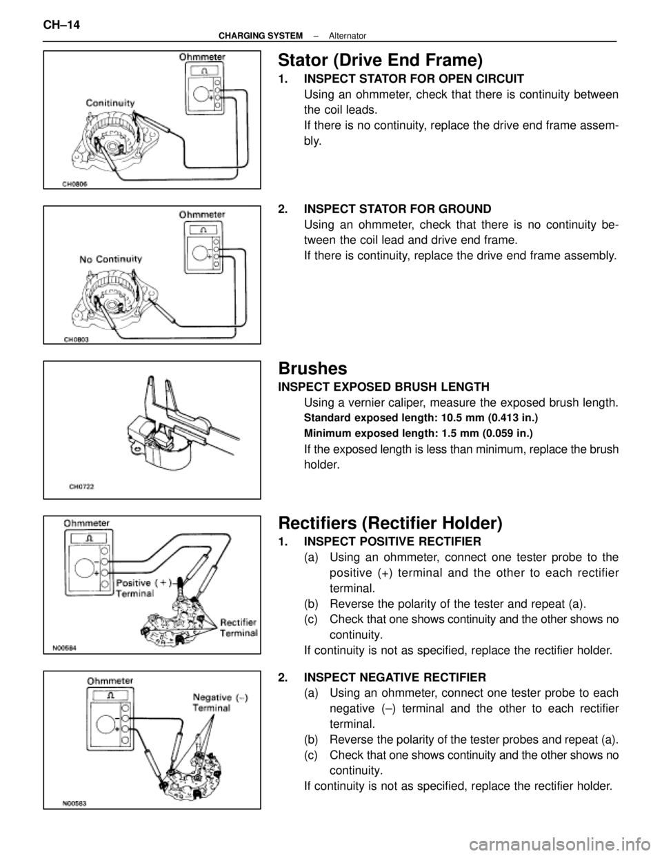
Stator (Drive End Frame)
1. INSPECT STATOR FOR OPEN CIRCUITUsing an ohmmeter, check that there is continuity between
the coil leads.
If there is no continuity, replace the drive end frame assem-
bly.
2. INSPECT STATOR FOR GROUND Using an ohmmeter, check that there is no continuity be-
tween the coil lead and drive end frame.
If there is continuity, replace the drive end frame assembly.
Brushes
INSPECT EXPOSED BRUSH LENGTHUsing a vernier caliper, measure the exposed brush length.
Standard exposed length: 10.5 mm (0.413 in.)
Minimum exposed length: 1.5 mm (0.059 in.)
If the exposed length is less than minimum, replace the brush
holder.
Rectifiers (Rectifier Holder)
1. INSPECT POSITIVE RECTIFIER(a) Using an ohmmeter, connect one tester probe to thepositive (+) terminal and the other to each rectifier
terminal.
(b) Reverse the polarity of the tester and repeat (a).
(c) Check that one shows continuity and the other shows no
continuity.
If continuity is not as specified, replace the rectifier holder.
2. INSPECT NEGATIVE RECTIFIER (a) Using an ohmmeter, connect one tester probe to each
negative (±) terminal and the other to each rectifier
terminal.
(b) Reverse the polarity of the tester probes and repeat (a).
(c) Check that one shows continuity and the other shows no
continuity.
If continuity is not as specified, replace the rectifier holder.
CH±14
±
CHARGING SYSTEM Alternator
WhereEverybodyKnowsYourName
Page 2790 of 4087
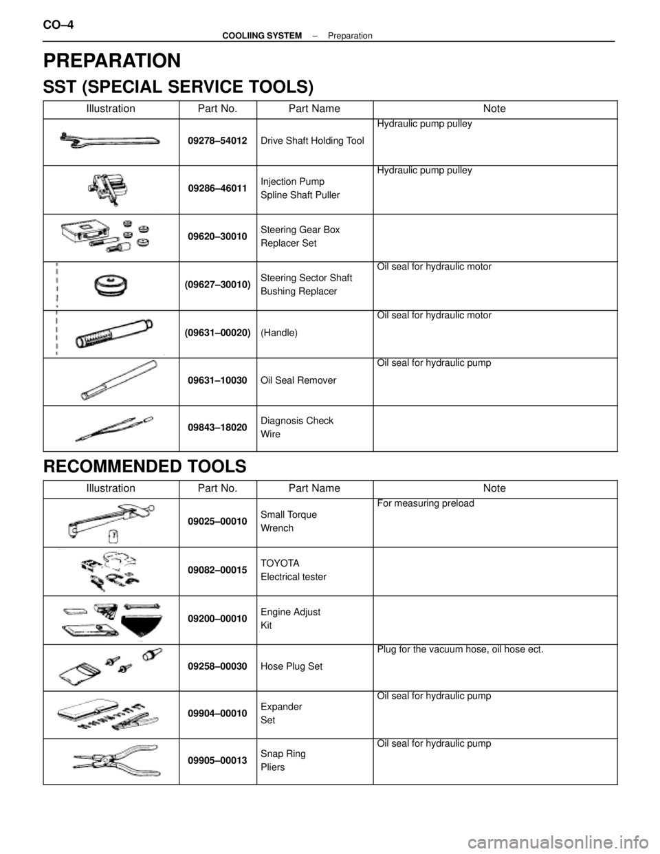
PREPARATION
SST (SPECIAL SERVICE TOOLS)
��������� ���������Illustration������ ������Part No.�������� ��������Part Name���������������� ����������������Note
��������� �
��������
���������
������ �
�����
������09278±54012
�������� �
�������
��������Drive Shaft Holding Tool
���������������� �
���������������
����������������
Hydraulic pump pulley
��������� �
��������
�
��������
���������
������ �
�����
�
�����
������09286±46011
�������� �
�������
�
�������
��������
Injection Pump
Spline Shaft Puller
���������������� �
���������������
�
���������������
����������������
Hydraulic pump pulley
��������� �
��������
�
��������
���������
������ �
�����
�
�����
������09620±30010
�������� �
�������
�
�������
��������
Steering Gear Box
Replacer Set
���������������� �
���������������
�
���������������
����������������
��������� �
��������
�
��������
���������
������ �
�����
�
�����
������(09627±30010)
�������� �
�������
�
�������
��������
Steering Sector Shaft
Bushing Replacer
���������������� �
���������������
�
���������������
����������������
Oil seal for hydraulic motor
��������� �
��������
�
��������
���������
������ �
�����
�
�����
������
(09631±00020)
�������� �
�������
�
�������
��������
(Handle)
���������������� �
���������������
�
���������������
����������������
Oil seal for hydraulic motor
��������� �
��������
�
��������
���������
������ �
�����
�
�����
������
09631±10030
�������� �
�������
�
�������
��������
Oil Seal Remover
���������������� �
���������������
�
���������������
����������������
Oil seal for hydraulic pump
��������� �
��������
�
��������
���������
������ �
�����
�
�����
������
09843±18020
�������� �
�������
�
�������
��������
Diagnosis Check
Wire���������������� �
���������������
�
���������������
����������������
RECOMMENDED TOOLS��������� �
��������
���������Illustration
������ �
�����
������Part No.
�������� �
�������
��������Part Name
���������������� �
���������������
����������������Note
��������� �
��������
�
��������
���������
������ �
�����
�
�����
������
09025±00010
�������� �
�������
�
�������
��������
Small Torque
Wrench���������������� �
���������������
�
���������������
����������������
For measuring preload
��������� �
��������
���������
������ �
�����
������09082±00015�������� �
�������
��������
TOYOTA
Electrical tester���������������� �
���������������
����������������
��������� �
��������
�
��������
���������
������ �
�����
�
�����
������09200±00010
�������� �
�������
�
�������
��������
Engine Adjust
Kit
���������������� �
���������������
�
���������������
����������������
��������� �
��������
�
��������
���������
������ �
�����
�
�����
������09258±00030
�������� �
�������
�
�������
��������Hose Plug Set
���������������� �
���������������
�
���������������
����������������
Plug for the vacuum hose, oil hose ect.
��������� �
��������
�
��������
���������
������ �
�����
�
�����
������
09904±00010
�������� �
�������
�
�������
��������
Expander
Set
���������������� �
���������������
�
���������������
����������������
Oil seal for hydraulic pump
��������� �
��������
�
��������
���������
������ �
�����
�
�����
������
09905±00013
�������� �
�������
�
�������
��������
Snap Ring
Pliers
���������������� �
���������������
�
���������������
����������������
Oil seal for hydraulic pump
CO±4±
COOLIING SYSTEM Preparation
WhereEverybodyKnowsYourName
Page 2792 of 4087
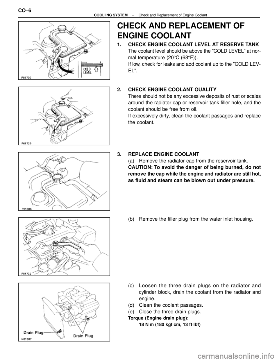
CHECK AND REPLACEMENT OF
ENGINE COOLANT
1. CHECK ENGINE COOLANT LEVEL AT RESERVE TANKThe coolant level should be above the ºCOLD LEVELº at nor-
mal temperature (20 5C (68 5F)).
If low, check for leaks and add coolant up to the ºCOLD LEV-
ELº.
2. CHECK ENGINE COOLANT QUALITY There should not be any excessive deposits of rust or scales
around the radiator cap or reservoir tank filler hole, and the
coolant should be free from oil.
If excessively dirty, clean the coolant passages and replace
the coolant.
3. REPLACE ENGINE COOLANT (a) Remove the radiator cap from the reservoir tank.
CAUTION: To avoid the danger of being burned, do not
remove the cap while the engine and radiator are still hot,
as fluid and steam can be blown out under pressure.
(b) Remove the filler plug from the water inlet housing.
(c) Loosen the three drain plugs on the radiator and
cylinder block, drain the coolant from the radiator and
engine.
(d) Clean the coolant passages.
(e) Close the three drain plugs.
Torque (Engine drain plug):
18 NVm (180 kgf Vcm, 13 ft Vlbf)
CO±6±
COOLIING SYSTEM Check and Replacement of Engine Coolant
WhereEverybodyKnowsYourName
Page 2810 of 4087
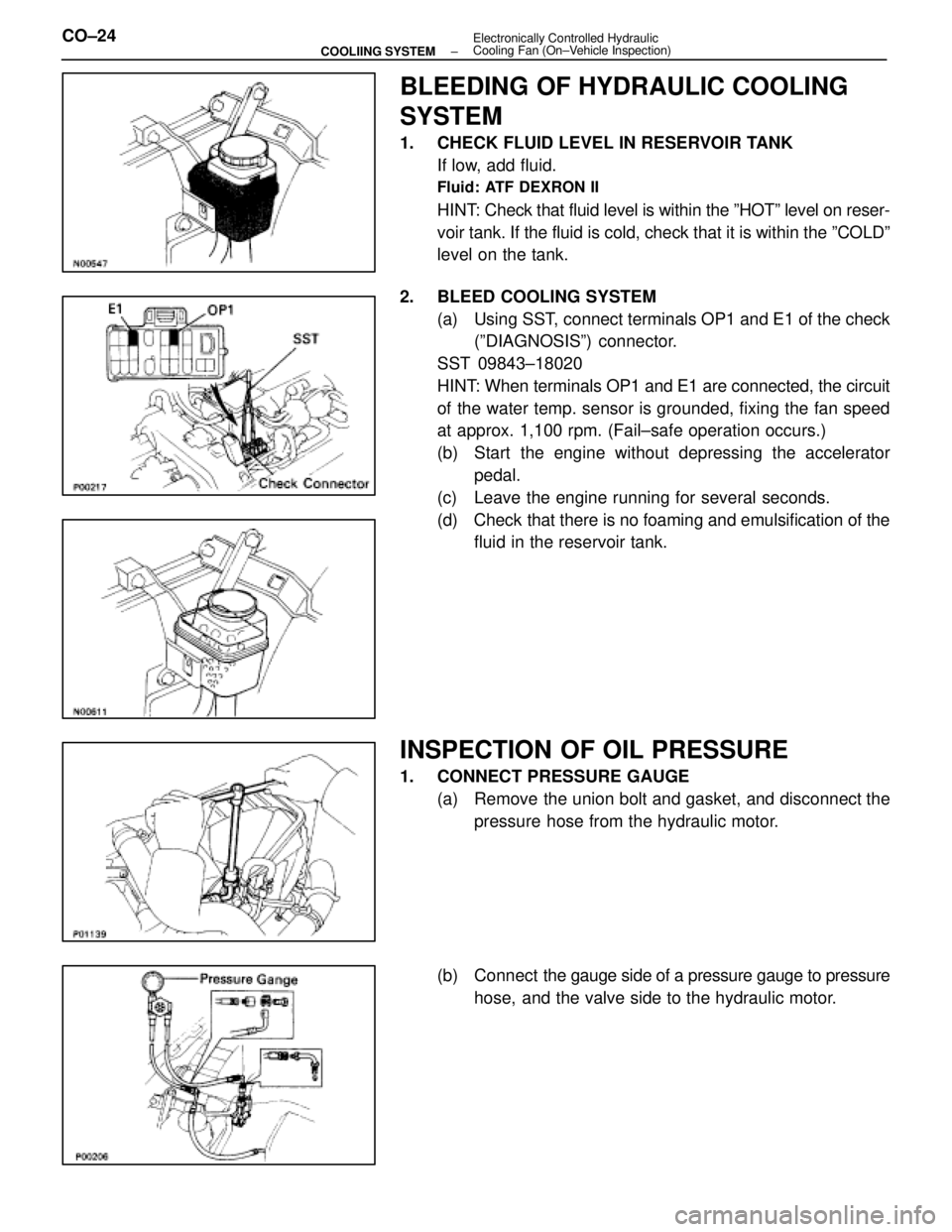
BLEEDING OF HYDRAULIC COOLING
SYSTEM
1. CHECK FLUID LEVEL IN RESERVOIR TANKIf low, add fluid.
Fluid: ATF DEXRON II
HINT: Check that fluid level is within the ºHOTº level on reser-
voir tank. If the fluid is cold, check that it is within the ºCOLDº\
level on the tank.
2. BLEED COOLING SYSTEM (a) Using SST, connect terminals OP1 and E1 of the check(ºDIAGNOSISº) connector.
SST 09843±18020
HINT: When terminals OP1 and E1 are connected, the circuit
of the water temp. sensor is grounded, fixing the fan speed
at approx. 1,100 rpm. (Fail±safe operation occurs.)
(b) Start the engine without depressing the accelerator pedal.
(c) Leave the engine running for several seconds.
(d) Check that there is no foaming and emulsification of the fluid in the reservoir tank.
INSPECTION OF OIL PRESSURE
1. CONNECT PRESSURE GAUGE
(a) Remove the union bolt and gasket, and disconnect thepressure hose from the hydraulic motor.
(b) Connect the gauge side of a pressure gauge to pressure
hose, and the valve side to the hydraulic motor.
CO±24
±
COOLIING SYSTEM Electronically Controlled Hydraulic
Cooling Fan (On±Vehicle Inspection)
WhereEverybodyKnowsYourName