Page 3366 of 4087

ISC Valve Circuit
CIRCUIT DESCRIPTION
The ISC valve is provided on the intake air chamber and in-
take air bypassing the throttle valve is directed to the ISC
valve through a hose.
A step motor is built into the ISC valve. It consists of four
coils, the magnetic rotor, valve shaft and valve. When cur-
rent flows to the coils due to signals from the ECU, the rotor
turns and moves the valve shaft forward or backward,
changing the clearance between the valve and the valve
seat.
In this way the intake air volume bypassing the throttle valve
is regulated, controlling the engine speed.
There are 125 possible positions to which the valve can be
opened.
DIAGNOSTIC CHARTDIAGNOSTIC CHART
Check operation for ISC valve.Replace ISC valve.
Repair or replace harness or
connector.
Proceed to next circuit inspection shown on
matrix chart (See page TR±35).
Check harness and connector between EFI
main relay, ISC valve and ECU.
TR±140±
ENGINE TROUBLESHOOTING Circuit Inspection
WhereEverybodyKnowsYourName
Page 3397 of 4087

YESNO
NOYES
YES
NO
OKNG
BASIC INSPECTION
When the normal code is displayed in the diagnostic code check, troubleshoot\
ing should be performed in the
order for all possible circuits to be considered as the causes of the pr\
oblems.
In many cases, by carrying out the basic engine check shown in the follo\
wing flow chart, the location causing
the problem can be found quickly and ef ficiently. Therefore, use of this check is essential in engine troubleshoot-
ing.
1Is battery voltage 11 V or more when engine is stopped?
Charge or replace battery.
2Is engine cracnked?
Proceed to matrix to matrix chart of problem
symptoms on page TR±35.
3Does engine start?
Go to step [7]
4Check air filter
C
Hint
PRemove air filter
Visially check that the air cleaner element is not exces-
sively damaged or oily.
If necessary, clean element with compressed air. First
blow from inside thoroughly, then blow off outside of ele-
ment.
Repair or replace
Go to Step [5].
TR±24±
ENGINE TROUBLESHOOTING Basic Inspection
WhereEverybodyKnowsYourName
Page 3398 of 4087
 Warm up engine at normal operating temperature.
(2) Switched off all accessories.
(3) Switched off air conditioner.
(4) Shift transmission into ªNº range.
(5)")
OKNG
OKNG
5Check idle speed.
C
OK
P(1) Warm up engine at normal operating temperature.
(2) Switched off all accessories.
(3) Switched off air conditioner.
(4) Shift transmission into ªNº range.
(5) Connect tachometer test probe to terminal IG � of
check connector, and set the tachometer to the
4±cylinder range.
Check idle speed.
Idle speed: 650 ~ 750 rpm
Caution:
�NEVER allow tachometer test probe to touch
ground as it could result in damage to igniter
and/or coil.
�As some tachometers are not compatible with
this ignition system, we recommended that you
confirm compatibility of your unit before use.
Proceed to matrix chart of problem symptoms on page
TR±35 .
6Check ignition timing.
C
OK
P(1) Warm up engine at normal operating temperture.
(2) Shift transmission into ªNº range.
(3) Keep the engine speed at idle.
(4) Using SST, connect terminals TE1 and E1 of check
connector.
SST 09843±18020
(5) Using a timing light. connect the tester to No. 6 high±tension cord.
Check ignition timing.
Ignition Timing: 8±12 � BTDC at idle
Proceed to page IG±28 and continue to troubleshoot.
Proceed to matix chart of problem symptoms on
page TR±35 .
±
ENGINE TROUBLESHOOTING Basic InspectionTR±25
WhereEverybodyKnowsYourName
Page 3438 of 4087
DIAGNOSTIC CHART
WIRING DIAGRAM
Check resistance of each pickup coils in
distributor
Check for open and short in harness and
connector between ECU and distributor.
Check air gap.
Check and replace ECU.
Replace distributor.
Repair or rep lace harness or connector.
Replace distributor
±
ENGINE TROUBLESHOOTING Circuit InspectionTR±47
WhereEverybodyKnowsYourName
Page 3439 of 4087
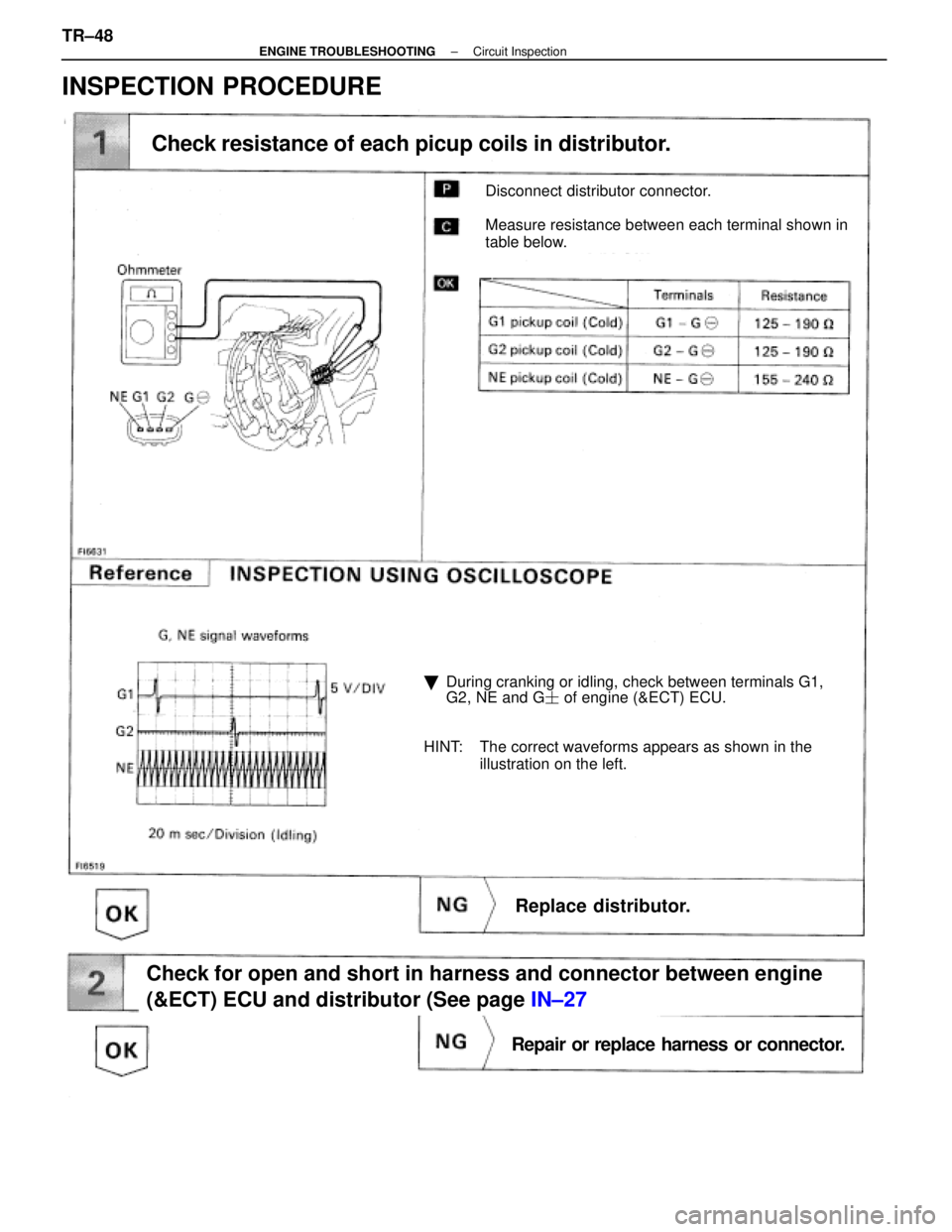
Disconnect distributor connector.
Measure resistance between each terminal shown in
table below.
Check resistance of each picup coils in distributor.
�During cranking or idling, check between terminals G1,
G2, NE and G � of engine (&ECT) ECU.
HINT: The correct waveforms appears as shown in the illustration on the left.
Replace distributor.
Check for open and short in harness and connector between engine
(&ECT) ECU and distributor (See page IN±27
Repair or replace harness or connector.
INSPECTION PROCEDURE
TR±48±
ENGINE TROUBLESHOOTING Circuit Inspection
WhereEverybodyKnowsYourName
Page 3440 of 4087
Remove distributor cap & rotor.
Using SST (G1 and G2 pickups) and a thikness gauge
(NE pickup). measure the air gap between the signal
rotor projection and pickup coil.
SST 09240±00020 fro G1 and G2 pickups
Air gap: 0.2±0.4 mm (0.008±0.016 in.)
Replace distributor.
Check and replace engine (& ECT) ECU.
±
ENGINE TROUBLESHOOTING Circuit InspectionTR±49
WhereEverybodyKnowsYourName
Page 3449 of 4087

DIAGNOSTIC CHART
DIAGNOSTIC
CHART
Refer to inspection procedure in details.
HINT: If diag. code 14 is displayed, check No. 1 igniter circuit. If diag. code 15 is displayed, check No. 2 igniter circuit.
Check for spark.
Check for open and short in IGF signal circuit
between igniter and ECU.
Check voltage of terminal IGF.
Check and replace ECU.
Check voltage of terminal IGT.
Check voltage of igniter power source.
Check for open and short in primary coil circuit.
Check ignition coil.
Replace igniter.
Check and repair igniter power source circuit.
Check voltage of terminal IGT
(Disconnect igniter connector).
Check and repair igniter power source circuit. Repair or replace harness or
connector.
Replace igniter.
Repair or replace harness or
connector
Replace ignition relay.
Replace ignition relay.
Check for open and short in IGT signal circuit
between igniter and ECU.
Check and replace ECU. Repair or replace harness or
connectorReplace igniter.
±
ENGINE TROUBLESHOOTING Circuit InspectionTR±55
WhereEverybodyKnowsYourName
Page 3452 of 4087
OKNG
OKNG
6Check for open and short in harness and connector between ignition relay and \
ignition coil,
ignition coil and igniter (See page IN±27).
Repair or replace harness or connector
#Check ignition coil.
C
OK
PDisconnect ignition coil connector.
(For No. 1 ignition coil (on left bank), remove the battery)
(2) Check primary coil. Measure resistance between terminals of ignition
coil connector.
(2) Check secondary coil. Measure resistance between terminal 1 of ignition
coil connector and high±tension terminal.
Replace ignition coil.
Replace Igniter. *1
*1: When diag. code 14 is displayed, replace the igniter with 5 wire harness. (extra wire is for tachometer). When diag.
code 15 is displayed, replace the igniter with 4 wire har-
ness
TR±58±
ENGINE TROUBLESHOOTING Circuit Inspection
WhereEverybodyKnowsYourName

 and a thikness gauge
(NE pickup). measure the air gap between the signal
rotor projection and pickup coil.
SST 09240±00020 fro G1 and G2")
.
Repair or replace harness or connector
#Check ign")