Page 3810 of 4087

SERVICE HINTS FOR REFRIGERANT LEAK DETECTIONPage 1 of 3
Use of electronic leak detectors for checking A/C systems refrigerant leaka\
ge is the only
method approved by TMS. This type of leak detector is sensitive not onl\
y to refrigerant, but
also sensitive to numerous petrochemical substances (motor oil, gasolin\
e, solvents, etc.)
commonly found in a repair shop environment. Because this sensitivity c\
ould diminish the leak
detector 's capacity for accurate leak detection, some service hints have been pro\
vided to help
increase the accuracy of your diagnosis.
SERVICE HINTS:
1. Visual Inspection: Do a quick visual inspection under the hood for signs of refrigerant
leakage. Check for areas of heavy oil leakage at block and piping joint\
s. Many times
these areas have accumulated road dust and dirt.
2. Inspection with leak detector: NOTE: Make sure the system is fully charged. Operate
the system to increase refrigerant pressure. Shut the system off before inspecting with
leak detector.
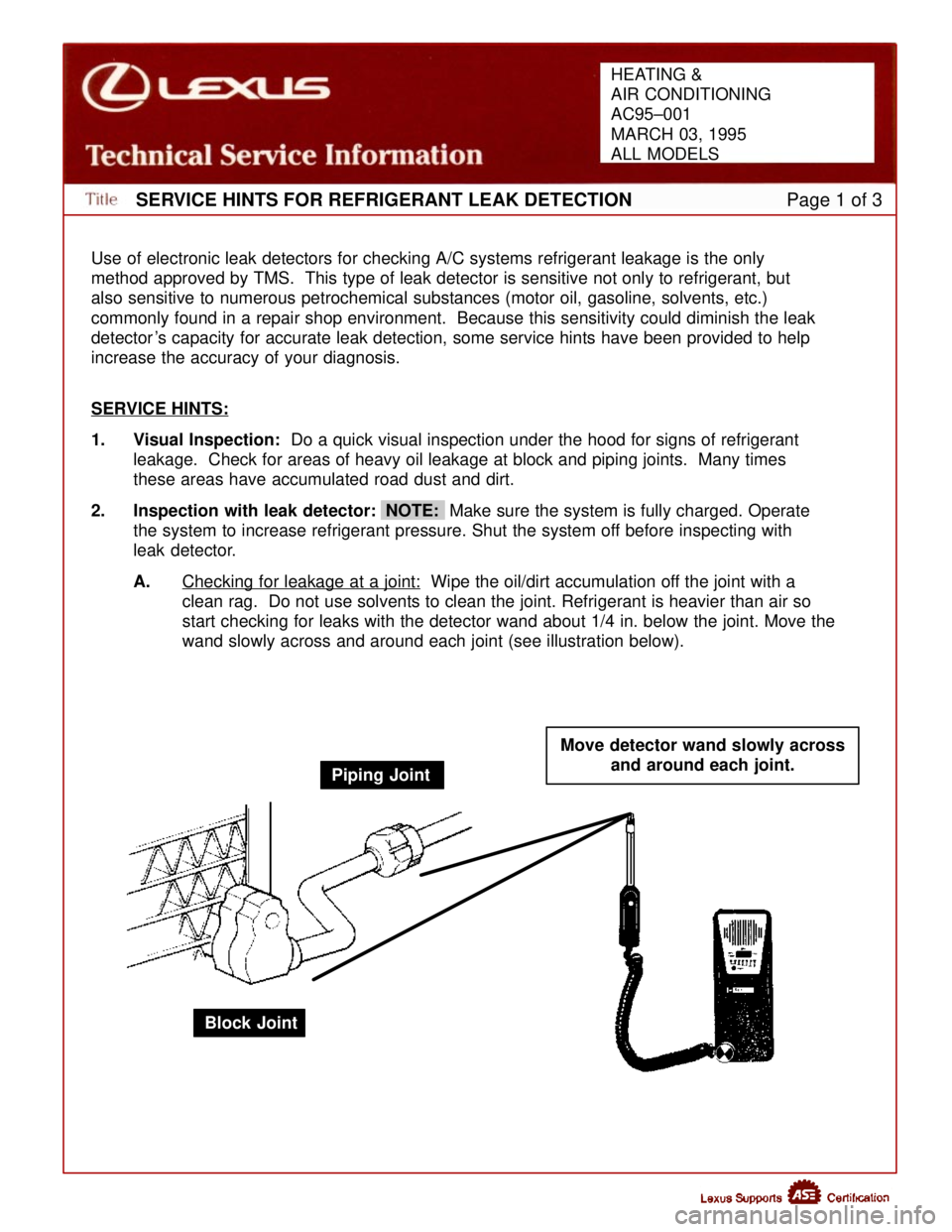
A. Checking for leakage at a joint:
Wipe the oil/dirt accumulation off the joint with a
clean rag. Do not use solvents to clean the joint. Refrigerant is heavi\
er than air so
start checking for leaks with the detector wand about 1/4 in. below the \
joint. Move the
wand slowly across and around each joint (see illustration below).
Piping Joint Move detector wand slowly across
and around each joint.
Block Joint
HEATING &
AIR CONDITIONING
AC95±001
MARCH 03, 1995
ALL MODELS
WhereEverybodyKnowsYourName
Page 3811 of 4087

SERVICE HINTS FOR REFRIGERANT LEAK DETECTIONPage 2 of 3
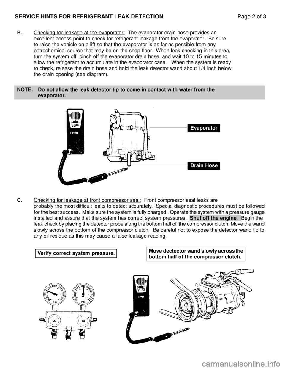
B.Checking for leakage at the evaporator: The evaporator drain hose provides an
excellent access point to check for refrigerant leakage from the evapora\
tor. Be sure
to raise the vehicle on a lift so that the evaporator is as far as possi\
ble from any
petrochemical source that may be on the shop floor. When leak checking in this area,
turn the system off, pinch off the evaporator drain hose, and wait 10 to 15 minutes to
allow the refrigerant to accumulate in the evaporator case. When the s\
ystem is ready
to check, release the drain hose and hold the leak detector wand about 1\
/4 inch below
the drain opening (see diagram).
NOTE: Do not allow the leak detector tip to come in contact with water from th\
e evaporator.
C. Checking for leakage at front compressor seal:
Front compressor seal leaks are
probably the most difficult leaks to detect accurately. Special diagnostic procedures must be followed
for the best success. Make sure the system is fully charged. Operate the \
system with a pressure gauge
installed and assure that the system has correct system pressures. Shut off the engine. Begin the
leak check by placing the detector probe along the bottom half of the compr\
essor clutch. Move the wand
slowly across the bottom of the compressor clutch. Be careful not to expose t\
he detector wand tip to
any oil residue as this may cause a false leakage reading.
Evaporator
Drain Hose
Verify correct system pressure. Move dectector wand slowly across the
bottom half of the compressor clutch.
WhereEverybodyKnowsYourName
Page 3812 of 4087
SERVICE HINTS FOR REFRIGERANT LEAK DETECTIONPage 3 of 3
D. Checking for leakage at service valves or pressure switches:
Small accumulations of refrigerant gas under the service valve caps or p\
ressure switch connectors is
normal. When checking for leaks at these points, use the following proc\
edures to assure the highest
accuracy:
1. Remove the service valve cap or pressure switch connector.
2. Allow the service valve or pressure switch to remain uncapped for approx\
imately
20 minutes. This will allow the air to circulate and carry away the acc\
umulated
refrigerant. (This is a good time to leak check other areas of the syst\
em).
3. Do not use compressed air to flush out the service valve or pressure swi\
tch
cavity. Petroleum residue from inline oilers or compressor lubrication may ca\
use
false readings.
WhereEverybodyKnowsYourName
Page 3817 of 4087

SUSPENSION BALL JOINT INSPECTION ± PG012-02 October 11, 2002
Page 4 of 5
B. Move the lower arm by hand (All
models with strut type suspension
and some models with wish±bone
type suspension):
a. Lift up the vehicle.
b. Inspect the free play while moving the lower arm up and
down at a force of 67 lbf
(294 N, 30 kgf).
2. Inspect Upper Ball Joint Play Move the upper arm by hand (Models
where the LOWER control arm are
linked by a torsion bar, and all models
using a coil spring.
A. Remove the front tire.
B. Inspect the free play while moving the upper arm up and down at a
force of 67 lbf (294 N, 30 kgf).
3. Inspect the Suspension Arm Ball Joint Free Play
A. Lift up the vehicle.
B. Inspect the free play while moving the control arm by hand.
(Reference)
Free Play Inspection Method
(Gauge Installation) � Position the dial gauge between the
arm (upper or lower) and the knuckle,
and measure free play.
(This illustration shows how to
measure free play for vehicles with
double wishbone type suspension
with coil spring).
Inspect Ball Joint Dust Cover
Check for cracks and grease leaks on the
dust cover (boots).Free Play
Inspection
(Continued)
WhereEverybodyKnowsYourName
Page 3863 of 4087
221
1E
19 1E 14
1H
11 1H 7
IK1
16 IK1 17
2
L
LH
TURN
A
5A 16 B 17 B16
C
23
1 IK2
5 IK2
4
SEAT BELT
ABS
TRAC
TRAC OFF
A
19 A 7B15 B 5B1
W±B
LG±R W
V
LG±R
TO ABS AND
TRACTION ECU
(
IND )
TO ABS AND
TRACTION ECU
( WT ) G
W G±Y
G±B
G±B G±Y WG
R±W
FROM
A/T INDICATOR SW
OIL PRESSURE SW RH
Y±B
O2
COMBINATION METER C12 , C 1 3
,C14
ABC
I23
WW
TO TDCL (
TRC )
IK 2
9
Y±B
I22
L±Y
IO1
7
L±Y
I23
L
L±Y
TO ENGINE AND
ECT ECU
(
W ) L±Y
TO CHAK
CONNECTOR (
W )
L
TO ABS AND
TRACTION ECU
(
WA ) L
TO CHECK
CONNECTOR (
LP )
IK2
2
L
W
1E
1
SEAT BELT WARNING
RELAY [INTEGRATION RELAY] CHECK ENGINE
B
3
L±Y
IK1
20
FROM TURN
SIGNAL FLASHER
3D
10
3A2
3A 1
W±B
G±O
OIL
G±O
WhereEverybodyKnowsYourName
Page 3868 of 4087

26
ELECTRICAL WIRING ROUTING
Position of Parts in Engine Compartment
A 1 A/C Ambient Temp. Sensor E 1 ECT Solenoid
A 2 A/C Lock Sensor and A/C Magnetic Clutch E 2 EFI Water Temp. Sensor
A 3 A/C High Pressure SW E 3 EGR Gas Temp. Sensor (for USA Spec.)
A 4 ABS Actuator E 5 Engine Hood Courtesy SW
A 5 ABS Actuator (w/ Traction Control) E 6 Engine Oil Level Warning SW
A 6 ABS Actuator (w/ Traction Control)
A 7 ABS Speed Sensor Front LH F 1 Front Airbag Sensor LH
A 8 ABS Speed Sensor Front RH F 2 Front Airbag Sensor RH
A 9 Air Flow Meter F 3 Front Clearance Light LH
A 10 Alternator F 4 Front Clearance Light RH
A 11 Alternator F 5Front Side Marker Light LH
A 33 ABS Actuator (w/o Traction Control) F 6 Front Side Marker Light RH F 7 Front Turn Signal Light LH
B 1 Brake Fluid Level SW F 8 Front Turn Signal Light RH
B 6 Back±Up Light SW (for M/T) F 9 Fuse Block
C 3 Check Connector H 1 Headlight Hi LH
C 6 Cornering Light LH H 2 Headlight Hi RH
C 7 Cornering Light RH H 3 Headlight Lo LH
C 8 Cruise Control Actuator H 4 Headlight Lo RH H 5 Horn LH
D 13 Distributor H 6 Horn RH
WhereEverybodyKnowsYourName
Page 3919 of 4087

236
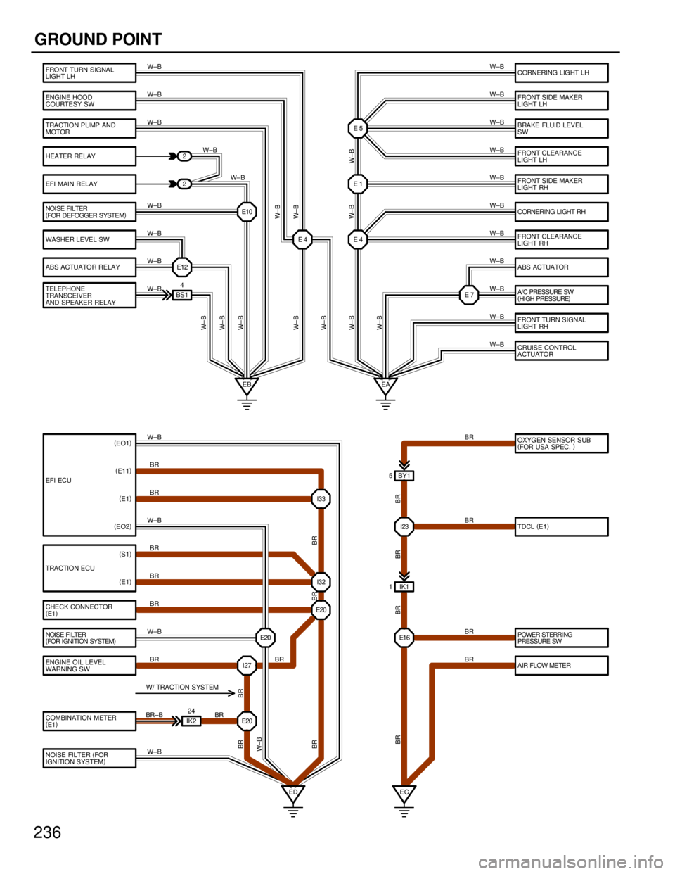
GROUND POINT
FRONT TURN SIGNAL
LIGHT LH
ENGINE HOOD
COURTESY SW
TRACTION PUMP AND
MOTOR
HEATER RELAY
ABS ACTUATOR RELAY
TELEPHONE
TRANSCEIVER
AND SPEAKER RELAY
ENGINE OIL LEVEL
WARNING SW
COMBINATION METER
(E1 )
EFI ECU
TRACTION ECU
CHECK CONNECTOR
(
E1 ) CORNERING LIGHT LH
FRONT SIDE MAKER
LIGHT LH
BRAKE FLUID LEVEL
SW
FRONT CLEARANCE
LIGHT LH
FRONT SIDE MAKER
LIGHT RH
FRONT CLEARANCE
LIGHT RH
ABS ACTUATOR
FRONT TURN SIGNAL
LIGHT RH
CRUISE CONTROL
ACTUATOR
OXYGEN SENSOR SUB
(
FOR USA SPEC. )
TDCL (
E1 )
WASHER LEVEL SW EFI MAIN RELAY
CORNERING LIGHT RH
A/C PRESSURE SW
(HI GH PRESSURE )
AIR FLOW METER POWER STERRI NG
PRESSURE SW
NOISE FI LTER
(
FOR IGNI TION SYSTEM ) E4
E10
E12 2
2
BS1 4 E4
E7
E1 E5
EB EA I23
I33
E1 6
I32
E20
E20
E20
IK2 24
ED EC IK1
1 BY1
5
W±B
W±B
W±B
W±B
W±B
W±B
W±B
W±B
W± B W±B
W±B
W±B
W±B
W±B
W±B
W±B
W±B
W±B
W±B
W±B
W±B BR
BR
W±B BR
BR
BR
W±B BR
BR±B BR BR
BR
BR
W± B
W± B
W± B
W± B
W± B
W± B
W± B
W±B
W±B
BR
BR
BR
BR BR
BR
BR
W±B
BR BR
BR
( EO1 )
( E11 )
( E1 )
( EO2 )
I27BR
(
S1 )
( E1 )
NOISE FILTER (
FOR
IGNITION SYSTEM )W±B
W/ TRACTION SYSTEM
NOI SE FILTER
(
FOR DEFOGGER SYSTEM )
W±B
W±B
WhereEverybodyKnowsYourName
Page 3954 of 4087
567 8
1LEXUSSC300(
Cont ' d )
2EC2 1EC2
7IJ1
1
345
12
B±O
B B
B±O
21
B±O
B±O
BL
B±O
W± L
B±O
W±Y
Y± G
W±Y
Y±G To Engine and ECT ECU º IGT1º < 2±8>
To Engine and ECT ECU º IGF1º < 2±8>
To Check Connec tor º IG±º < 2±4>
IGF IGT +B C±
TAC
I2
IGNITER
NO. 1
I4
IGNITION COIL
NO. 1DI STRI B UT OR
N3
NOISE FILTER
(
for Ignition System )
Ignition
B±O
8IK1 ToComb. MeterºTACHOº<21±7>
B± OB
WhereEverybodyKnowsYourName