Page 2811 of 4087
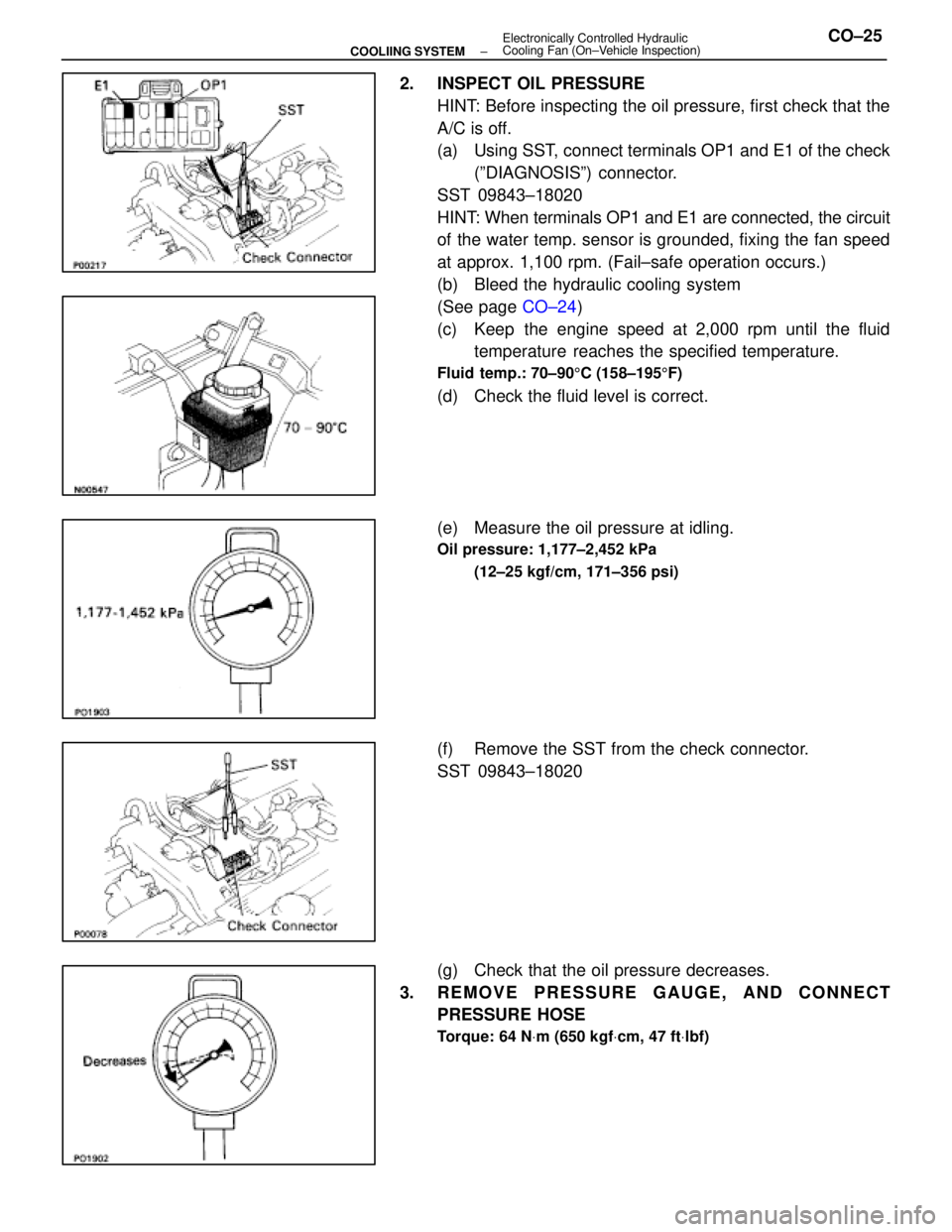
2. INSPECT OIL PRESSUREHINT: Before inspecting the oil pressure, first check that the
A/C is off.
(a) Using SST, connect terminals OP1 and E1 of the check(ºDIAGNOSISº) connector.
SST 09843±18020
HINT: When terminals OP1 and E1 are connected, the circuit
of the water temp. sensor is grounded, fixing the fan speed
at approx. 1,100 rpm. (Fail±safe operation occurs.)
(b) Bleed the hydraulic cooling system
(See page CO±24)
(c) Keep the engine speed at 2,000 rpm until the fluid temperature reaches the specified temperature.
Fluid temp.: 70±90 5C (158±195 5F)
(d) Check the fluid level is correct.
(e) Measure the oil pressure at idling.
Oil pressure: 1,177±2,452 kPa
(12±25 kgf/cm, 171±356 psi)
(f) Remove the SST from the check connector.
SST 09843±18020
(g) Check that the oil pressure decreases.
3. REMOVE PRESSURE GAUGE, AND CONNECT PRESSURE HOSE
Torque: 64 N Vm (650 kgf Vcm, 47 ft Vlbf)
±
COOLIING SYSTEM Electronically Controlled Hydraulic
Cooling Fan (On±Vehicle Inspection)CO±25
WhereEverybodyKnowsYourName
Page 2820 of 4087
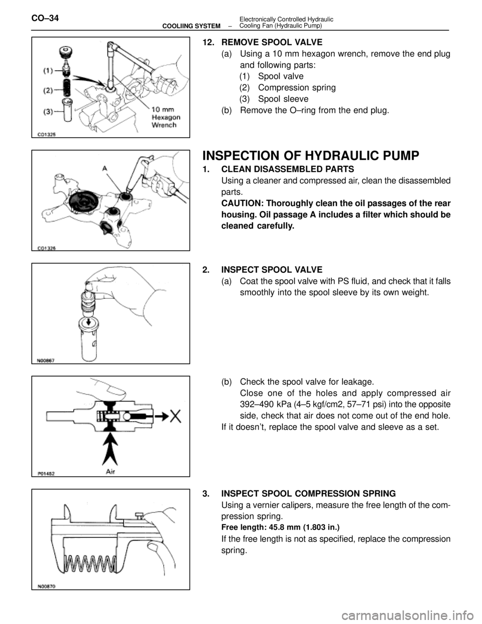
12. REMOVE SPOOL VALVE(a) Using a 10 mm hexagon wrench, remove the end plugand following parts:
(1) Spool valve
(2) Compression spring
(3) Spool sleeve
(b) Remove the O±ring from the end plug.
INSPECTION OF HYDRAULIC PUMP
1. CLEAN DISASSEMBLED PARTS Using a cleaner and compressed air, clean the disassembled
parts.
CAUTION: Thoroughly clean the oil passages of the rear
housing. Oil passage A includes a filter which should be
cleaned carefully.
2. INSPECT SPOOL VALVE (a) Coat the spool valve with PS fluid, and check that it falls
smoothly into the spool sleeve by its own weight.
(b) Check the spool valve for leakage. Close one of the holes and apply compressed air
392±490 kPa (4±5 kgf/cm2, 57±71 psi) into the opposite
side, check that air does not come out of the end hole.
If it doesn't, replace the spool valve and sleeve as a set.
3. INSPECT SPOOL COMPRESSION SPRING Using a vernier calipers, measure the free length of the com-
pression spring.
Free length: 45.8 mm (1.803 in.)
If the free length is not as specified, replace the compression
spring.
CO±34
±
COOLIING SYSTEM Electronically Controlled Hydraulic
Cooling Fan (Hydraulic Pump)
WhereEverybodyKnowsYourName
Page 2841 of 4087
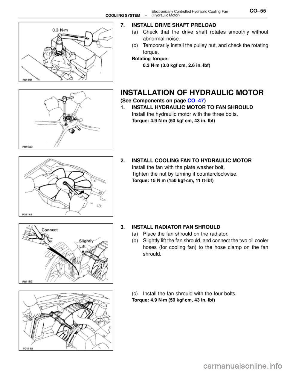
7. INSTALL DRIVE SHAFT PRELOAD(a) Check that the drive shaft rotates smoothly withoutabnormal noise.
(b) Temporarily install the pulley nut, and check the rotating
torque.
Rotating torque:
0.3 N Vm (3.0 kgf Vcm, 2.6 in. Vlbf)
INSTALLATION OF HYDRAULIC MOTOR
(See Components on page CO±47)
1. INSTALL HYDRAULIC MOTOR TO FAN SHROULD Install the hydraulic motor with the three bolts.
Torque: 4.9 N Vm (50 kgf Vcm, 43 in. Vlbf)
2. INSTALL COOLING FAN TO HYDRAULIC MOTOR
Install the fan with the plate washer bolt.
Tighten the nut by turning it counterclockwise.
Torque: 15 N Vm (150 kgf Vcm, 11 ft Vlbf)
3. INSTALL RADIATOR FAN SHROULD
(a) Place the fan shrould on the radiator.
(b) Slightly lift the fan shrould, and connect the two oil cooler
hoses (for cooling fan) to the hose clamp on the fan
shrould.
(c) Install the fan shrould with the four bolts.
Torque: 4.9 N Vm (50 kgf Vcm, 43 in. Vlbf)
±
COOLIING SYSTEM Electronically Controlled Hydraulic Cooling Fan
(Hydraulic Motor)CO±55
WhereEverybodyKnowsYourName
Page 2845 of 4087
4. REMOVE OIL COOLERRemove the three bolts and oil cooler.
INSPECTION OF OIL COOLER
INSPECT OIL COOLER
Check the oil cooler for damage or clogging.
If necessary, replace the oil cooler.
INSTALLATION OF OIL COOLER
(See Components on page CO±58)
1. INSTALL OIL COOLER Install the oil cooler with the three bolts.
Torque: 18 N Vm (180 kgf Vcm, 13 ft Vlbf)
2. CONNECT HOSES FROM OIL COOLER
Connect the following hoses:(1) Inlet hose (from reservoir tank)
(2) Outlet hose (from hydraulic motor)
3. INSTALL PS OIL COOLER Install the oil cooler with the two bolts.
4. REMOVE FENDER LINER
5. FILL COOLING FAN RESERVOIR TANK WITH FLUID
(See pages CO±23 and 24)
6. START ENGINE AND CHECK FOR LEAKS
±
COOLIING SYSTEM Electronically Controlled Hydraulic
Cooling Fan (Oil Cooler)CO±59
WhereEverybodyKnowsYourName
Page 2907 of 4087
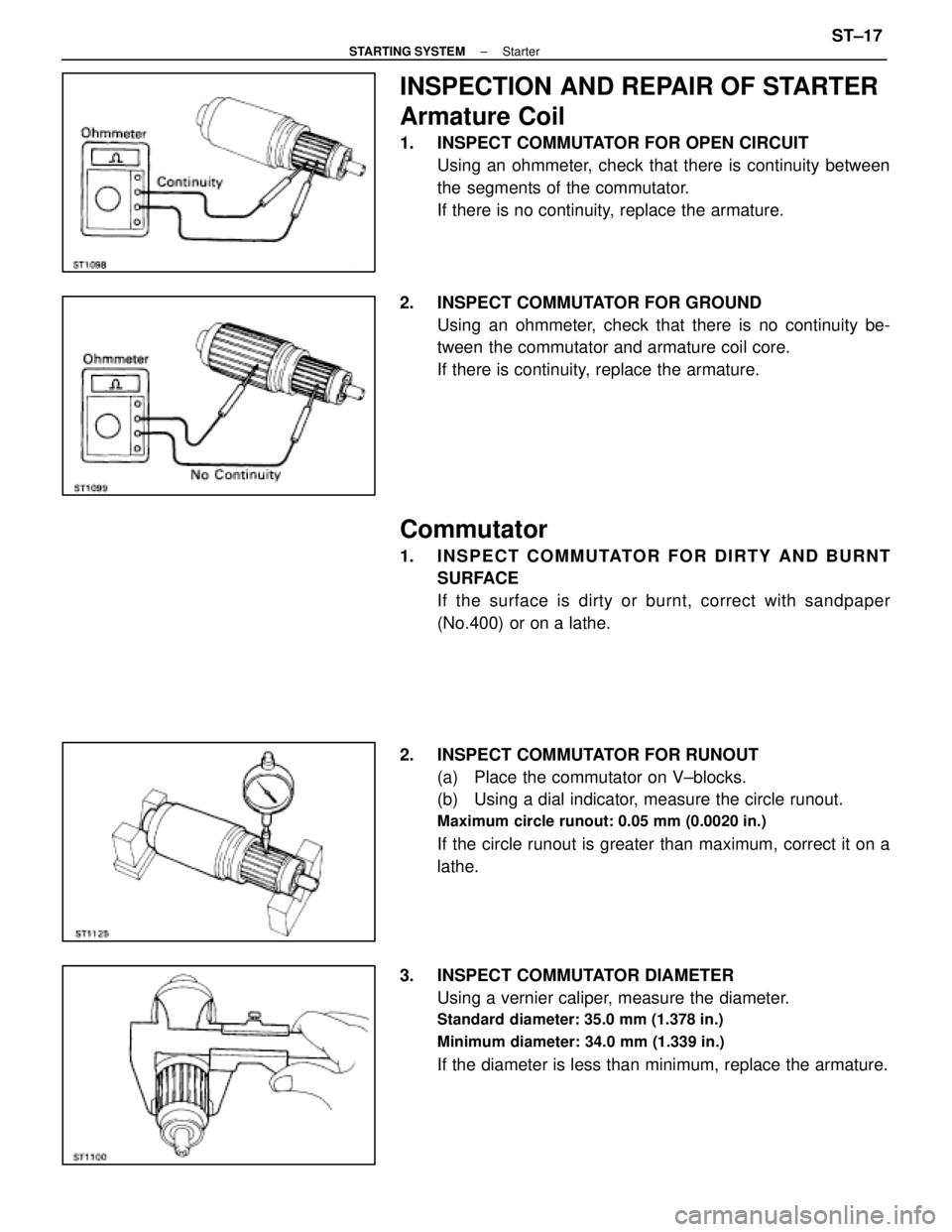
INSPECTION AND REPAIR OF STARTER
Armature Coil
1. INSPECT COMMUTATOR FOR OPEN CIRCUITUsing an ohmmeter, check that there is continuity between
the segments of the commutator.
If there is no continuity, replace the armature.
2. INSPECT COMMUTATOR FOR GROUND Using an ohmmeter, check that there is no continuity be-
tween the commutator and armature coil core.
If there is continuity, replace the armature.
Commutator
1. INSPECT COMMUTATOR FOR DIRTY AND BURNTSURFACE
If the surface is dirty or burnt, correct with sandpaper
(No.400) or on a lathe.
2. INSPECT COMMUTATOR FOR RUNOUT (a) Place the commutator on V±blocks.
(b) Using a dial indicator, measure the circle runout.
Maximum circle runout: 0.05 mm (0.0020 in.)
If the circle runout is greater than maximum, correct it on a
lathe.
3. INSPECT COMMUTATOR DIAMETER Using a vernier caliper, measure the diameter.
Standard diameter: 35.0 mm (1.378 in.)
Minimum diameter: 34.0 mm (1.339 in.)
If the diameter is less than minimum, replace the armature.
±
STARTING SYSTEM StarterST±17
WhereEverybodyKnowsYourName
Page 2908 of 4087
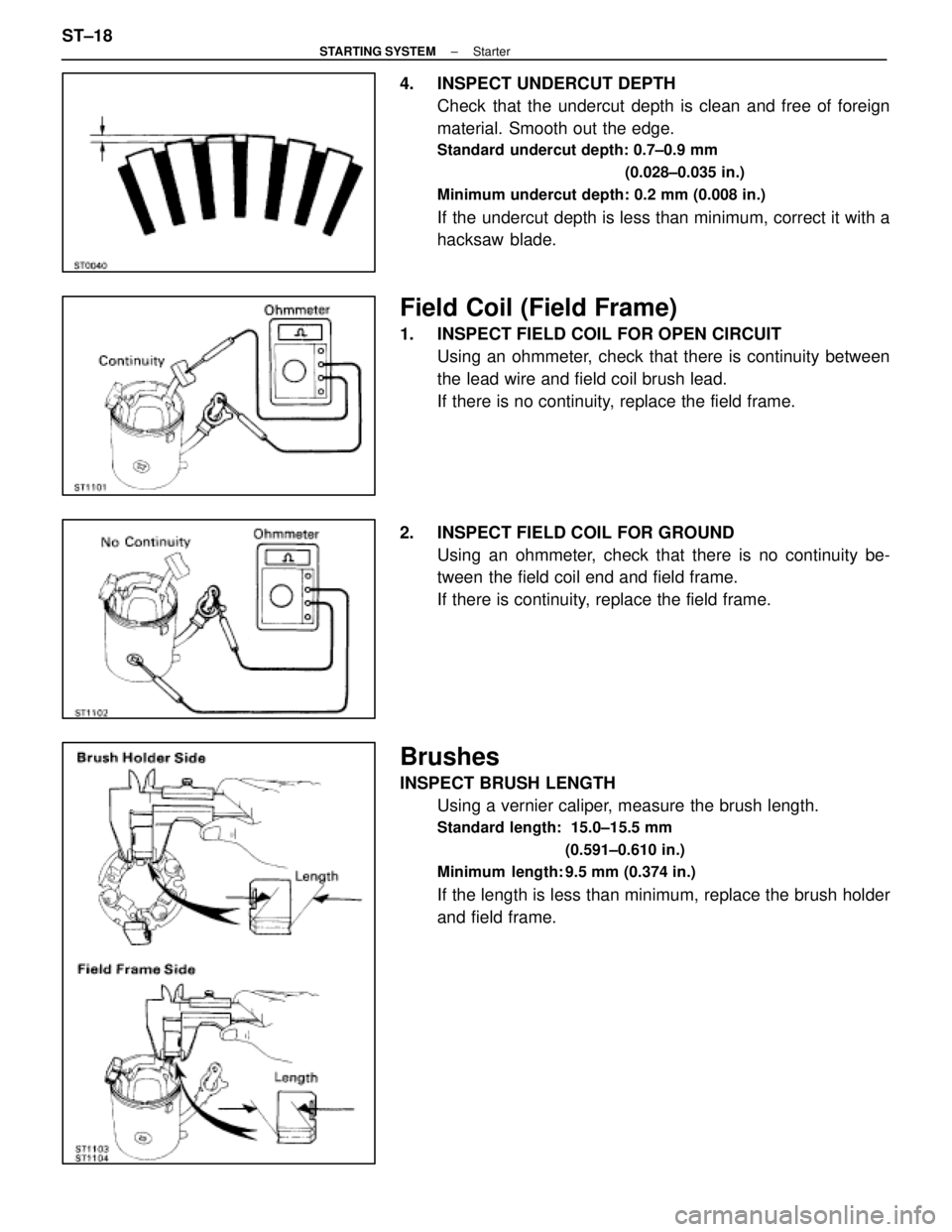
4. INSPECT UNDERCUT DEPTHCheck that the undercut depth is clean and free of foreign
material. Smooth out the edge.
Standard undercut depth: 0.7±0.9 mm
(0.028±0.035 in.)
Minimum undercut depth: 0.2 mm (0.008 in.)
If the undercut depth is less than minimum, correct it with a
hacksaw blade.
Field Coil (Field Frame)
1. INSPECT FIELD COIL FOR OPEN CIRCUIT Using an ohmmeter, check that there is continuity between
the lead wire and field coil brush lead.
If there is no continuity, replace the field frame.
2. INSPECT FIELD COIL FOR GROUND Using an ohmmeter, check that there is no continuity be-
tween the field coil end and field frame.
If there is continuity, replace the field frame.
Brushes
INSPECT BRUSH LENGTHUsing a vernier caliper, measure the brush length.
Standard length: 15.0±15.5 mm
(0.591±0.610 in.)
Minimum length: 9.5 mm (0.374 in.)
If the length is less than minimum, replace the brush holder
and field frame.
ST±18
±
STARTING SYSTEM Starter
WhereEverybodyKnowsYourName
Page 2911 of 4087
(b) Using SST and a press, press in a new bearing.SST 09201±41020
Magnetic Switch
1. PERFORM PULL±IN COIL OPEN CIRCUIT TESTUsing an ohmmeter, check that there is continuity between
terminals 50 and C.
If there is no continuity, replace the magnetic switch.
2. PERFORM HOLD±IN COIL OPEN CIRCUIT TEST Using an ohmmeter, check that there is continuity between
terminal 50 and the switch body.
If there is no continuity, replace the magnetic switch.
±
STARTING SYSTEM StarterST±21
WhereEverybodyKnowsYourName
Page 2914 of 4087
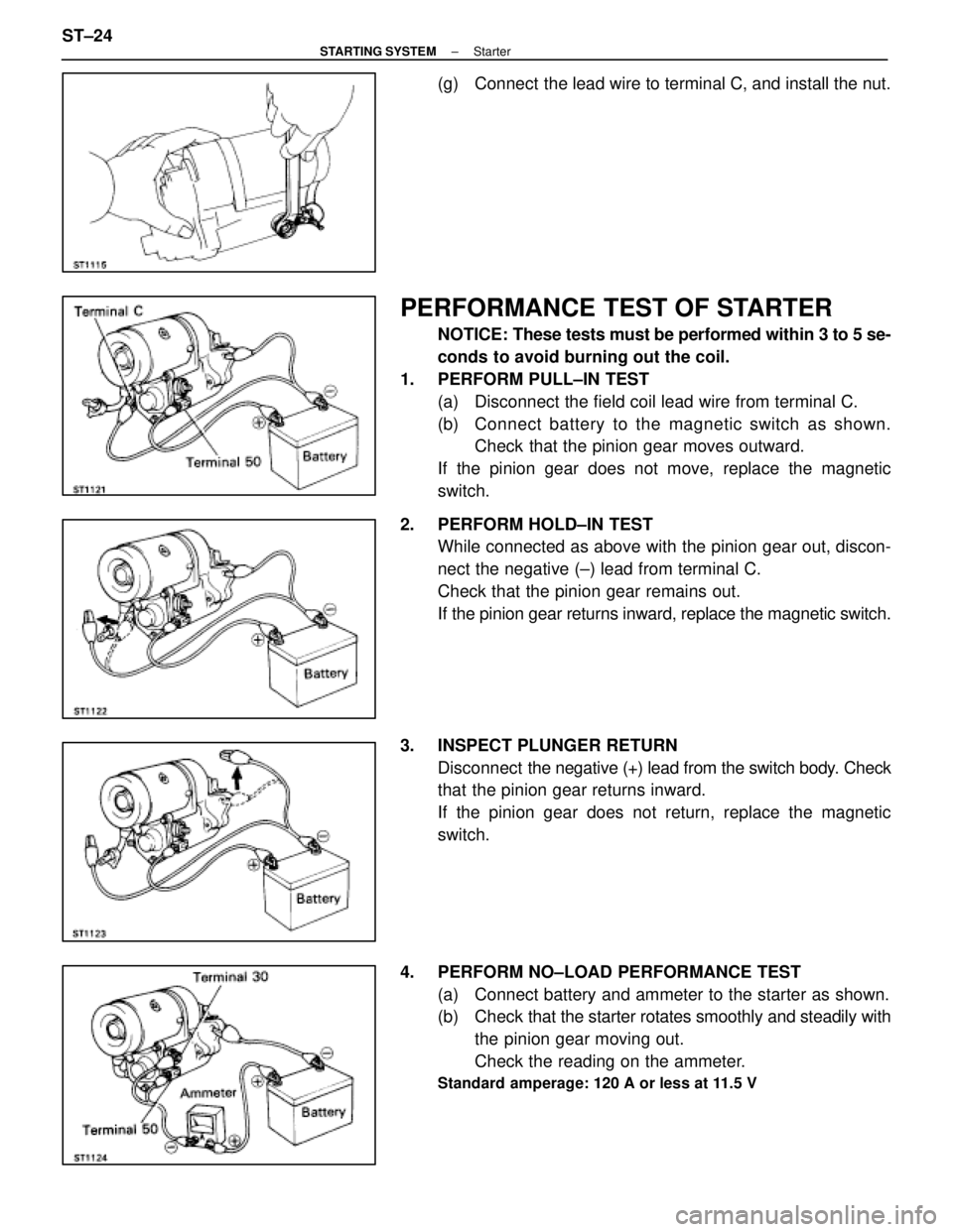
(g) Connect the lead wire to terminal C, and install the nut.
PERFORMANCE TEST OF STARTER
NOTICE: These tests must be performed within 3 to 5 se-
conds to avoid burning out the coil.
1. PERFORM PULL±IN TEST (a) Disconnect the field coil lead wire from terminal C.
(b) C onnect battery to the magnetic switch as shown.
Check that the pinion gear moves outward.
If the pinion gear does not move, replace the magnetic
switch.
2. PERFORM HOLD±IN TEST While connected as above with the pinion gear out, discon-
nect the negative (±) lead from terminal C.
Check that the pinion gear remains out.
If the pinion gear returns inward, replace the magnetic switch.
3. INSPECT PLUNGER RETURN Disconnect the negative (+) lead from the switch body. Check
that the pinion gear returns inward.
If the pinion gear does not return, replace the magnetic
switch.
4. PERFORM NO±LOAD PERFORMANCE TEST (a) Connect battery and ammeter to the starter as shown.
(b) Check that the starter rotates smoothly and steadily with
the pinion gear moving out.
Check the reading on the ammeter.
Standard amperage: 120 A or less at 11.5 V
ST±24±
STARTING SYSTEM Starter
WhereEverybodyKnowsYourName