Page 2562 of 4087
(d) Tighten the oil filter by hand until the rubber gasketcontacts the seat of the filter mounting. Then using SST,
give it an additional 3/4 turn to seat the oil filter.
SST 09228±07500
3. FILL WITH ENGINE OIL (a) Clean and install the oil drain plug with a new gasket.
Torque: 25 N Vm (250 kgf Vcm, 18 ft Vlbf)
(b) Fill with new engine oil.
Oil grade: See page LU±5
Capacity: Drain and refillw/ Oil filter change
4.8 liters (5.1 US qts, 4.2 lmp. qts)
w/o Oil filter change 4.5 liters (4.8 US qts, 4.0 lmp.qts)
Dry fill 6.0 liters (6.3 US qts, 5.3 lmp. qts)
(c) Reinstall the oil filler cap.
4. START ENGINE AND CHECK FOR LEAKS
5. RECHECK ENGINE OIL LEVEL (See page LU±5)
±
LUBRICATION SYSTEM Replacement of Engine Oil and Oil FilterLU±7
WhereEverybodyKnowsYourName
Page 2568 of 4087
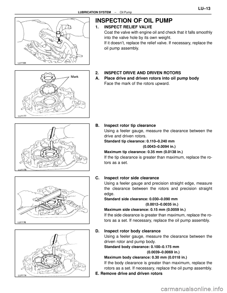
INSPECTION OF OIL PUMP
1. INSPECT RELIEF VALVECoat the valve with engine oil and check that it falls smoothly
into the valve hole by its own weight.
If it doesn't, replace the relief valve. If necessary, replace the
oil pump assembly.
2. INSPECT DRIVE AND DRIVEN ROTORS
A. Place drive and driven rotors into oil pump body Face the mark of the rotors upward.
B. Inspect rotor tip clearance Using a feeler gauge, measure the clearance between the
drive and driven rotors.
Standard tip clearance: 0.110±0.240 mm
(0.0043±0.0094 in.)
Maximum tip clearance: 0.35 mm (0.0138 in.)
If the tip clearance is greater than maximum, replace the ro-
tors as a set.
C. Inspect rotor side clearance Using a feeler gauge and precision straight edge, measure
the clearance between the rotors and precision straight
edge.
Standard side clearance: 0.030±0.090 mm
(0.0012±0.0035 in.)
Maximum side clearance: 0.15 mm (0.0059 in.)
If the side clearance is greater than maximum, replace the ro-
tors as a set. If necessary, replace the oil pump assembly.
D. Inspect rotor body clearance Using a feeler gauge, measure the clearance between the
driven rotor and pump body.
Standard body clearance: 0.100±0.175 mm
(0.0039±0.0069 in.)
Maximum body clearance: 0.30 mm (0.0118 in.)
If the body clearance is greater than maximum, replace the
rotors as a set. If necessary, replace the oil pump assembly.
E. Remove drive and driven rotors
±
LUBRICATION SYSTEM Oil PumpLU±13
WhereEverybodyKnowsYourName
Page 2592 of 4087
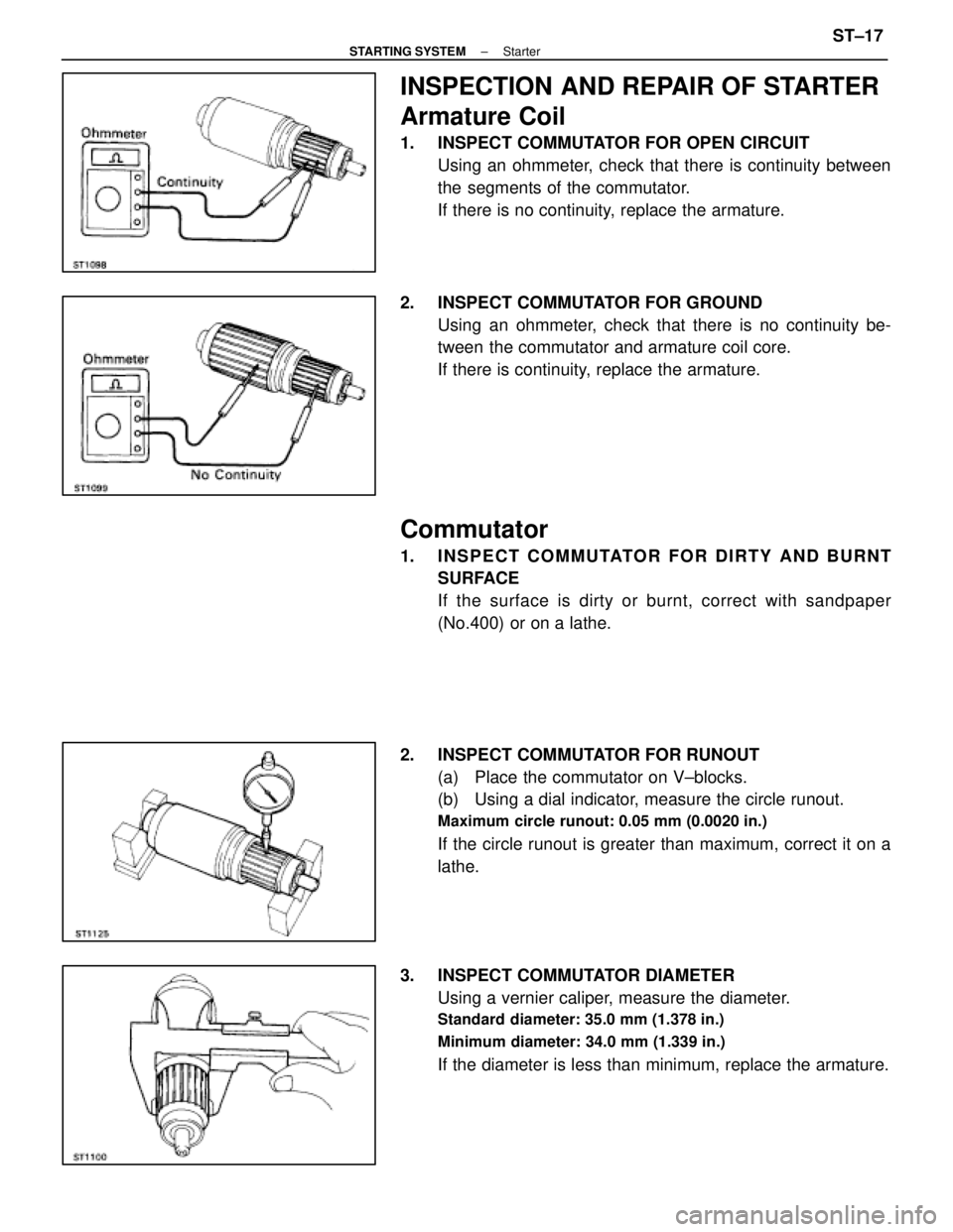
INSPECTION AND REPAIR OF STARTER
Armature Coil
1. INSPECT COMMUTATOR FOR OPEN CIRCUITUsing an ohmmeter, check that there is continuity between
the segments of the commutator.
If there is no continuity, replace the armature.
2. INSPECT COMMUTATOR FOR GROUND Using an ohmmeter, check that there is no continuity be-
tween the commutator and armature coil core.
If there is continuity, replace the armature.
Commutator
1. INSPECT COMMUTATOR FOR DIRTY AND BURNTSURFACE
If the surface is dirty or burnt, correct with sandpaper
(No.400) or on a lathe.
2. INSPECT COMMUTATOR FOR RUNOUT (a) Place the commutator on V±blocks.
(b) Using a dial indicator, measure the circle runout.
Maximum circle runout: 0.05 mm (0.0020 in.)
If the circle runout is greater than maximum, correct it on a
lathe.
3. INSPECT COMMUTATOR DIAMETER Using a vernier caliper, measure the diameter.
Standard diameter: 35.0 mm (1.378 in.)
Minimum diameter: 34.0 mm (1.339 in.)
If the diameter is less than minimum, replace the armature.
±
STARTING SYSTEM StarterST±17
WhereEverybodyKnowsYourName
Page 2593 of 4087
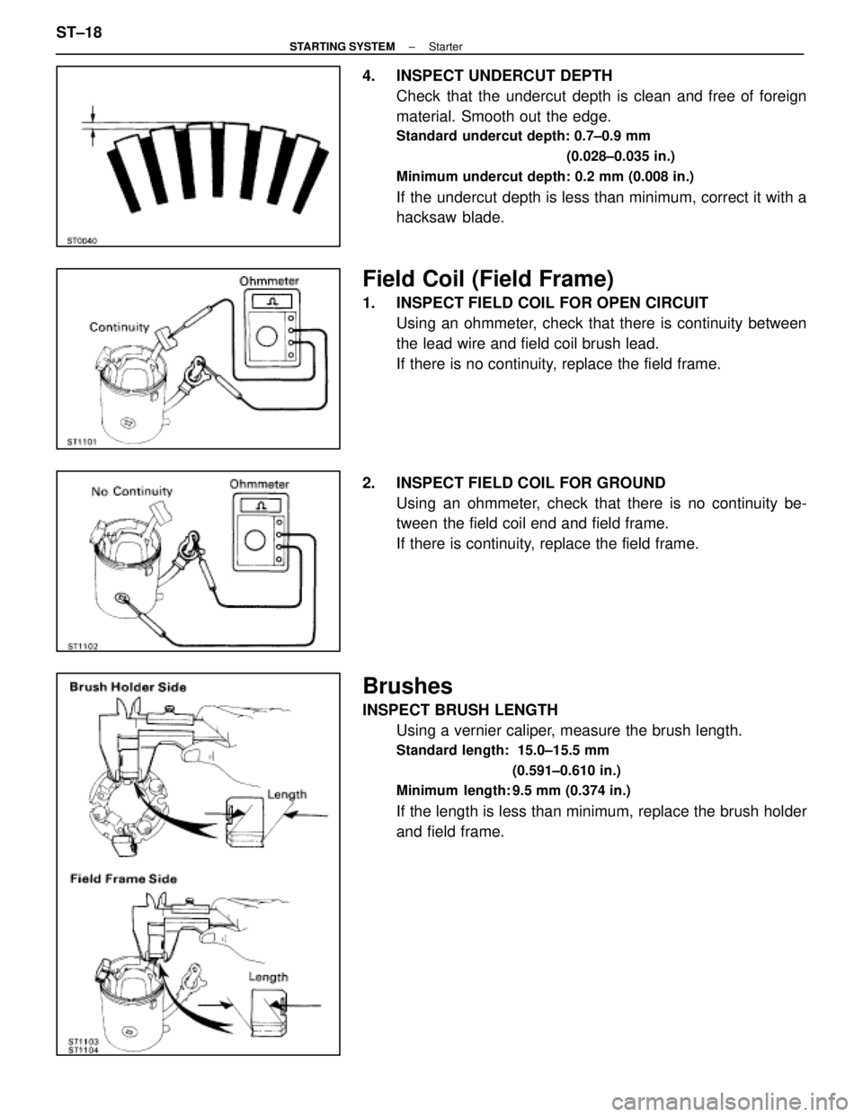
4. INSPECT UNDERCUT DEPTHCheck that the undercut depth is clean and free of foreign
material. Smooth out the edge.
Standard undercut depth: 0.7±0.9 mm
(0.028±0.035 in.)
Minimum undercut depth: 0.2 mm (0.008 in.)
If the undercut depth is less than minimum, correct it with a
hacksaw blade.
Field Coil (Field Frame)
1. INSPECT FIELD COIL FOR OPEN CIRCUIT Using an ohmmeter, check that there is continuity between
the lead wire and field coil brush lead.
If there is no continuity, replace the field frame.
2. INSPECT FIELD COIL FOR GROUND Using an ohmmeter, check that there is no continuity be-
tween the field coil end and field frame.
If there is continuity, replace the field frame.
Brushes
INSPECT BRUSH LENGTHUsing a vernier caliper, measure the brush length.
Standard length: 15.0±15.5 mm
(0.591±0.610 in.)
Minimum length: 9.5 mm (0.374 in.)
If the length is less than minimum, replace the brush holder
and field frame.
ST±18
±
STARTING SYSTEM Starter
WhereEverybodyKnowsYourName
Page 2596 of 4087
(b) Using SST and a press, press in a new bearing.SST 09201±41020
Magnetic Switch
1. PERFORM PULL±IN COIL OPEN CIRCUIT TESTUsing an ohmmeter, check that there is continuity between
terminals 50 and C.
If there is no continuity, replace the magnetic switch.
2. PERFORM HOLD±IN COIL OPEN CIRCUIT TEST Using an ohmmeter, check that there is continuity between
terminal 50 and the switch body.
If there is no continuity, replace the magnetic switch.
±
STARTING SYSTEM StarterST±21
WhereEverybodyKnowsYourName
Page 2599 of 4087
(g) Connect the lead wire to terminal C, and install the nut.
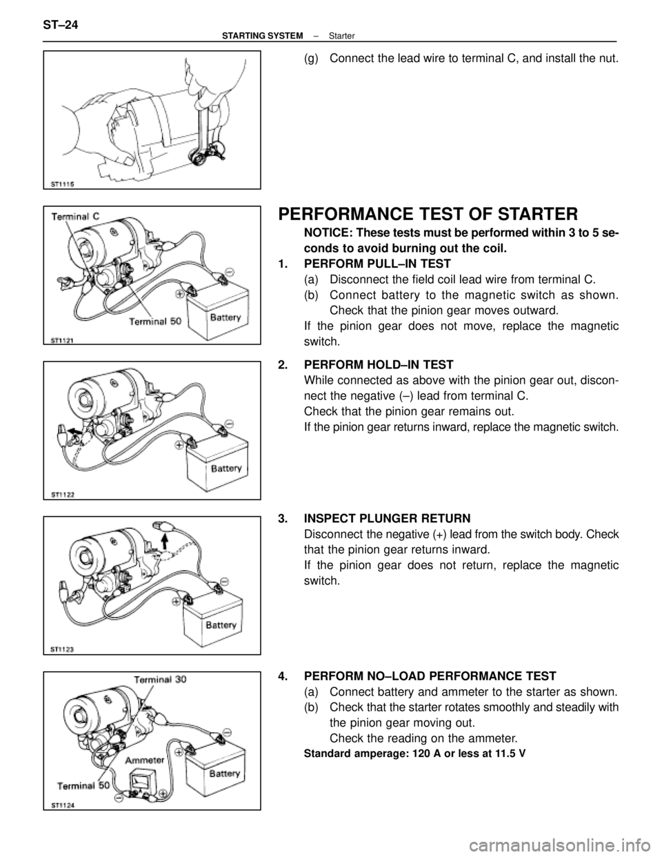
PERFORMANCE TEST OF STARTER
NOTICE: These tests must be performed within 3 to 5 se-
conds to avoid burning out the coil.
1. PERFORM PULL±IN TEST (a) Disconnect the field coil lead wire from terminal C.
(b) C onnect battery to the magnetic switch as shown.
Check that the pinion gear moves outward.
If the pinion gear does not move, replace the magnetic
switch.
2. PERFORM HOLD±IN TEST While connected as above with the pinion gear out, discon-
nect the negative (±) lead from terminal C.
Check that the pinion gear remains out.
If the pinion gear returns inward, replace the magnetic switch.
3. INSPECT PLUNGER RETURN Disconnect the negative (+) lead from the switch body. Check
that the pinion gear returns inward.
If the pinion gear does not return, replace the magnetic
switch.
4. PERFORM NO±LOAD PERFORMANCE TEST (a) Connect battery and ammeter to the starter as shown.
(b) Check that the starter rotates smoothly and steadily with
the pinion gear moving out.
Check the reading on the ammeter.
Standard amperage: 120 A or less at 11.5 V
ST±24±
STARTING SYSTEM Starter
WhereEverybodyKnowsYourName
Page 2635 of 4087
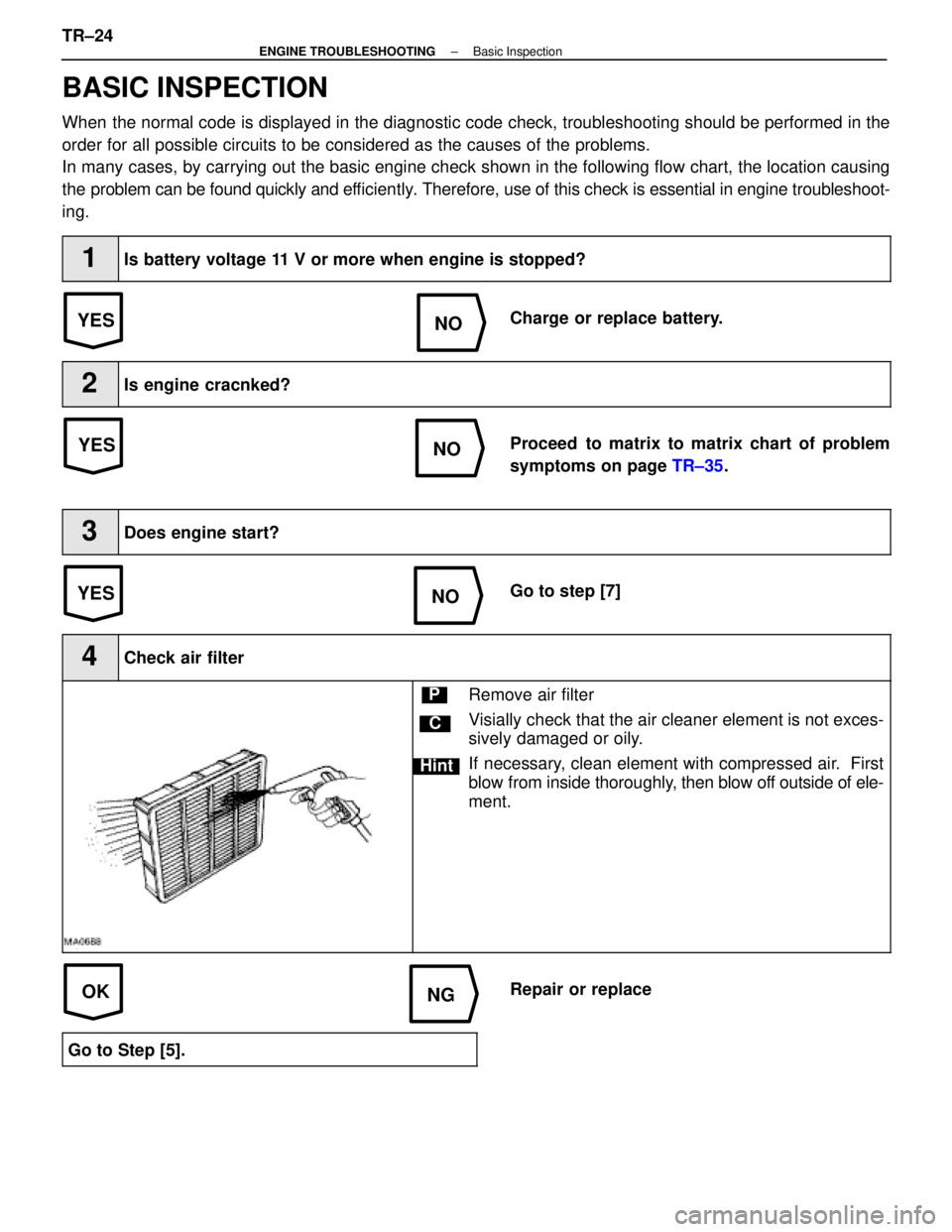
YESNO
NOYES
YES
NO
OKNG
BASIC INSPECTION
When the normal code is displayed in the diagnostic code check, troubleshoot\
ing should be performed in the
order for all possible circuits to be considered as the causes of the pr\
oblems.
In many cases, by carrying out the basic engine check shown in the follo\
wing flow chart, the location causing
the problem can be found quickly and ef ficiently. Therefore, use of this check is essential in engine troubleshoot-
ing.
1Is battery voltage 11 V or more when engine is stopped?
Charge or replace battery.
2Is engine cracnked?
Proceed to matrix to matrix chart of problem
symptoms on page TR±35.
3Does engine start?
Go to step [7]
4Check air filter
C
Hint
PRemove air filter
Visially check that the air cleaner element is not exces-
sively damaged or oily.
If necessary, clean element with compressed air. First
blow from inside thoroughly, then blow off outside of ele-
ment.
Repair or replace
Go to Step [5].
TR±24±
ENGINE TROUBLESHOOTING Basic Inspection
WhereEverybodyKnowsYourName
Page 2636 of 4087
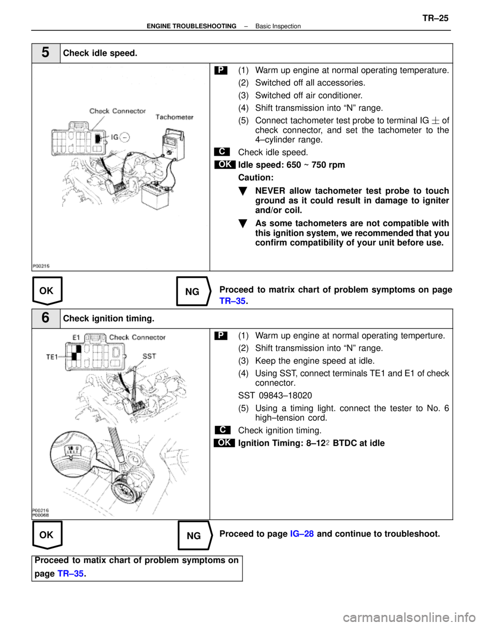
OKNG
OKNG
5Check idle speed.
C
OK
P(1) Warm up engine at normal operating temperature.
(2) Switched off all accessories.
(3) Switched off air conditioner.
(4) Shift transmission into ªNº range.
(5) Connect tachometer test probe to terminal IG � of
check connector, and set the tachometer to the
4±cylinder range.
Check idle speed.
Idle speed: 650 ~ 750 rpm
Caution:
�NEVER allow tachometer test probe to touch
ground as it could result in damage to igniter
and/or coil.
�As some tachometers are not compatible with
this ignition system, we recommended that you
confirm compatibility of your unit before use.
Proceed to matrix chart of problem symptoms on page
TR±35 .
6Check ignition timing.
C
OK
P(1) Warm up engine at normal operating temperture.
(2) Shift transmission into ªNº range.
(3) Keep the engine speed at idle.
(4) Using SST, connect terminals TE1 and E1 of check
connector.
SST 09843±18020
(5) Using a timing light. connect the tester to No. 6 high±tension cord.
Check ignition timing.
Ignition Timing: 8±12 � BTDC at idle
Proceed to page IG±28 and continue to troubleshoot.
Proceed to matix chart of problem symptoms on
page TR±35 .
±
ENGINE TROUBLESHOOTING Basic InspectionTR±25
WhereEverybodyKnowsYourName