Page 2293 of 4087
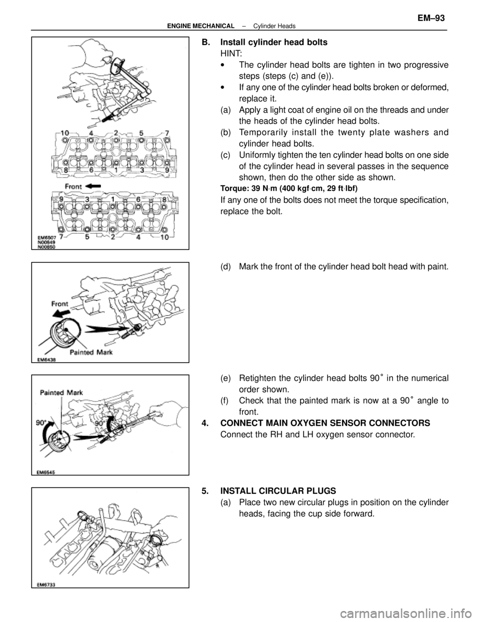
B. Install cylinder head boltsHINT:
wThe cylinder head bolts are tighten in two progressive
steps (steps (c) and (e)).
w If any one of the cylinder head bolts broken or deformed,
replace it.
(a) Apply a light coat of engine oil on the threads and under
the heads of the cylinder head bolts.
(b) Te mp o ra rily in sta ll th e twe n ty pla te wa sh e rs an d cylinder head bolts.
(c) Uniformly tighten the ten cylinder head bolts on one side
of the cylinder head in several passes in the sequence
shown, then do the other side as shown.
Torque: 39 N Vm (400 kgf Vcm, 29 ft Vlbf)
If any one of the bolts does not meet the torque specification,
replace the bolt.
(d) Mark the front of the cylinder head bolt head with paint.
(e) Retighten the cylinder head bolts 90 ° in the numerical
order shown.
(f) Check that the painted mark is now at a 90 ° angle to
front.
4. CONNECT MAIN OXYGEN SENSOR CONNECTORS Connect the RH and LH oxygen sensor connector.
5. INSTALL CIRCULAR PLUGS (a) Place two new circular plugs in position on the cylinderheads, facing the cup side forward.
±
ENGINE MECHANICAL Cylinder HeadsEM±93
WhereEverybodyKnowsYourName
Page 2297 of 4087
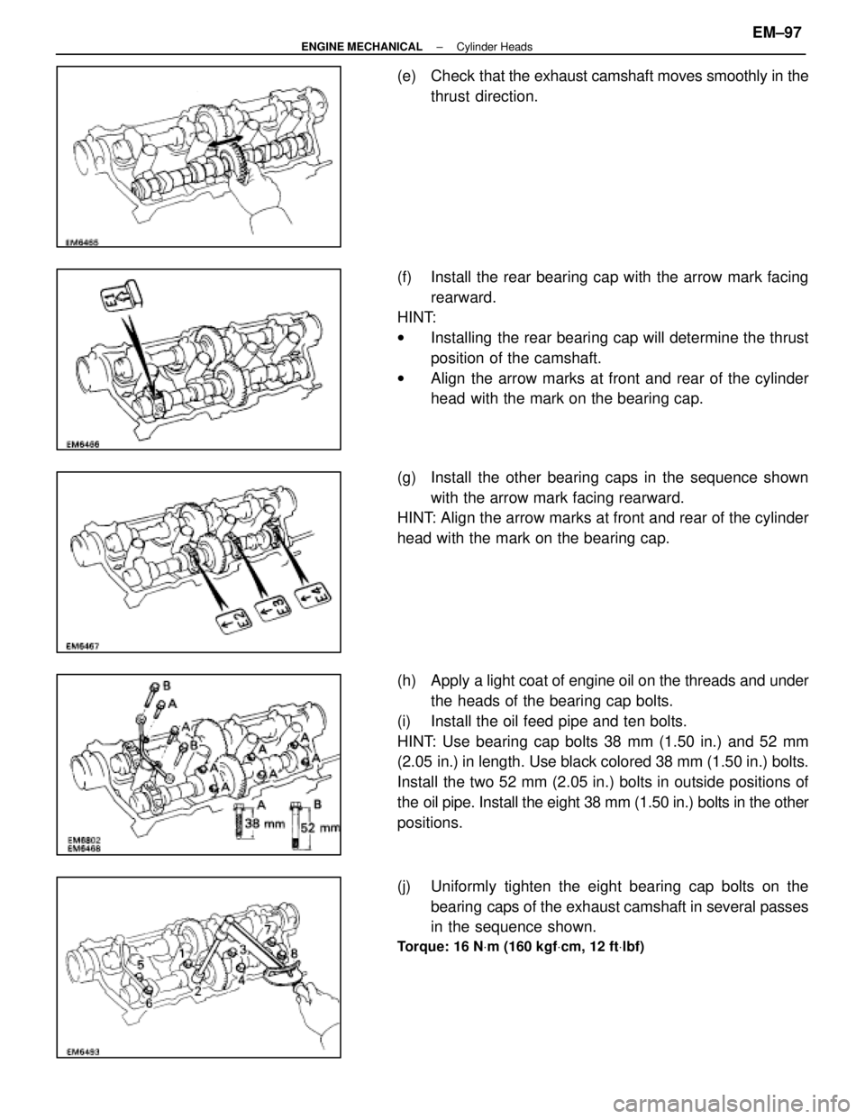
(e) Check that the exhaust camshaft moves smoothly in the
thrust direction.
(f) Install the rear bearing cap with the arrow mark facing rearward.
HINT:
w Installing the rear bearing cap will determine the thrust
position of the camshaft.
w Align the arrow marks at front and rear of the cylinder
head with the mark on the bearing cap.
(g) Install the other bearing caps in the sequence shown with the arrow mark facing rearward.
HINT: Align the arrow marks at front and rear of the cylinder
head with the mark on the bearing cap.
(h) Apply a light coat of engine oil on the threads and under
the heads of the bearing cap bolts.
(i) Install the oil feed pipe and ten bolts.
HINT: Use bearing cap bolts 38 mm (1.50 in.) and 52 mm
(2.05 in.) in length. Use black colored 38 mm (1.50 in.) bolts.
Install the two 52 mm (2.05 in.) bolts in outside positions of
the oil pipe. Install the eight 38 mm (1.50 in.) bolts in the other
positions.
(j) Uniformly tighten the eight bearing cap bolts on the bearing caps of the exhaust camshaft in several passes
in the sequence shown.
Torque: 16 N Vm (160 kgf Vcm, 12 ft Vlbf)
±
ENGINE MECHANICAL Cylinder HeadsEM±97
WhereEverybodyKnowsYourName
Page 2300 of 4087
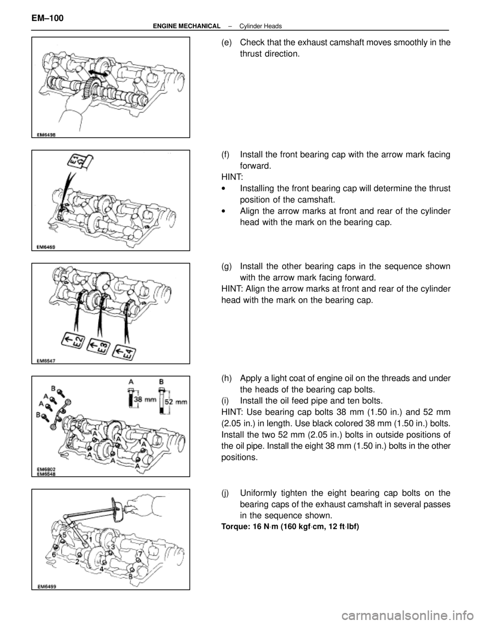
(e) Check that the exhaust camshaft moves smoothly in the
thrust direction.
(f) Install the front bearing cap with the arrow mark facing forward.
HINT:
w Installing the front bearing cap will determine the thrust
position of the camshaft.
w Align the arrow marks at front and rear of the cylinder
head with the mark on the bearing cap.
(g) Install the other bearing caps in the sequence shown with the arrow mark facing forward.
HINT: Align the arrow marks at front and rear of the cylinder
head with the mark on the bearing cap.
(h) Apply a light coat of engine oil on the threads and under
the heads of the bearing cap bolts.
(i) Install the oil feed pipe and ten bolts.
HINT: Use bearing cap bolts 38 mm (1.50 in.) and 52 mm
(2.05 in.) in length. Use black colored 38 mm (1.50 in.) bolts.
Install the two 52 mm (2.05 in.) bolts in outside positions of
the oil pipe. Install the eight 38 mm (1.50 in.) bolts in the other
positions.
(j) Uniformly tighten the eight bearing cap bolts on the
bearing caps of the exhaust camshaft in several passes
in the sequence shown.
Torque: 16 N Vm (160 kgf Vcm, 12 ft Vlbf)
EM±100±
ENGINE MECHANICAL Cylinder Heads
WhereEverybodyKnowsYourName
Page 2301 of 4087
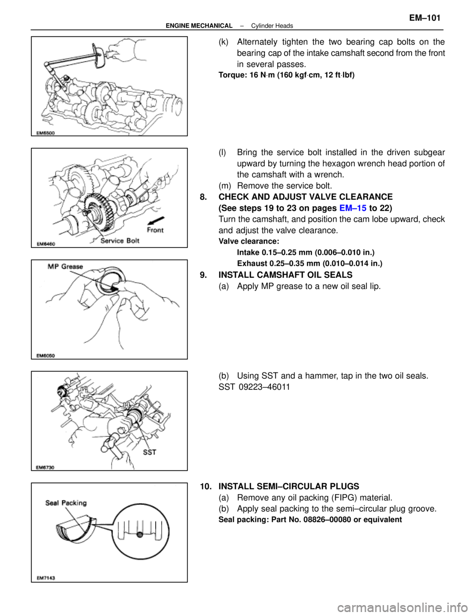
(k) Alternately tighten the two bearing cap bolts on thebearing cap of the intake camshaft second from the front
in several passes.
Torque: 16 N Vm (160 kgf Vcm, 12 ft Vlbf)
(l) Bring the service bolt installed in the driven subgear
upward by turning the hexagon wrench head portion of
the camshaft with a wrench.
(m) Remove the service bolt.
8. CHECK AND ADJUST VALVE CLEARANCE (See steps 19 to 23 on pages EM±15 to 22)
Turn the camshaft, and position the cam lobe upward, check
and adjust the valve clearance.
Valve clearance:
Intake 0.15±0.25 mm (0.006±0.010 in.)
Exhaust 0.25±0.35 mm (0.010±0.014 in.)
9. INSTALL CAMSHAFT OIL SEALS(a) Apply MP grease to a new oil seal lip.
(b) Using SST and a hammer, tap in the two oil seals.
SST 09223±46011
10. INSTALL SEMI±CIRCULAR PLUGS (a) Remove any oil packing (FIPG) material.
(b) Apply seal packing to the semi±circular plug groove.
Seal packing: Part No. 08826±00080 or equivalent
±
ENGINE MECHANICAL Cylinder HeadsEM±101
WhereEverybodyKnowsYourName
Page 2335 of 4087
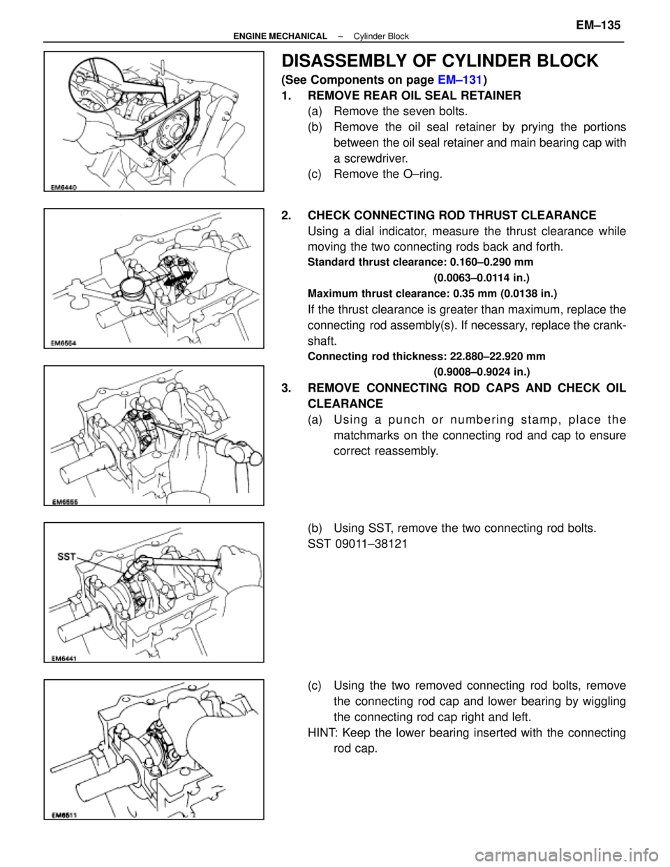
DISASSEMBLY OF CYLINDER BLOCK
(See Components on page EM±131)
1. REMOVE REAR OIL SEAL RETAINER (a) Remove the seven bolts.
(b) Remove the oil seal retainer by prying the portions
between the oil seal retainer and main bearing cap with
a screwdriver.
(c) Remove the O±ring.
2. CHECK CONNECTING ROD THRUST CLEARANCE Using a dial indicator, measure the thrust clearance while
moving the two connecting rods back and forth.
Standard thrust clearance: 0.160±0.290 mm
(0.0063±0.0114 in.)
Maximum thrust clearance: 0.35 mm (0.0138 in.)
If the thrust clearance is greater than maximum, replace the
connecting rod assembly(s). If necessary, replace the crank-
shaft.
Connecting rod thickness: 22.880±22.920 mm (0.9008±0.9024 in.)
3. REMOVE CONNECTING ROD CAPS AND CHECK OILCLEARANCE
(a) Using a punch or numbering stamp, place thematchmarks on the connecting rod and cap to ensure
correct reassembly.
(b) Using SST, remove the two connecting rod bolts.
SST 09011±38121
(c) Using the two removed connecting rod bolts, remove the connecting rod cap and lower bearing by wiggling
the connecting rod cap right and left.
HINT: Keep the lower bearing inserted with the connecting rod cap.
±
ENGINE MECHANICAL Cylinder BlockEM±135
WhereEverybodyKnowsYourName
Page 2338 of 4087
HINT:
wKeep the bearings, connecting rod and cap together.
w Arrange the piston and connecting rod assemblies in
correct order.
5. CHECK CRANKSHAFT THRUST CLEARANCE Using a dial indi cator, measure the thrust clearance while pry-
ing the crankshaft back and forth with a screwdriver.
Standard thrust clearance: 0.020±0.220 mm
(0.0008±0.0087 in.)
Maximum thrust clearance: 0.30 mm (0.0118 in.)
If the thrust clearance is greater than maximum, replace the
thrust washers as a set.
Thrust washer thickness: 2.440±2.490 mm (0.0961±0.0980 in.)
6. REMOVE MAIN BEARING CAP AND CHECK OILCLEARANCE
(a) Remove the ten main bearing cap bolts.
(b) Uniformly loosen and remove the twenty main bearingcap nuts in several passes in the sequence shown.
EM±138
±
ENGINE MECHANICAL Cylinder Block
WhereEverybodyKnowsYourName
Page 2344 of 4087
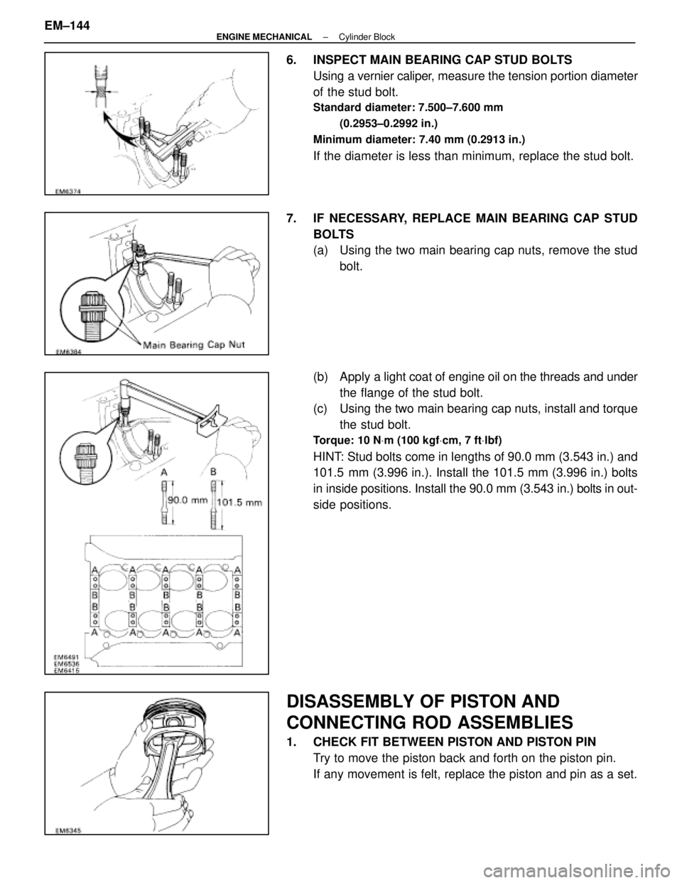
6. INSPECT MAIN BEARING CAP STUD BOLTSUsing a vernier caliper, measure the tension portion diameter
of the stud bolt.
Standard diameter: 7.500±7.600 mm
(0.2953±0.2992 in.)
Minimum diameter: 7.40 mm (0.2913 in.)
If the diameter is less than minimum, replace the stud bolt.
7. IF NECESSARY, REPLACE MAIN BEARING CAP STUD BOLTS
(a) Using the two main bearing cap nuts, remove the studbolt.
(b) Apply a light coat of engine oil on the threads and under
the flange of the stud bolt.
(c) Using the two main bearing cap nuts, install and torque
the stud bolt.
Torque: 10 N Vm (100 kgf Vcm, 7 ft Vlbf)
HINT: Stud bolts come in lengths of 90.0 mm (3.543 in.) and
101.5 mm (3.996 in.). Install the 101.5 mm (3.996 in.) bolts
in inside positions. Install the 90.0 mm (3.543 in.) bolts in out-
side positions.
DISASSEMBLY OF PISTON AND
CONNECTING ROD ASSEMBLIES
1. CHECK FIT BETWEEN PISTON AND PISTON PIN
Try to move the piston back and forth on the piston pin.
If any movement is felt, replace the piston and pin as a set.
EM±144
±
ENGINE MECHANICAL Cylinder Block
WhereEverybodyKnowsYourName
Page 2349 of 4087
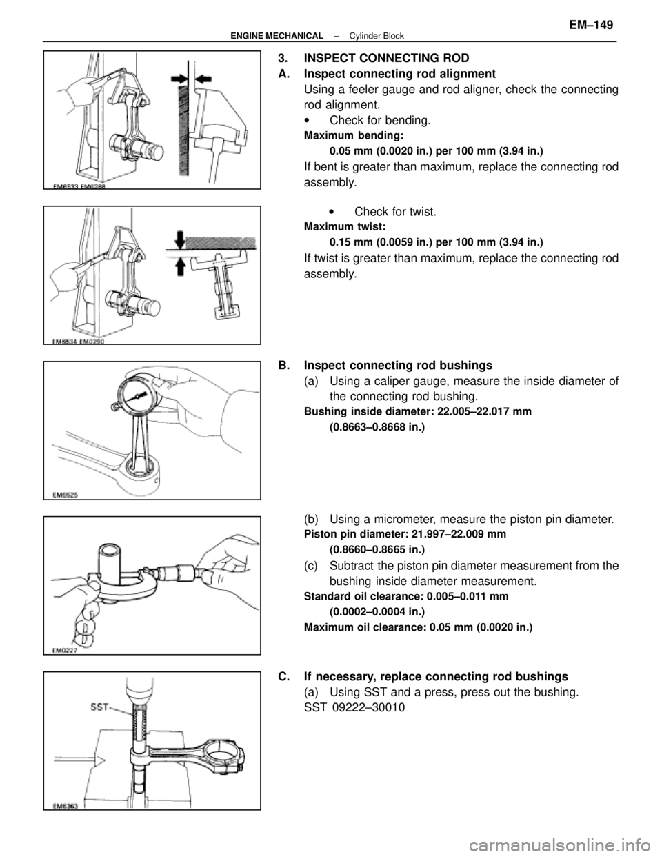
3. INSPECT CONNECTING ROD
A. Inspect connecting rod alignmentUsing a feeler gauge and rod aligner, check the connecting
rod alignment.
wCheck for bending.
Maximum bending:
0.05 mm (0.0020 in.) per 100 mm (3.94 in.)
If bent is greater than maximum, replace the connecting rod
assembly.
w Check for twist.
Maximum twist:
0.15 mm (0.0059 in.) per 100 mm (3.94 in.)
If twist is greater than maximum, replace the connecting rod
assembly.
B. Inspect connecting rod bushings (a) Using a caliper gauge, measure the inside diameter ofthe connecting rod bushing.
Bushing inside diameter: 22.005±22.017 mm
(0.8663±0.8668 in.)
(b) Using a micrometer, measure the piston pin diameter.
Piston pin diameter: 21.997±22.009 mm(0.8660±0.8665 in.)
(c) Subtract the piston pin diameter measurement from thebushing inside diameter measurement.
Standard oil clearance: 0.005±0.011 mm
(0.0002±0.0004 in.)
Maximum oil clearance: 0.05 mm (0.0020 in.)
C. If necessary, replace connecting rod bushings (a) Using SST and a press, press out the bushing.
SST 09222±30010
±
ENGINE MECHANICAL Cylinder BlockEM±149
WhereEverybodyKnowsYourName