Page 559 of 4087

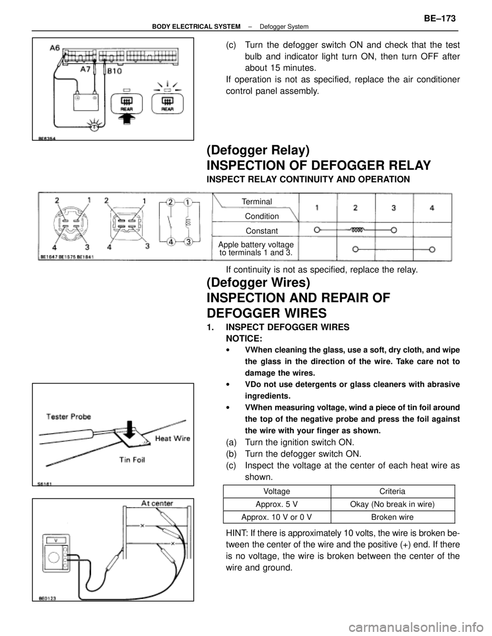
(c) Turn the defogger switch ON and check that the testbulb and indicator light turn ON, then turn OFF after
about 15 minutes.
If operation is not as specified, replace the air conditioner
control panel assembly.
(Defogger Relay)
INSPECTION OF DEFOGGER RELAY
INSPECT RELAY CONTINUITY AND OPERATION
Terminal
ConditionConstant
Apple battery voltage to terminals 1 and 3.
If continuity is not as specified, replace the relay.
(Defogger Wires)
INSPECTION AND REPAIR OF
DEFOGGER WIRES
1. INSPECT DEFOGGER WIRES
NOTICE:
w VWhen cleaning the glass, use a soft, dry cloth, and wipe
the glass in the direction of the wire. Take care not to
damage the wires.
w VDo not use detergents or glass cleaners with abrasive
ingredients.
w VWhen measuring voltage, wind a piece of tin foil around
the top of the negative probe and press the foil against
the wire with your finger as shown.
(a) Turn the ignition switch ON.
(b) Turn the defogger switch ON.
(c) Inspect the voltage at the center of each heat wire as
shown.
VoltageCriteria
Approx. 5 VOkay (No break in wire)
Approx. 10 V or 0 VBroken wire
HINT: If there is approximately 10 volts, the wire is broken be-
tween the center of the wire and the positive (+) end. If there
is no voltage, the wire is broken between the center of the
wire and ground.
±
BODY ELECTRICAL SYSTEM Defogger SystemBE±173
WhereEverybodyKnowsYourName
Page 849 of 4087

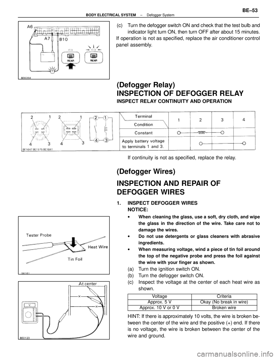
(c) Turn the defogger switch ON and check that the test bulb andindicator light turn ON, then turn OFF after about 15 minutes.
If operation is not as specified, replace the air conditioner control
panel assembly.
(Defogger Relay)
INSPECTION OF DEFOGGER RELAY
INSPECT RELAY CONTINUITY AND OPERATION
If continuity is not as specified, replace the relay.
(Defogger Wires)
INSPECTION AND REPAIR OF
DEFOGGER WIRES
1. INSPECT DEFOGGER WIRESNOTICE:
w When cleaning the glass, use a soft, dry cloth, and wipe
the glass in the direction of the wire. Take care not to
damage the wires.
w Do not use detergents or glass cleaners with abrasive
ingredients.
w When measuring voltage, wind a piece of tin foil around
the top of the negative probe and press the foil against
the wire with your finger as shown.
(a) Turn the ignition switch ON.
(b) Turn the defogger switch ON.
(c) Inspect the voltage at the center of each heat wire as
shown.
���������� ����������Voltage���������� ����������Criteria
����������Approx. 5 V����������Okay (No break in wire)���������� ����������Approx. 10 V or 0 V���������� ����������Broken wire
HINT: If there is approximately 10 volts, the wire is broken be-
tween the center of the wire and the positive (+) end. If there
is no voltage, the wire is broken between the center of the
wire and ground.
±
BODY ELECTRICAL SYSTEM Defogger SystemBE±53
WhereEverybodyKnowsYourName
Page 852 of 4087

(TAILLIGHT SYSTEM)
Description ± Taillight System
The component parts of this system and their function are as shown in the f\
ollowing table.
�������� ��������Parts Name������������������\
����������� ������������������\
�����������Function
�������� �
�������
��������
Light Control Switch������������������\
����������� �
������������������\
����������
������������������\
�����������
Grounds current from the taillight control relay via the integration rel\
ay, switching each relay
and supplying current to the appropriate bulbs accordance with the switc\
h position.
�������� ��������Taillight Control Relay������������������\
����������� ������������������\
�����������Turned on by signals from the light control switch and supplies current t\
o each bulb.
�������� �
�������
�
�������
��������
Integration Relay
������������������\
����������� �
������������������\
����������
�
������������������\
����������
������������������\
�����������
Carries out ºLight Auto Turn±Offº of the headlights, fog lights and taillights and cuts off cur-
rent to the light control switch in accordance with signals from the GAU\
GE fuse and door
courtesy switch.
�������� �
�������
��������
Light Failure Sensor������������������\
����������� �
������������������\
����������
������������������\
�����������
This sensor senses when a bulb in rear combination light is burnt out an\
d lights up a warning
light.
��������Integration Relay������������������\
������������������� ��������Integration Relay
(Daytime Running
������������������\
����������� ������������������\
�����������
Refer to
BE±30.�������� ��������(y g
Light Relay: CANADA)������������������\
����������� ������������������\
�����������
PARTS LOCATION ± Taillight System
±
BODY ELECTRICAL SYSTEM Lighting SystemBE±53
WhereEverybodyKnowsYourName
Page 2761 of 4087

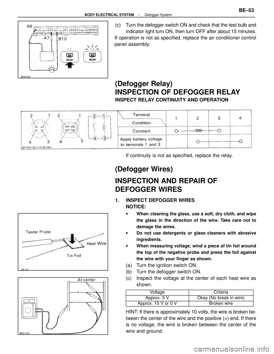
(c) Turn the defogger switch ON and check that the test bulb andindicator light turn ON, then turn OFF after about 15 minutes.
If operation is not as specified, replace the air conditioner control
panel assembly.
(Defogger Relay)
INSPECTION OF DEFOGGER RELAY
INSPECT RELAY CONTINUITY AND OPERATION
If continuity is not as specified, replace the relay.
(Defogger Wires)
INSPECTION AND REPAIR OF
DEFOGGER WIRES
1. INSPECT DEFOGGER WIRESNOTICE:
w When cleaning the glass, use a soft, dry cloth, and wipe
the glass in the direction of the wire. Take care not to
damage the wires.
w Do not use detergents or glass cleaners with abrasive
ingredients.
w When measuring voltage, wind a piece of tin foil around
the top of the negative probe and press the foil against
the wire with your finger as shown.
(a) Turn the ignition switch ON.
(b) Turn the defogger switch ON.
(c) Inspect the voltage at the center of each heat wire as
shown.
���������� ����������Voltage���������� ����������Criteria
����������Approx. 5 V����������Okay (No break in wire)���������� ����������Approx. 10 V or 0 V���������� ����������Broken wire
HINT: If there is approximately 10 volts, the wire is broken be-
tween the center of the wire and the positive (+) end. If there
is no voltage, the wire is broken between the center of the
wire and ground.
±
BODY ELECTRICAL SYSTEM Defogger SystemBE±53
WhereEverybodyKnowsYourName