Page 1435 of 4087
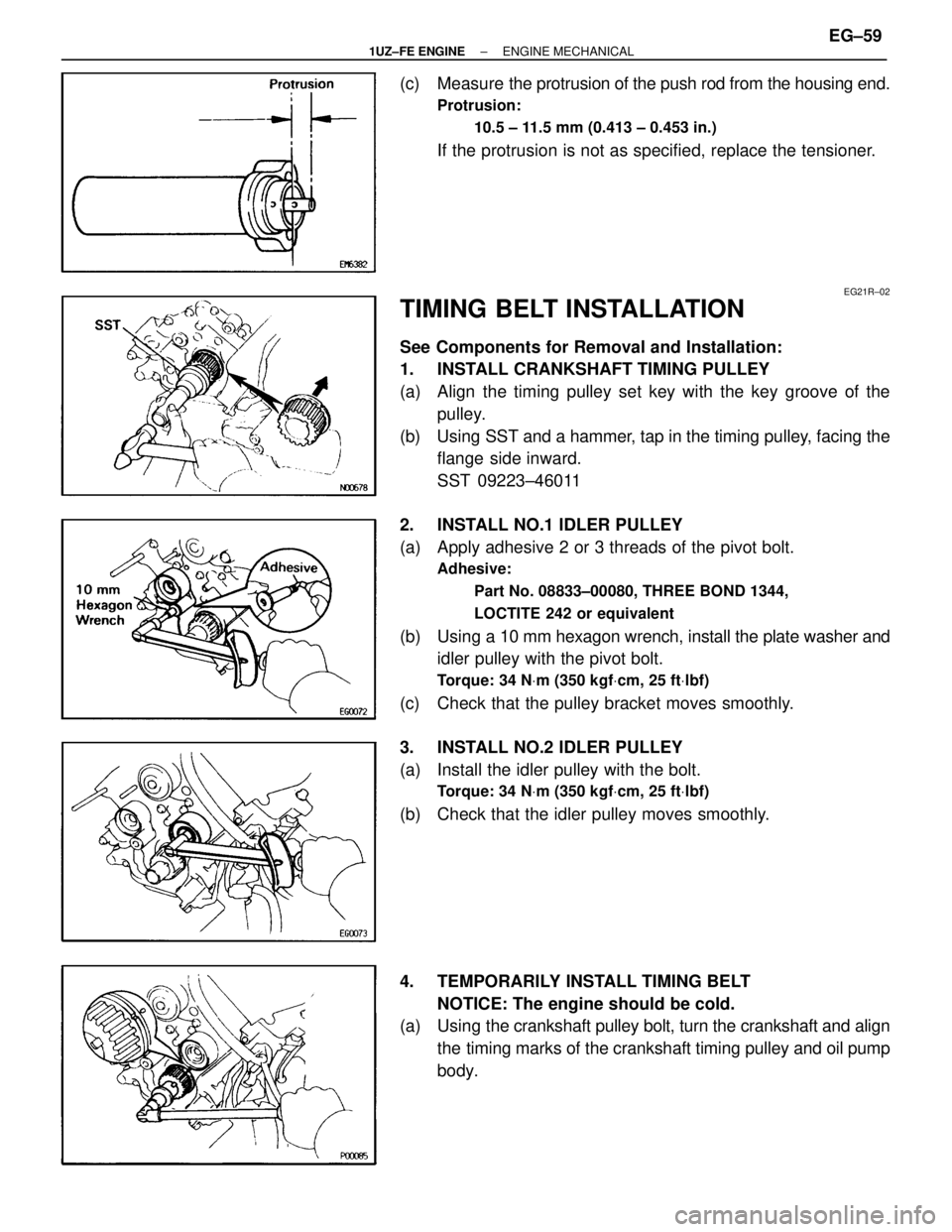
(c) Measure the protrusion of the push rod from the housing end.
Protrusion:
10.5 ± 11.5 mm (0.413 ± 0.453 in.)
If the protrusion is not as specified, replace the tensioner.
EG21R±02
TIMING BELT INSTALLATION
See Components for Removal and Installation:
1. INSTALL CRANKSHAFT TIMING PULLEY
(a) Align the timing pulley set key with the key groove of thepulley.
(b) Using SST and a hammer, tap in the timing pulley, facing the flange side inward.
SST 09223±46011
2. INSTALL NO.1 IDLER PULLEY
(a) Apply adhesive 2 or 3 threads of the pivot bolt.
Adhesive: Part No. 08833±00080, THREE BOND 1344,
LOCTITE 242 or equivalent
(b) Using a 10 mm hexagon wrench, install the plate washer and
idler pulley with the pivot bolt.
Torque: 34 N Vm (350 kgf Vcm, 25 ft Vlbf)
(c) Check that the pulley bracket moves smoothly.
3. INSTALL NO.2 IDLER PULLEY
(a) Install the idler pulley with the bolt.
Torque: 34 N Vm (350 kgf Vcm, 25 ft Vlbf)
(b) Check that the idler pulley moves smoothly.
4. TEMPORARILY INSTALL TIMING BELT
NOTICE: The engine should be cold.
(a) Using the crankshaft pulley bolt, turn the crankshaft and align
the timing marks of the crankshaft timing pulley and oil pump
body.
±
1UZ±FE ENGINE ENGINE MECHANICALEG±59
WhereEverybodyKnowsYourName
Page 1439 of 4087
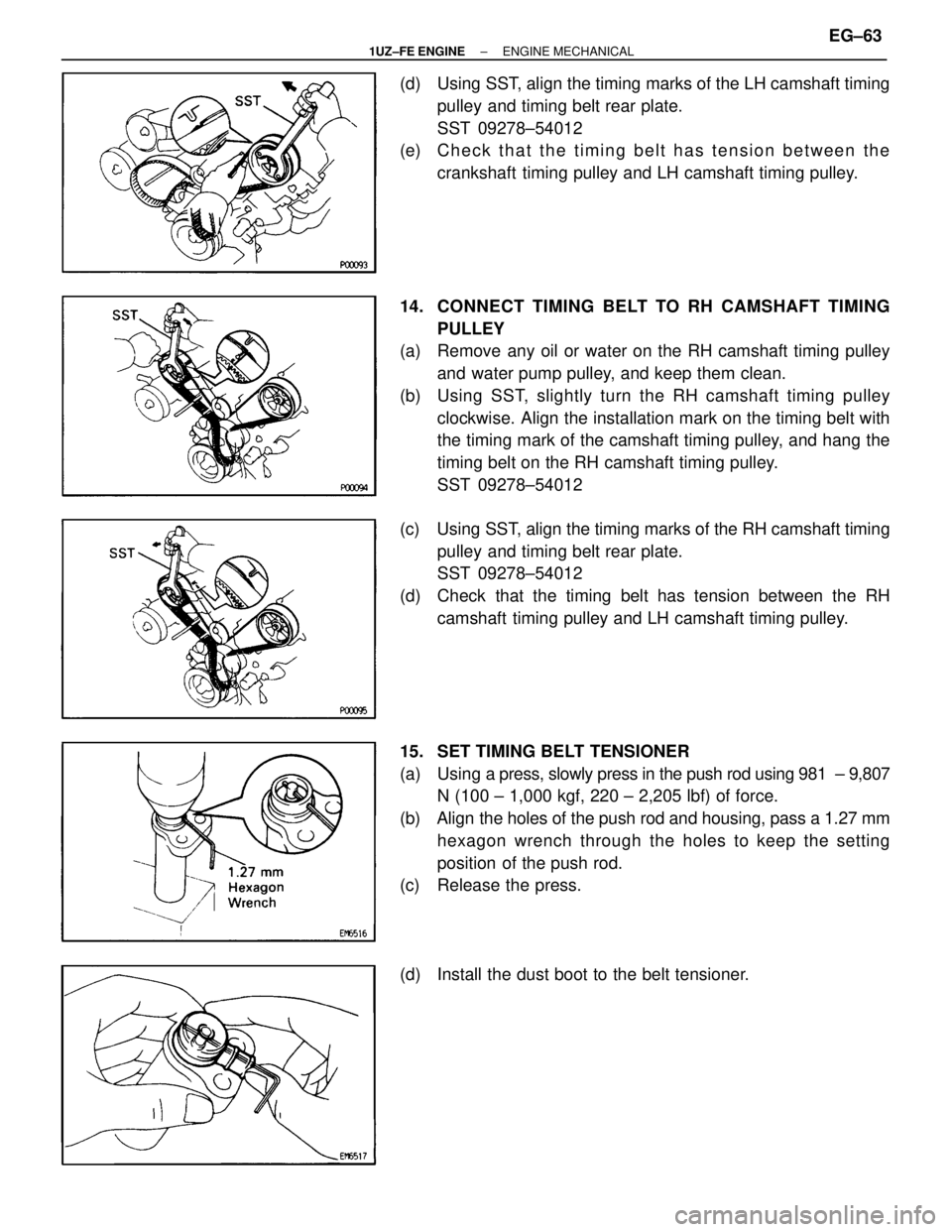
(d) Using SST, align the timing marks of the LH camshaft timingpulley and timing belt rear plate.
SST 09278±54012
(e) C h e c k t h a t t h e t i m i n g b e l t h a s t e n s i o n b e t w e e n t h e
crankshaft timing pulley and LH camshaft timing pulley.
14. CONNECT TIMING BELT TO RH CAMSHAFT TIMING PULLEY
(a) Remove any oil or water on the RH camshaft timing pulley
and water pump pulley, and keep them clean.
(b) Using SST, slightly turn the RH camshaft timing pulley clockwise. Align the installation mark on the timing belt with
the timing mark of the camshaft timing pulley, and hang the
timing belt on the RH camshaft timing pulley.
SST 09278±54012
(c) Using SST, align the timing marks of the RH camshaft timing pulley and timing belt rear plate.
SST 09278±54012
(d) Check that the timing belt has tension between the RH camshaft timing pulley and LH camshaft timing pulley.
15. SET TIMING BELT TENSIONER
(a) Using a press, slowly press in the push rod using 981 ± 9,807
N (100 ± 1,000 kgf, 220 ± 2,205 lbf) of force.
(b) Align the holes of the push rod and housing, pass a 1.27 mm hexagon wrench through the holes to keep the setting
position of the push rod.
(c) Release the press.
(d) Install the dust boot to the belt tensioner.
±
1UZ±FE ENGINE ENGINE MECHANICALEG±63
WhereEverybodyKnowsYourName
Page 1478 of 4087
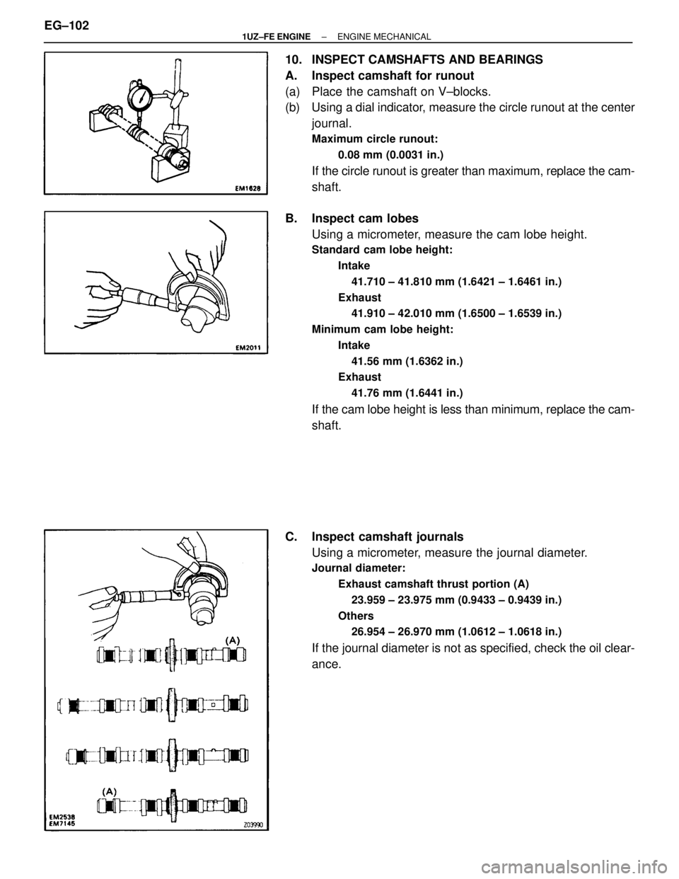
10. INSPECT CAMSHAFTS AND BEARINGS
A. Inspect camshaft for runout
(a) Place the camshaft on V±blocks.
(b) Using a dial indicator, measure the circle runout at the centerjournal.
Maximum circle runout:
0.08 mm (0.0031 in.)
If the circle runout is greater than maximum, replace the cam-
shaft.
B. Inspect cam lobes Using a micrometer, measure the cam lobe height.
Standard cam lobe height:
Intake41.710 ± 41.810 mm (1.6421 ± 1.6461 in.)
Exhaust 41.910 ± 42.010 mm (1.6500 ± 1.6539 in.)
Minimum cam lobe height: Intake41.56 mm (1.6362 in.)
Exhaust
41.76 mm (1.6441 in.)
If the cam lobe height is less than minimum, replace the cam-
shaft.
C. Inspect camshaft journals Using a micrometer, measure the journal diameter.
Journal diameter:
Exhaust camshaft thrust portion (A)23.959 ± 23.975 mm (0.9433 ± 0.9439 in.)
Others 26.954 ± 26.970 mm (1.0612 ± 1.0618 in.)
If the journal diameter is not as specified, check the oil clear-
ance.
EG±102
±
1UZ±FE ENGINE ENGINE MECHANICAL
WhereEverybodyKnowsYourName
Page 1479 of 4087
D. Inspect camshaft bearingsCheck that bearings for flaking and scoring.
If the bearings are damaged, replace the bearing caps and
cylinder head a set.
E. Inspect camshaft gear spring Using a vernier caliper measure the free distance between
the spring ends.
Free distance:
18.2 ± 18.8 mm (0.712 ± 0.740 in.)
If the free distance is not as specified, replace the gear
spring.
F. Inspect camshaft journal oil clearance
(a) Clean the bearing caps and camshaft journals.
(b) Place the camshafts on the cylinder head.
(c) Lay a strip of Plasti gage across each of the camshaft
journals.
(d) Install the bearing caps. (See step 7 on pages EG±114 to 120)
Torque: 16 N Vm (160 kgf Vcm, 12 ft Vlbf)
NOTICE: Do not turn the camshaft.
(e) Remove the bearing caps.
±
1UZ±FE ENGINE ENGINE MECHANICALEG±103
WhereEverybodyKnowsYourName
Page 1484 of 4087
2. INSTALL VALVES
(a) Using SST, push in a new oil seal.SST 09201±41020
(b) Install the following parts: (1) Valve
(2) Spring seat
(3) Valve spring
(4) Spring retainer
(c) Using SST, compress the valve spring and place the 2 keepers around the valve stem.
SST 09202±70010
(d) Using a plastic±faced hammer, lightly tap the valve stem tip to assure proper fit.
3. INSTALL VALVE LIFTERS AND SHIMS
(a) Install the valve lifter and shim.
(b) Check that the valve lifter rotates smoothly by hand.
EG±108
±
1UZ±FE ENGINE ENGINE MECHANICAL
WhereEverybodyKnowsYourName
Page 1492 of 4087
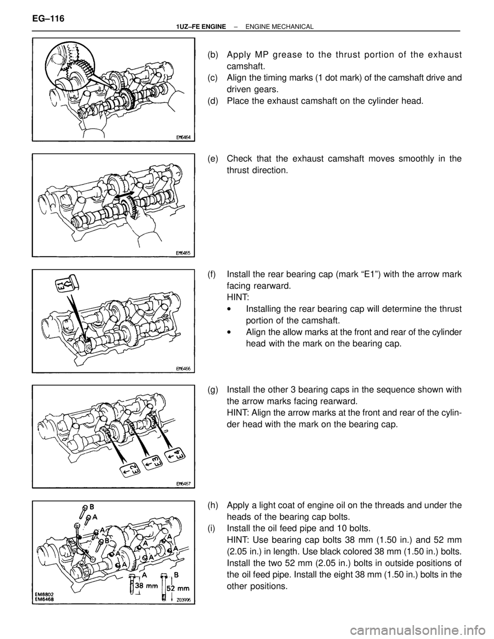
(b) Apply MP grease to the thrust portion of the exhaustcamshaft.
(c) Align the timing marks (1 dot mark) of the camshaft drive and
driven gears.
(d) Place the exhaust camshaft on the cylinder head.
(e) Check that the exhaust camshaft moves smoothly in the thrust direction.
(f) Install the rear bearing cap (mark ªE1º) with the arrow mark facing rearward.
HINT:
wInstalling the rear bearing cap will determine the thrust
portion of the camshaft.
w Align the allow marks at the front and rear of the cylinder
head with the mark on the bearing cap.
(g) Install the other 3 bearing caps in the sequence shown with the arrow marks facing rearward.
HINT: Align the arrow marks at the front and rear of the cylin-
der head with the mark on the bearing cap.
(h) Apply a light coat of engine oil on the threads and under the heads of the bearing cap bolts.
(i) Install the oil feed pipe and 10 bolts.
HINT: Use bearing cap bolts 38 mm (1.50 in.) and 52 mm
(2.05 in.) in length. Use black colored 38 mm (1.50 in.) bolts.
Install the two 52 mm (2.05 in.) bolts in outside positions of
the oil feed pipe. Install the eight 38 mm (1.50 in.) bolts in the
other positions.
EG±116
±
1UZ±FE ENGINE ENGINE MECHANICAL
WhereEverybodyKnowsYourName
Page 1496 of 4087
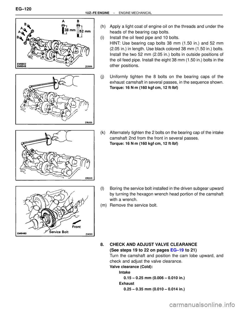
(h) Apply a light coat of engine oil on the threads and under theheads of the bearing cap bolts.
(i) Install the oil feed pipe and 10 bolts.
HINT: Use bearing cap bolts 38 mm (1.50 in.) and 52 mm
(2.05 in.) in length. Use black colored 38 mm (1.50 in.) bolts.
Install the two 52 mm (2.05 in.) bolts in outside positions of
the oil feed pipe. Install the eight 38 mm (1.50 in.) bolts in the
other positions.
(j) Uniformly tighten the 8 bolts on the bearing caps of the exhaust camshaft in several passes, in the sequence shown.
Torque: 16 N Vm (160 kgf Vcm, 12 ft Vlbf)
(k) Alternately ti ghten the 2 bolts on the bearing cap of the intake
camshaft 2nd from the front in several passes.
Torque: 16 N Vm (160 kgf Vcm, 12 ft Vlbf)
(l) Boring the service bolt installed in the driven subgear upward
by turning the hexagon wrench head portion of the camshaft
with a wrench.
(m) Remove the service bolt.
8. CHECK AND ADJUST VALVE CLEARANCE (See steps 19 to 22 on pages EG±19 to 21)
Turn the camshaft and position the cam lobe upward, and
check and adjust the valve clearance.
Valve clearance (Cold):
Intake0.15 ± 0.25 mm (0.006 ± 0.010 in.)
Exhaust 0.25 ± 0.35 mm (0.010 ± 0.014 in.)
EG±120±
1UZ±FE ENGINE ENGINE MECHANICAL
WhereEverybodyKnowsYourName
Page 1532 of 4087
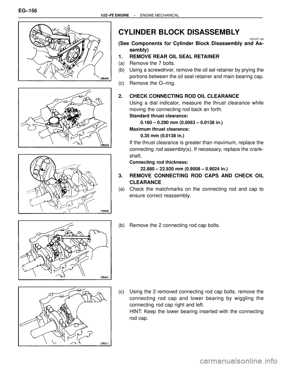
CYLINDER BLOCK DISASSEMBLY
EG1KT±04
(See Components for Cylinder Block Disassembly and As-sembly)
1. REMOVE REAR OIL SEAL RETAINER
(a) Remove the 7 bolts.
(b) Using a screwdriver, remove the oil sel retainer by prying the portions between the oil seal retainer and main bearing cap.
(c) Remove the O±ring.
2. CHECK CONNECTING ROD OIL CLEARANCE Using a dial indicator, measure the thrust clearance while
moving the connecting rod back an forth.
Standard thrust clearance:
0.160 ± 0.290 mm (0.0063 ± 0.0138 in.)
Maximum thrust clearance: 0.35 mm (0.0138 in.)
If the thrust clearance is greater than maximum, replace the
connecting rod assembly(s). If necessary, replace the crank-
shaft.
Connecting rod thickness:
22.880 ± 22.920 mm (0.9008 ± 0.9024 in.)
3. REMOVE CONNECTING ROD CAPS AND CHECK OILCLEARANCE
(a) Check the matchmarks on the connecting rod and cap to ensure correct reassembly.
(b) Remove the 2 connecting rod cap bolts.
(c) Using the 2 removed connecting rod cap bolts, remove the connecting rod cap and lower bearing by wiggling the
connecting rod cap right and left.
HINT: Keep the lower bearing inserted with the connecting
rod cap.
EG±156
±
1UZ±FE ENGINE ENGINE MECHANICAL
WhereEverybodyKnowsYourName