Page 378 of 4087
6. INSTALL EXTENSION HOUSING REAR OIL SEAL
(a) Coat the lip of oil seal with MP grease.
(b) Using SST and a hammer, drive in a new oil seal with the lipfacing downward.
SST 09309±37010
Oil seal depth from flat end:
0±0.3 mm (0±0.012 in.)
7. INSTALL TRANSMISSION OUTPUT FLANGE
(a) Using SST and a hammer, drive in a new oil seal.SST 09517±36010
(b) Install the output flange and 2 washers.
(c) Using SST, install and torque a new nut. SST 09060±20010
Torque: 123 N Vm (1,250 kgf Vcm, 90 ft Vlbf)
HINT: Shift the shift lever to the P position.
(d) Using a hammer and chisel, stake the nut.
8. INSTALL PROPELLER SHAFT (See pages PR±12)
9. INSTALL FRONT EXHAUST PIPE AND HEAT INSULATOR (See page EG±204)
10. FILL WITH ATF
11. CHECK FLUID LEVEL (See page AT±47)
±
A304E (1UZ±FE) AUTOMATIC TRANSMISSION EXTENSION HOUSINGAT±15
WhereEverybodyKnowsYourName
Page 385 of 4087
4. CONNECT SOLENOID VALVE CONNECTORS
5. INSTALL OIL STRAINER AND GASKETSInstall the oil strainer and torque the 3 bolts.
Torque: 10 N Vm (100 kgf Vcm, 7 ft Vlbf)
6. INSTALL OIL PAN
(a) Install the 4 magnets in the indentations of the oil pan, as
shown in the illustration.
(b) Remove any FIPG material and be careful not to drop oil on the contacting surfaces of the transmission case and oil pan.
(c) Apply FIPG to the oil pan, as shown in the illustration.
FIPG:
Part No. 08826±00090, THREE BOND 1281 or equivalent
(d) Install the oil pan to the transmission case and torque the 19bolts.
Torque: 7.4 N Vm (75 kgf Vcm, 65 in. Vlbf)
7. INSTALL FRONT EXHAUST PIPE
(See page EG±204)
8. CHECK FLUID LEVEL
AT±22
±
A304E (1UZ±FE) AUTOMATIC TRANSMISSION VALVE BODY
WhereEverybodyKnowsYourName
Page 395 of 4087

HOW TO PROCEED WITH TROUBLESHOOTING
AT09N±0D
1. CUSTOMER PROBLEM ANALYSISUsing the customer problem analysis check sheet for reference, ask the c\
ustomer in as much detail as
possible about the problem.
2. CHECK AND CLEAR THE DIAGNOSTIC TROUBLE CODES (PRECHECK) Before confirming the problem symptom, first check if there are any diagnostic\
trouble malfunction codes
stored in memory. When there are malfunction codes, make a note of them, then clear them\
and proceed
to ª3. Problem Symptom Confirmationº.
3. PROBLEM SYMPTOM CONFIRMATION Confirm the problem symptoms.
4. SYMPTOM SIMULATION If the problem does not reappear, be sure to simulate the problem by mainly checking the circuits indica\
ted
by the diagnostic trouble code in step 2., using ªProblem Simulation me\
thodº.
5. DIAGNOSTIC TROUBLE CODE CHECK Check the diagnostic trouble codes. Check if there is abnormality in the\
sensors or the wire harness.
If a malfunction code is output, proceed to ª6. Diagnostic Trouble Code Chartº.
If the normal code is output, proceed to ª11. Matrix Chart of Problem Symptomsº.
Be sure to proceed to ª6. Diagnostic Trouble Code Chartº after the steps 2. and 3. are completed.
If troubleshooting is attempted only by following the malfunction code sto\
red in the memory is output, errors
could be made in the diagnosis.
6. DIAGNOSTIC TROUBLE CODE CHART If a malfunction code is confirmed in the diagnostic trouble code check, p\
roceed to the inspection proce-
dure indicated by the matrix chart for each diagnostic trouble code.
7. PRELIMINARY CHECK Carry out a preliminary check of the transmission oil level, throttle ca\
ble adjustment, etc.
8. SHIFT POSITION SIGNAL CHECK
Carry out the shift position signal check when the transmission gears do\
not up±shift, down±shift or lock±
up. This is to check the output condition from the ECM to each solenoid. If the r\
esults are NG, then it is
likely that the trouble is in the electrical system (particularly in th\
e sensors or the ECM).
Proceed to Part 1 (Electrical System) under ª11. Matrix Chart of Problem Symptomsº. If all the circuits speci-
fied in Part 1 are OK, check the ECM and replace it.
9. MECHANICAL SYSTEM TEST (Stall Test, Time Lag Test, Line Pressure Test, Accumulator Back Pressure Test)
If the malfunction is found in the stall test, time lag test, line press\
ure test or accumulator back pressure
test, check the parts indicated in the respective tests. If the problem is th\
at ªshift shock is largeº, perform
the accumulator back pressure test.
10. MANUAL SHIFTING TEST If the results of the manual driving test are NG, it is likely that the trouble is in the mechanical system or
hydraulic system. Proceed to Part 2 (Mechanical System) under the Matrix Chart \
of Problem Symptoms.
AT±32
±
A304E (1UZ±FE) AUTOMATIC TRANSMISSION TROUBLESHOOTING
WhereEverybodyKnowsYourName
Page 559 of 4087

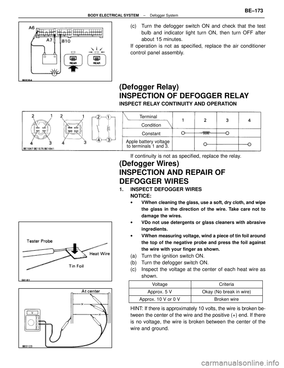
(c) Turn the defogger switch ON and check that the testbulb and indicator light turn ON, then turn OFF after
about 15 minutes.
If operation is not as specified, replace the air conditioner
control panel assembly.
(Defogger Relay)
INSPECTION OF DEFOGGER RELAY
INSPECT RELAY CONTINUITY AND OPERATION
Terminal
ConditionConstant
Apple battery voltage to terminals 1 and 3.
If continuity is not as specified, replace the relay.
(Defogger Wires)
INSPECTION AND REPAIR OF
DEFOGGER WIRES
1. INSPECT DEFOGGER WIRES
NOTICE:
w VWhen cleaning the glass, use a soft, dry cloth, and wipe
the glass in the direction of the wire. Take care not to
damage the wires.
w VDo not use detergents or glass cleaners with abrasive
ingredients.
w VWhen measuring voltage, wind a piece of tin foil around
the top of the negative probe and press the foil against
the wire with your finger as shown.
(a) Turn the ignition switch ON.
(b) Turn the defogger switch ON.
(c) Inspect the voltage at the center of each heat wire as
shown.
VoltageCriteria
Approx. 5 VOkay (No break in wire)
Approx. 10 V or 0 VBroken wire
HINT: If there is approximately 10 volts, the wire is broken be-
tween the center of the wire and the positive (+) end. If there
is no voltage, the wire is broken between the center of the
wire and ground.
±
BODY ELECTRICAL SYSTEM Defogger SystemBE±173
WhereEverybodyKnowsYourName
Page 561 of 4087
INSPECTION OF MIRROR DEFOGGER
INSPECT MIRROR DEFOGGER(a) Connect the positive (+) lead from the battery to terminal
7 and the negative (±) lead to terminal 8.
(b) Check that the mirror becomes warm.
HINT: It will take a short time for the mirror to become warm.
If the mirror does not become warm, replace the mirror as-
sembly.
Troubleshooting
You will find the cause of trouble more easily using the table shown below. In this table, the number indicate
the order priority of the causes in trouble. Check each part in the order s\
hown. If necessary, replace the parts.
See pageBE±4 ,20BE±4,20BE±4,22BE±172BE±173 ±±BE±173 ±±BE±174
TroubleParts
name
HEATER FuseMIR±HTR FuseDEFOG FuseDefogger SwitchDefogger RelayWire HarnessDefogger WiresCKE CoilMirror Defogger
All defogger systems do not operate.11234
Rear window defogger does not operate.312
Mirror Defogger does not operate.132
±
BODY ELECTRICAL SYSTEM Defogger SystemBE±175
WhereEverybodyKnowsYourName
Page 602 of 4087

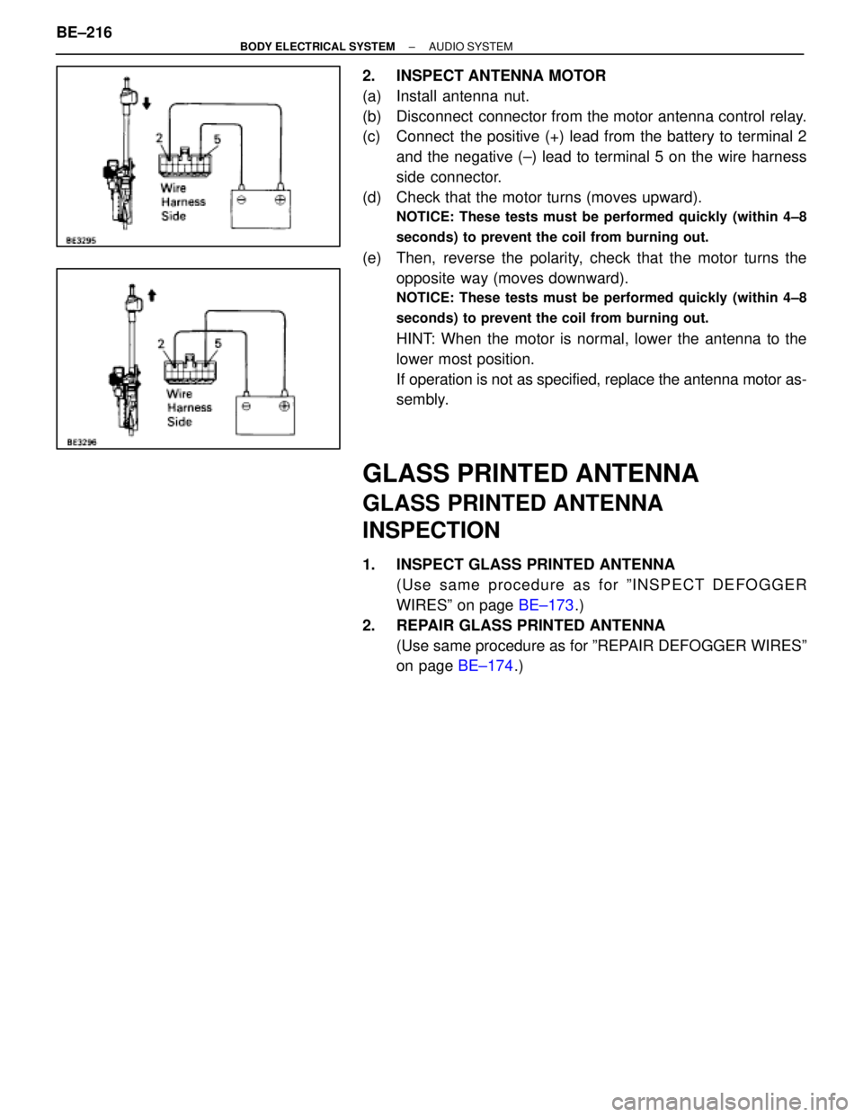
2. INSPECT ANTENNA MOTOR
(a) Install antenna nut.
(b) Disconnect connector from the motor antenna control relay.
(c) Connect the positive (+) lead from the battery to terminal 2and the negative (±) lead to terminal 5 on the wire harness
side connector.
(d) Check that the motor turns (moves upward).
NOTICE: These tests must be performed quickly (within 4±8
seconds) to prevent the coil from burning out.
(e) Then, reverse the polarity, check that the motor turns the opposite way (moves downward).
NOTICE: These tests must be performed quickly (within 4±8
seconds) to prevent the coil from burning out.
HINT: When the motor is normal, lower the antenna to the
lower most position.
If operation is not as specified, replace the antenna motor as-
sembly.
GLASS PRINTED ANTENNA
GLASS PRINTED ANTENNA
INSPECTION
1. INSPECT GLASS PRINTED ANTENNA(Use same procedure as for ºINSPECT DEFOGGER
WIRESº on page BE±173.)
2. REPAIR GLASS PRINTED ANTENNA (Use same procedure as for ºREPAIR DEFOGGER WIRESº
on page BE±174.)
BE±216
±
BODY ELECTRICAL SYSTEM AUDIO SYSTEM
WhereEverybodyKnowsYourName
Page 849 of 4087

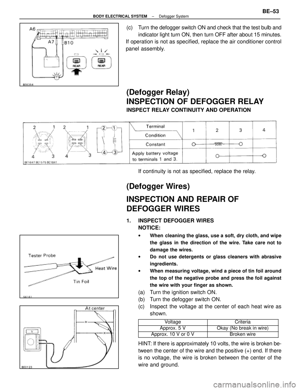
(c) Turn the defogger switch ON and check that the test bulb andindicator light turn ON, then turn OFF after about 15 minutes.
If operation is not as specified, replace the air conditioner control
panel assembly.
(Defogger Relay)
INSPECTION OF DEFOGGER RELAY
INSPECT RELAY CONTINUITY AND OPERATION
If continuity is not as specified, replace the relay.
(Defogger Wires)
INSPECTION AND REPAIR OF
DEFOGGER WIRES
1. INSPECT DEFOGGER WIRESNOTICE:
w When cleaning the glass, use a soft, dry cloth, and wipe
the glass in the direction of the wire. Take care not to
damage the wires.
w Do not use detergents or glass cleaners with abrasive
ingredients.
w When measuring voltage, wind a piece of tin foil around
the top of the negative probe and press the foil against
the wire with your finger as shown.
(a) Turn the ignition switch ON.
(b) Turn the defogger switch ON.
(c) Inspect the voltage at the center of each heat wire as
shown.
���������� ����������Voltage���������� ����������Criteria
����������Approx. 5 V����������Okay (No break in wire)���������� ����������Approx. 10 V or 0 V���������� ����������Broken wire
HINT: If there is approximately 10 volts, the wire is broken be-
tween the center of the wire and the positive (+) end. If there
is no voltage, the wire is broken between the center of the
wire and ground.
±
BODY ELECTRICAL SYSTEM Defogger SystemBE±53
WhereEverybodyKnowsYourName
Page 891 of 4087

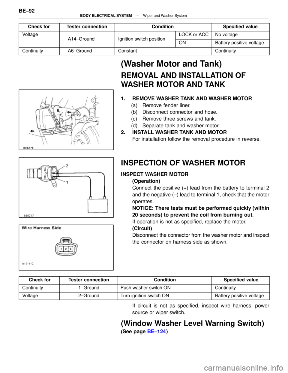
Check forTester connectionConditionSpecified value
VoltageA14±GroundIgnition switchpositionLOCK or ACCNo voltageA14±GroundIgnition switch positionONBattery positive voltage
ContinuityA6±GroundConstantContinuity
(Washer Motor and Tank)
REMOVAL AND INSTALLATION OF
WASHER MOTOR AND TANK
1. REMOVE WASHER TANK AND WASHER MOTOR(a) Remove fender liner.
(b) Disconnect connector and hose.
(c) Remove three screws and tank.
(d) Separate tank and washer motor.
2. INSTALL WASHER TANK AND MOTOR For installation follow the removal procedure in reverse.
INSPECTION OF WASHER MOTOR
INSPECT WASHER MOTOR
(Operation)
Connect the positive (+) lead from the battery to terminal 2
and the negative (±) lead to terminal 1, check that the motor
operates.
NOTICE: There tests must be performed quickly (within
20 seconds) to prevent the coil from burning out.
If operation is not as specified, replace the motor.
(Circuit)
Disconnect the connector from the washer motor and inspect
the connector on harness side as shown.
Check forTester connectionConditionSpecified value
Continuity1±GroundPush washer switch ONContinuity
Voltage2±GroundTurn ignition switch ONBattery positive voltage
If circuit is not as specified, inspect wire harness, power
source or wiper switch.
(Window Washer Level Warning Switch)
(See page BE±124)
BE±92
±
BODY ELECTRICAL SYSTEM Wiper and Washer System
WhereEverybodyKnowsYourName