Page 2296 of 4087
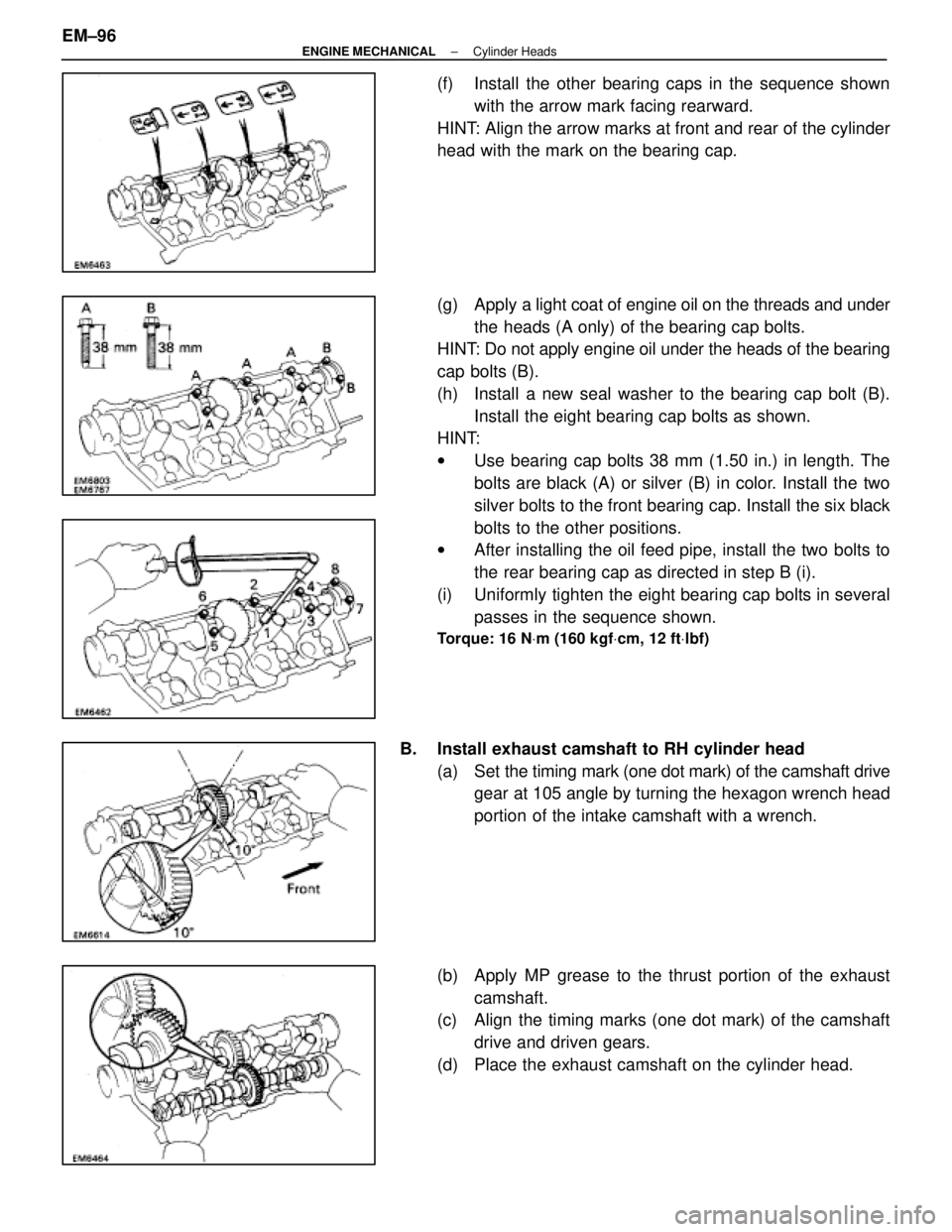
(f) Install the other bearing caps in the sequence shownwith the arrow mark facing rearward.
HINT: Align the arrow marks at front and rear of the cylinder
head with the mark on the bearing cap.
(g) Apply a light coat of engine oil on the threads and under
the heads (A only) of the bearing cap bolts.
HINT: Do not apply engine oil under the heads of the bearing
cap bolts (B).
(h) Install a new seal washer to the bearing cap bolt (B).
Install the eight bearing cap bolts as shown.
HINT:
w Use bearing cap bolts 38 mm (1.50 in.) in length. The
bolts are black (A) or silver (B) in color. Install the two
silver bolts to the front bearing cap. Install the six black
bolts to the other positions.
w After installing the oil feed pipe, install the two bolts to
the rear bearing cap as directed in step B (i).
(i) Uniformly tighten the eight bearing cap bolts in several passes in the sequence shown.
Torque: 16 N Vm (160 kgf Vcm, 12 ft Vlbf)
B. Install exhaust camshaft to RH cylinder head
(a) Set the timing mark ( one dot mark) of the camshaft drive
gear at 105 angle by turning the hexagon wrench head
portion of the intake camshaft with a wrench.
(b) Apply MP grease to the thrust portion of the exhaust camshaft.
(c) Align the timing marks (one dot mark) of the camshaft
drive and driven gears.
(d) Place the exhaust camshaft on the cylinder head.
EM±96
±
ENGINE MECHANICAL Cylinder Heads
WhereEverybodyKnowsYourName
Page 2297 of 4087
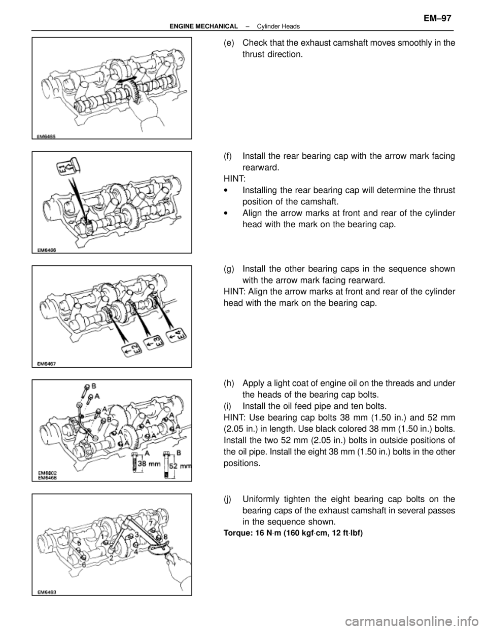
(e) Check that the exhaust camshaft moves smoothly in the
thrust direction.
(f) Install the rear bearing cap with the arrow mark facing rearward.
HINT:
w Installing the rear bearing cap will determine the thrust
position of the camshaft.
w Align the arrow marks at front and rear of the cylinder
head with the mark on the bearing cap.
(g) Install the other bearing caps in the sequence shown with the arrow mark facing rearward.
HINT: Align the arrow marks at front and rear of the cylinder
head with the mark on the bearing cap.
(h) Apply a light coat of engine oil on the threads and under
the heads of the bearing cap bolts.
(i) Install the oil feed pipe and ten bolts.
HINT: Use bearing cap bolts 38 mm (1.50 in.) and 52 mm
(2.05 in.) in length. Use black colored 38 mm (1.50 in.) bolts.
Install the two 52 mm (2.05 in.) bolts in outside positions of
the oil pipe. Install the eight 38 mm (1.50 in.) bolts in the other
positions.
(j) Uniformly tighten the eight bearing cap bolts on the bearing caps of the exhaust camshaft in several passes
in the sequence shown.
Torque: 16 N Vm (160 kgf Vcm, 12 ft Vlbf)
±
ENGINE MECHANICAL Cylinder HeadsEM±97
WhereEverybodyKnowsYourName
Page 2299 of 4087
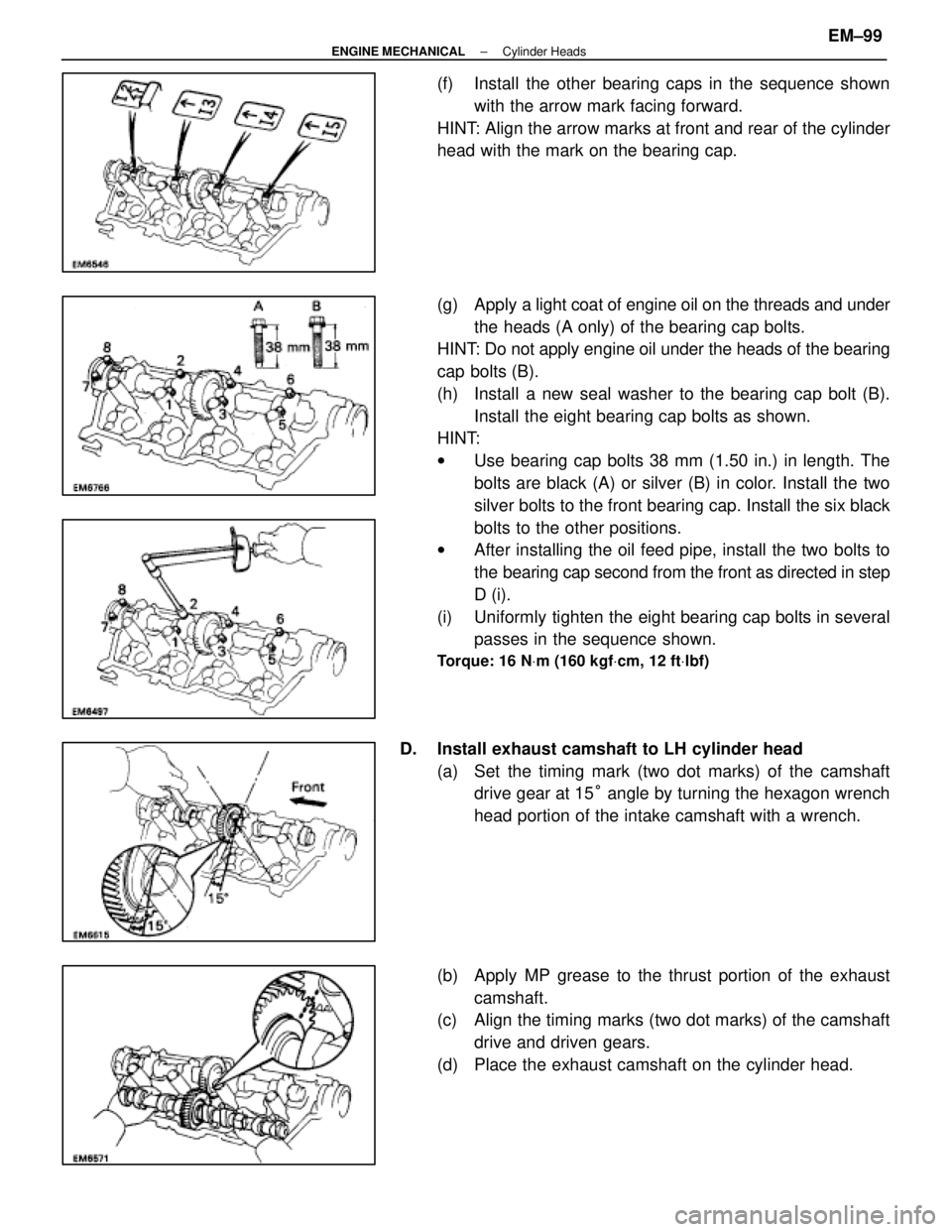
(f) Install the other bearing caps in the sequence shownwith the arrow mark facing forward.
HINT: Align the arrow marks at front and rear of the cylinder
head with the mark on the bearing cap.
(g) Apply a light coat of engine oil on the threads and under
the heads (A only) of the bearing cap bolts.
HINT: Do not apply engine oil under the heads of the bearing
cap bolts (B).
(h) Install a new seal washer to the bearing cap bolt (B).
Install the eight bearing cap bolts as shown.
HINT:
w Use bearing cap bolts 38 mm (1.50 in.) in length. The
bolts are black (A) or silver (B) in color. Install the two
silver bolts to the front bearing cap. Install the six black
bolts to the other positions.
w After installing the oil feed pipe, install the two bolts to
the bearing cap second from the front as directed in step
D (i).
(i) Uniformly tighten the eight bearing cap bolts in several passes in the sequence shown.
Torque: 16 N Vm (160 kgf Vcm, 12 ft Vlbf)
D. Install exhaust camshaft to LH cylinder head
(a) Set the timing mark (two dot marks) of the camshaftdrive gear at 15 ° angle by turning the hexagon wrench
head portion of the intake camshaft with a wrench.
(b) Apply MP grease to the thrust portion of the exhaust camshaft.
(c) Align the timing marks (two dot marks) of the camshaft
drive and driven gears.
(d) Place the exhaust camshaft on the cylinder head.
±
ENGINE MECHANICAL Cylinder HeadsEM±99
WhereEverybodyKnowsYourName
Page 2300 of 4087
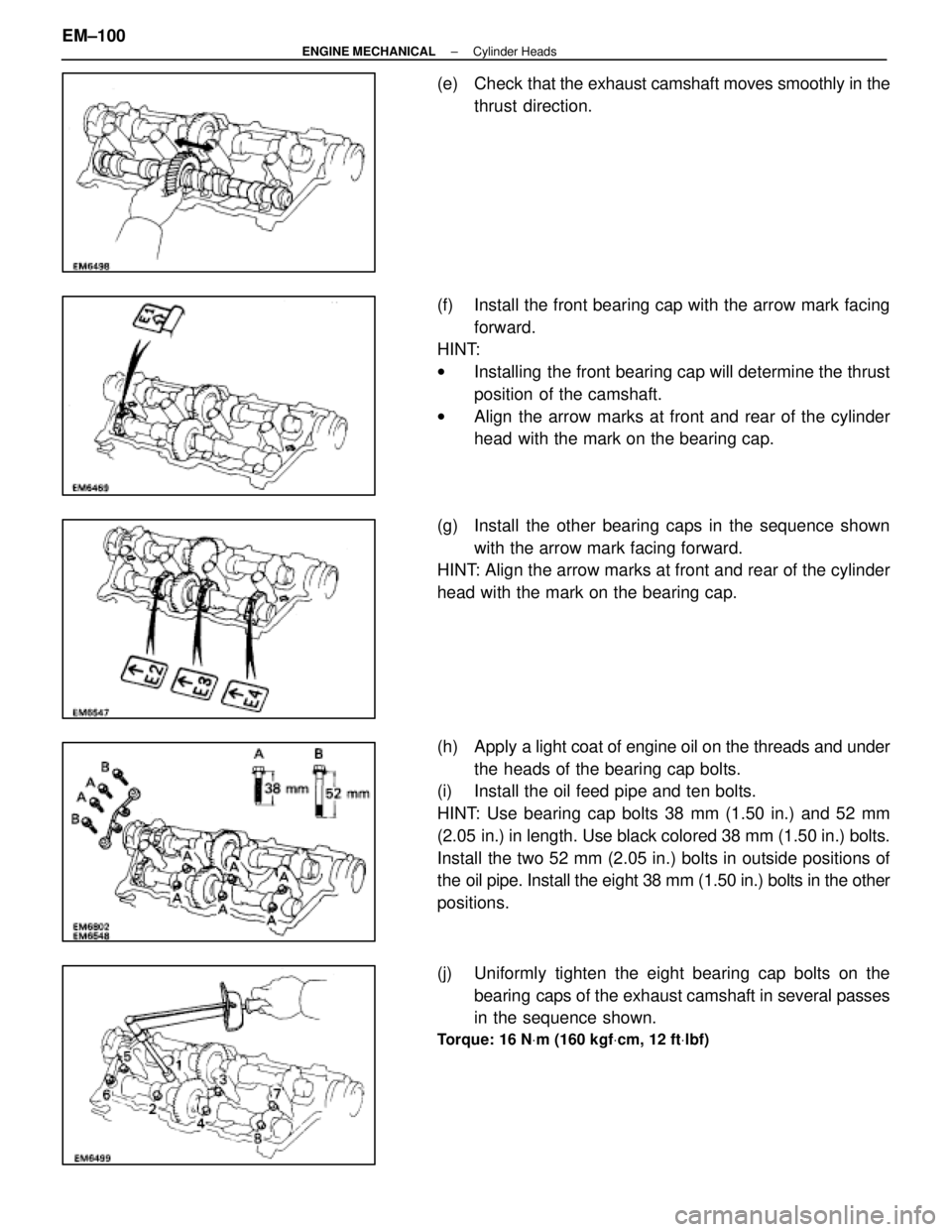
(e) Check that the exhaust camshaft moves smoothly in the
thrust direction.
(f) Install the front bearing cap with the arrow mark facing forward.
HINT:
w Installing the front bearing cap will determine the thrust
position of the camshaft.
w Align the arrow marks at front and rear of the cylinder
head with the mark on the bearing cap.
(g) Install the other bearing caps in the sequence shown with the arrow mark facing forward.
HINT: Align the arrow marks at front and rear of the cylinder
head with the mark on the bearing cap.
(h) Apply a light coat of engine oil on the threads and under
the heads of the bearing cap bolts.
(i) Install the oil feed pipe and ten bolts.
HINT: Use bearing cap bolts 38 mm (1.50 in.) and 52 mm
(2.05 in.) in length. Use black colored 38 mm (1.50 in.) bolts.
Install the two 52 mm (2.05 in.) bolts in outside positions of
the oil pipe. Install the eight 38 mm (1.50 in.) bolts in the other
positions.
(j) Uniformly tighten the eight bearing cap bolts on the
bearing caps of the exhaust camshaft in several passes
in the sequence shown.
Torque: 16 N Vm (160 kgf Vcm, 12 ft Vlbf)
EM±100±
ENGINE MECHANICAL Cylinder Heads
WhereEverybodyKnowsYourName
Page 2304 of 4087

19. INSTALL REAR WATER BY±PASS JOINT(a) Install two new gaskets and the water by±pass joint with
the four nuts. Alternately tighten the nuts.
Torque: 18 N Vm (185 kgf Vcm, 13 ft Vlbf)
(b) Install the bolt holding the water by±pass pipe to the
engine hanger.
20. INSTALL FRONT WATER BY±PASS JOINT (a) Install two new gaskets and the water by±pass joint with
the four nuts. Alternately tighten the nuts.
Torque: 18 N Vm (185 kgf Vcm, 13 ft Vlbf)
(b) Install the engine wire clamp with the bolt.
(c) Connect the following connectors:
(1) Water temperature sensor connector
(2) Cold start injector time switch connector
(3) Water temperature sender gauge connector
21. INSTALL INTAKE MANIFOLD (a) Place two new gaskets on the cylinder heads with thewhite painted mark facing upward.
NOTICE: Align the port holes of the gasket and cylinder
head. Be careful of the installation direction.
(b) Place the intake manifold in position on the cylinder head with the arrow mark facing forward.
NOTICE: Be careful of the installation direction.
(c) Install and uniformly tighten the six mounting bolts and
four mounting nuts.
Torque: 18 N Vm (185 kgf Vcm, 13 ft Vlbf)
HINT: Use bolts 30 mm (1.18 in.) in length.
EM±104
±
ENGINE MECHANICAL Cylinder Heads
WhereEverybodyKnowsYourName
Page 2307 of 4087
25. INSTALL ENGINE WIRE TO INTAKE MANIFOLDInstall the engine wire with the two bolts.
26. TEMPORARILY INSTALL EGR PIPE TO RH CYLINDER HEAD
Temporarily install a new gasket and the EGR pipe with the
two bolts.
HINT: Use bolt 25 mm (0.98 in.) in length.
27. CONNECT FUEL RETURN HOSE TO FUEL RETURN PIPE
28. CONNECT FUEL INLET HOSE TO LH DELIVERY PIPE Connect the inlet hose with two new gaskets and the pulsa-
tion damper.
SST 09612±24012 (09617±24011)
Torque: 39 N Vm (400 kgf Vcm, 29 ft Vlbf)
33 N Vm (340 kgf Vcm, 24 ft Vlbf) for SST
HINT: Use a torque wrench with a fulcrum length of 30 cm
(11.81 in.).
29. CONNECT HEATER WATER HOSES Connect the following hoses:(1) Water hose to water by±pass pipe
(2) Water hose to rear water by±pass joint
30. INSTALL AIR INTAKE CHAMBER (a) Install the cold start injector, tube and wire assemblywith the three bolts.
Torque: 7.8 N Vm (80 kgf Vcm, 69 in. Vlbf)
±
ENGINE MECHANICAL Cylinder HeadsEM±107
WhereEverybodyKnowsYourName
Page 2308 of 4087
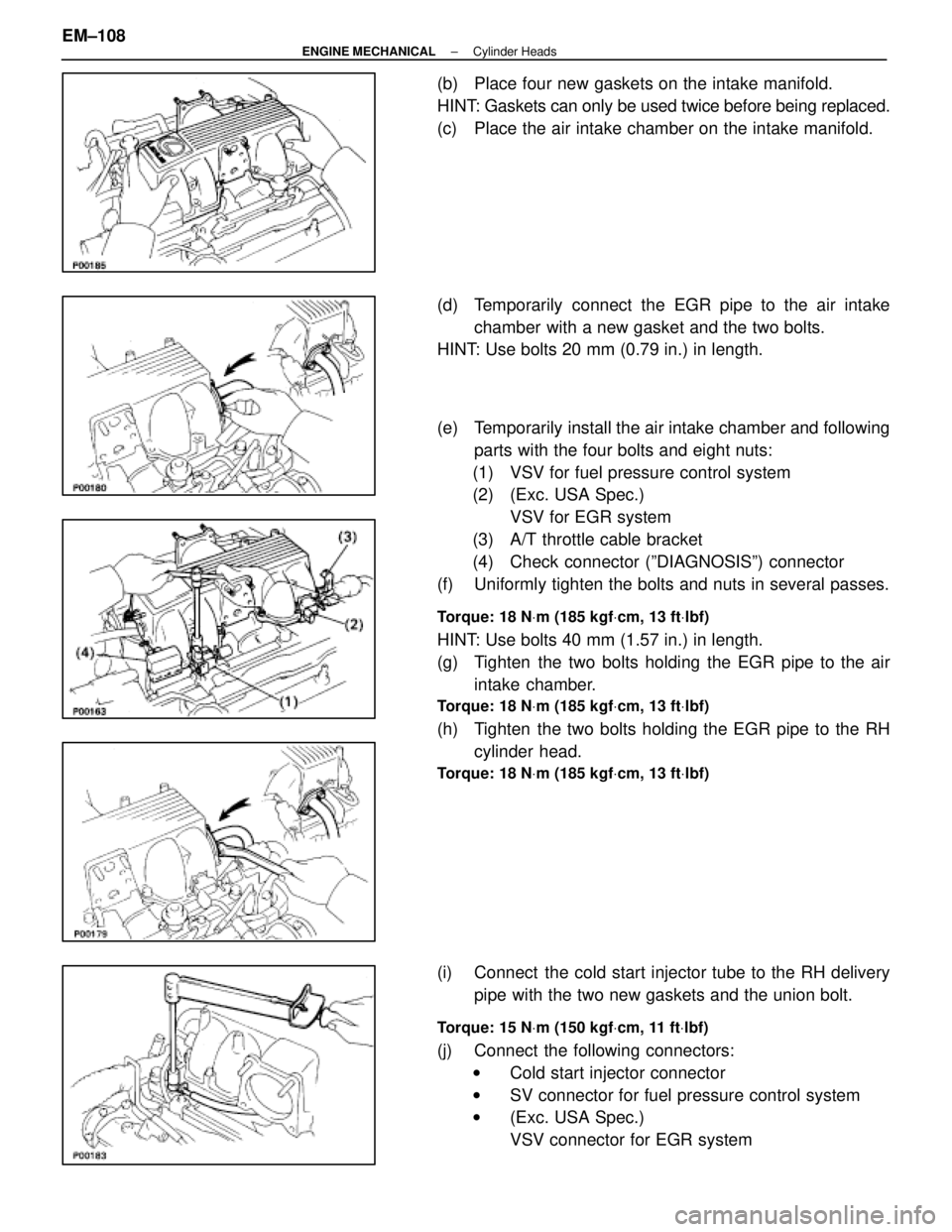
(b) Place four new gaskets on the intake manifold.
HINT: Gaskets can only be used twice before being replaced.
(c) Place the air intake chamber on the intake manifold.
(d) Temporarily connect the EGR pipe to the air intakechamber with a new gasket and the two bolts.
HINT: Use bolts 20 mm (0.79 in.) in length.
(e) Temporarily install the air intake chamber and following
parts with the four bolts and eight nuts:
(1) VSV for fuel pressure control system
(2) (Exc. USA Spec.) VSV for EGR system
(3) A/T throttle cable bracket
(4) Check connector (ºDIAGNOSISº) connector
(f) Uniformly tighten the bolts and nuts in several passes.
Torque: 18 N Vm (185 kgf Vcm, 13 ft Vlbf)
HINT: Use bolts 40 mm (1.57 in.) in length.
(g) Tighten the two bolts holding the EGR pipe to the air
intake chamber.
Torque: 18 N Vm (185 kgf Vcm, 13 ft Vlbf)
(h) Tighten the two bolts holding the EGR pipe to the RH
cylinder head.
Torque: 18 N Vm (185 kgf Vcm, 13 ft Vlbf)
(i) Connect the cold start injector tube to the RH delivery
pipe with the two new gaskets and the union bolt.
Torque: 15 N Vm (150 kgf Vcm, 11 ft Vlbf)
(j) Connect the following connectors:
w Cold start injector connector
w SV connector for fuel pressure control system
w (Exc. USA Spec.)
VSV connector for EGR system
EM±108
±
ENGINE MECHANICAL Cylinder Heads
WhereEverybodyKnowsYourName
Page 2309 of 4087
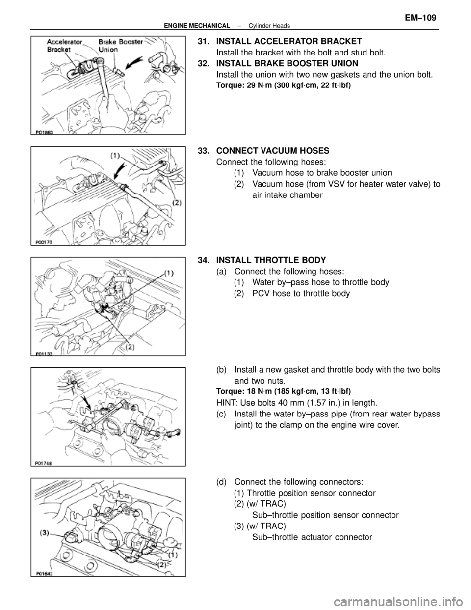
31. INSTALL ACCELERATOR BRACKETInstall the bracket with the bolt and stud bolt.
32. INSTALL BRAKE BOOSTER UNION Install the union with two new gaskets and the union bolt.
Torque: 29 N Vm (300 kgf Vcm, 22 ft Vlbf)
33. CONNECT VACUUM HOSES
Connect the following hoses:(1) Vacuum hose to brake booster union
(2) Vacuum hose (from VSV for heater water valve) to
air intake chamber
34. INSTALL THROTTLE BODY (a) Connect the following hoses:(1) Water by±pass hose to throttle body
(2) PCV hose to throttle body
(b) Install a new gasket and throttle body with the two bolts and two nuts.
Torque: 18 N Vm (185 kgf Vcm, 13 ft Vlbf)
HINT: Use bolts 40 mm (1.57 in.) in length.
(c) Install the water by±pass pipe (from rear water bypass
joint) to the clamp on the engine wire cover.
(d) Connect the following connectors: (1) Throttle position sensor connector
(2) (w/ TRAC) Sub±throttle position sensor connector
(3) (w/ TRAC) Sub±throttle actuator connector
±
ENGINE MECHANICAL Cylinder HeadsEM±109
WhereEverybodyKnowsYourName