Page 2561 of 4087
REPLACEMENT OF ENGINE OIL
AND OIL FILTER
CAUTION:
wProlonged and repeated contact with mineral oil will
result in the removal of natural fats from the skin, leading
to dryness, irritation and dermatitis. In addition, used
engine oil contains potentially harmful contaminants
which may cause skin cancer.
w Care should be taken, therefore, when changing engine,
oil to minimize the frequency and length of time your skin
is exposed to used engine oil. Protective clothing and
gloves, that cannot be penetrated by oil, should be worn.
The skin should be thoroughly washed with soap and
water, or use waterless hand cleaner, to remove any used
engine oil. Do not use gasoline, thinners, or solvents.
w In order to preserve the environment, used oil and used
oil filter must be disposed of only at designated disposal
sites.
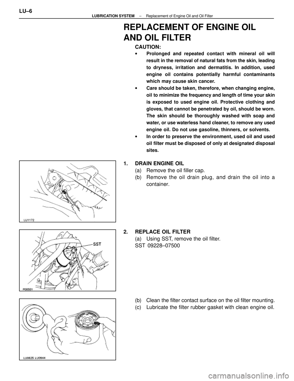
1. DRAIN ENGINE OIL
(a) Remove the oil filler cap.
(b) Remove the oil drain plug, and drain the oil into acontainer.
2. REPLACE OIL FILTER (a) Using SST, remove the oil filter.
SST 09228±07500
(b) Clean the filter contact surface on the oil filter mounting.
(c) Lubricate the filter rubber gasket with clean engine oil.
LU±6
±
LUBRICATION SYSTEM Replacement of Engine Oil and Oil Filter
WhereEverybodyKnowsYourName
Page 2571 of 4087
(e) Install the oil pump with the eight bolts.
Torque:12 mm head 16 N Vm (160 kgf Vcm, 12 ft Vlbf)
14 mm head 30 N Vm (310 kgf Vcm, 22 ft Vlbf)
HINT: Each bolt length is indicated in the illustration.
Bolt length:
A 50 mm (1.97 in.) for 12 mm head
B 106 mm (4.17 in.) for 12 mm head
C 30 mm (1.18 in.) for 12 mm head
D 40 mm (1.57 in.) for 14 mm head
2. INSTALL ENGINE SPEED SENSOR (a) Install the speed sensor with the bolt.
Torque: 6.4 N Vm (65 kgf Vcm, 56 in. Vlbf)
(b) Connect the speed sensor connector.
3. INSTALL OIL FILTER BRACKET (a) Place a new gasket in position on the oil filter bracket.
(b) Install the oil filter bracket with the two bolts and studbolt.
Torque: 18 N Vm (185 kgf Vcm, 13 ft Vlbf)
(c) Connect the oil pressure switch connector.
4. INSTALL OIL STRAINER Install a new gasket and the oil strainer with the two bolts and
two nuts.
Torque: 7.8 N Vm (80 kgf Vcm, 69 in. Vlbf)
LU±16±
LUBRICATION SYSTEM Oil Pump
WhereEverybodyKnowsYourName
Page 2572 of 4087
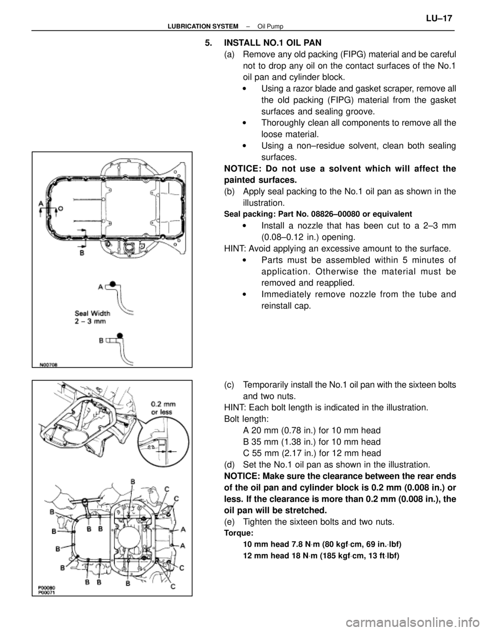
5. INSTALL NO.1 OIL PAN(a) Remove any old packing (FIPG) material and be carefulnot to drop any oil on the contact surfaces of the No.1
oil pan and cylinder block.
w Using a razor blade and gasket scraper, remove all
the old packing (FIPG) material from the gasket
surfaces and sealing groove.
w Thoroughly clean all components to remove all the
loose material.
w Using a non±residue solvent, clean both sealing
surfaces.
NOTICE: Do not use a solvent which will affect the
painted surfaces.
(b) Apply seal packing to the No.1 oil pan as shown in the illustration.
Seal packing: Part No. 08826±00080 or equivalent
w Install a nozzle that has been cut to a 2±3 mm
(0.08±0.12 in.) opening.
HINT: Avoid applying an excessive amount to the surface. w Parts must be assembled within 5 minutes of
application. Otherwise the material must be
removed and reapplied.
w Immediately remove nozzle from the tube and
reinstall cap.
(c) Temporarily install the No.1 oil pan with the sixteen bolts
and two nuts.
HINT: Each bolt length is indicated in the illustration.
Bolt length:
A 20 mm (0.78 in.) for 10 mm head
B 35 mm (1.38 in.) for 10 mm head
C 55 mm (2.17 in.) for 12 mm head
(d) Set the No.1 oil pan as shown in the illustration.
NOTICE: Make sure the clearance between the rear ends
of the oil pan and cylinder block is 0.2 mm (0.008 in.) or
less. If the clearance is more than 0.2 mm (0.008 in.), the
oil pan will be stretched.
(e) Tighten the sixteen bolts and two nuts.
Torque:
10 mm head 7.8 N Vm (80 kgf Vcm, 69 in. Vlbf)
12 mm head 18 N Vm (185 kgf Vcm, 13 ft Vlbf)
±
LUBRICATION SYSTEM Oil PumpLU±17
WhereEverybodyKnowsYourName
Page 2573 of 4087
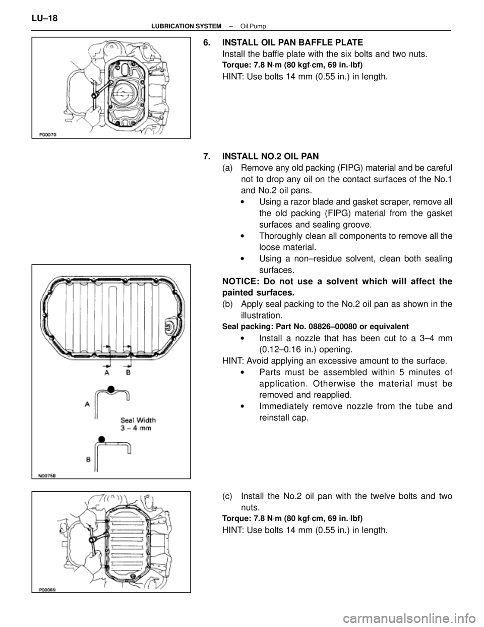
6. INSTALL OIL PAN BAFFLE PLATEInstall the baffle plate with the six bolts and two nuts.
Torque: 7.8 N Vm (80 kgf Vcm, 69 in. Vlbf)
HINT: Use bolts 14 mm (0.55 in.) in length.
7. INSTALL NO.2 OIL PAN (a) Remove any old packing (FIPG) material and be carefulnot to drop any oil on the contact surfaces of the No.1
and No.2 oil pans.
w Using a razor blade and gasket scraper, remove all
the old packing (FIPG) material from the gasket
surfaces and sealing groove.
w Thoroughly clean all components to remove all the
loose material.
w Using a non±residue solvent, clean both sealing
surfaces.
NOTICE: Do not use a solvent which will affect the
painted surfaces.
(b) Apply seal packing to the No.2 oil pan as shown in the illustration.
Seal packing: Part No. 08826±00080 or equivalent
w Install a nozzle that has been cut to a 3±4 mm
(0.12±0.16 in.) opening.
HINT: Avoid applying an excessive amount to the surface. w Parts must be assembled within 5 minutes of
application. Otherwise the material must be
removed and reapplied.
w Immediately remove nozzle from the tube and
reinstall cap.
(c) Install the No.2 oil pan with the twelve bolts and two nuts.
Torque: 7.8 N Vm (80 kgf Vcm, 69 in. Vlbf)
HINT: Use bolts 14 mm (0.55 in.) in length.
LU±18
±
LUBRICATION SYSTEM Oil Pump
WhereEverybodyKnowsYourName
Page 2574 of 4087
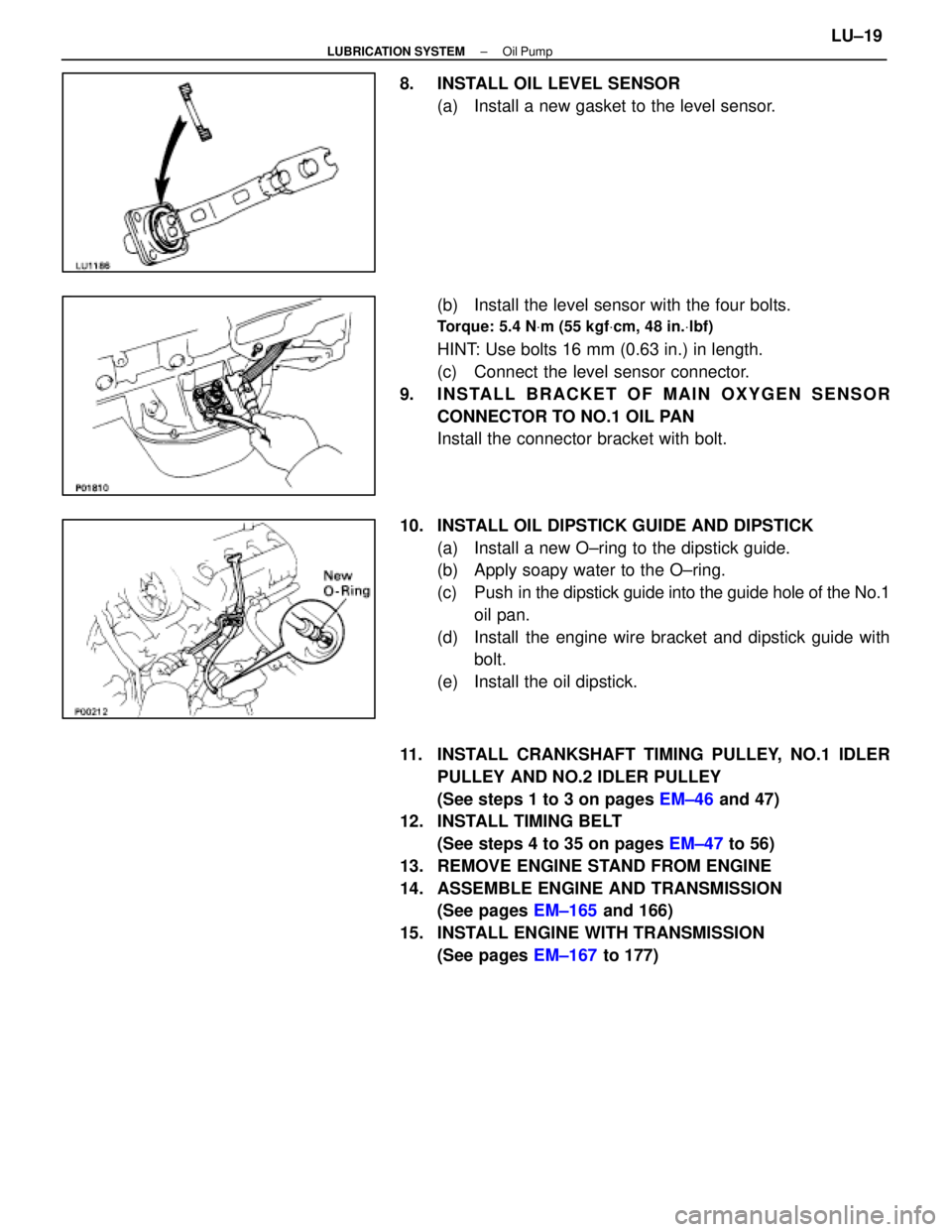
8. INSTALL OIL LEVEL SENSOR(a) Install a new gasket to the level sensor.
(b) Install the level sensor with the four bolts.
Torque: 5.4 N Vm (55 kgf Vcm, 48 in. Vlbf)
HINT: Use bolts 16 mm (0.63 in.) in length.
(c) Connect the level sensor connector.
9. INSTALL BRACKET OF MAIN OXYGEN SENSOR CONNECTOR TO NO.1 OIL PAN
Install the connector bracket with bolt.
10. INSTALL OIL DIPSTICK GUIDE AND DIPSTICK (a) Install a new O±ring to the dipstick guide.
(b) Apply soapy water to the O±ring.
(c) Push in the dipstick guide into the guide hole of the No.1
oil pan.
(d) Install the engine wire bracket and dipstick guide with bolt.
(e) Install the oil dipstick.
11. INSTALL CRANKSHAFT TIMING PULLEY, NO.1 IDLER PULLEY AND NO.2 IDLER PULLEY
(See steps 1 to 3 on pages EM±46 and 47)
12. INSTALL TIMING BELT
(See steps 4 to 35 on pages EM±47 to 56)
13. REMOVE ENGINE STAND FROM ENGINE
14. ASSEMBLE ENGINE AND TRANSMISSION (See pages EM±165 and 166)
15. INSTALL ENGINE WITH TRANSMISSION (See pages EM±167 to 177)
±
LUBRICATION SYSTEM Oil PumpLU±19
WhereEverybodyKnowsYourName
Page 2593 of 4087
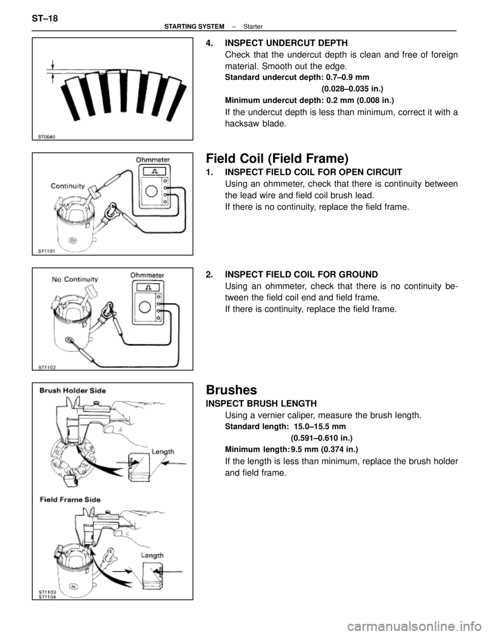
4. INSPECT UNDERCUT DEPTHCheck that the undercut depth is clean and free of foreign
material. Smooth out the edge.
Standard undercut depth: 0.7±0.9 mm
(0.028±0.035 in.)
Minimum undercut depth: 0.2 mm (0.008 in.)
If the undercut depth is less than minimum, correct it with a
hacksaw blade.
Field Coil (Field Frame)
1. INSPECT FIELD COIL FOR OPEN CIRCUIT Using an ohmmeter, check that there is continuity between
the lead wire and field coil brush lead.
If there is no continuity, replace the field frame.
2. INSPECT FIELD COIL FOR GROUND Using an ohmmeter, check that there is no continuity be-
tween the field coil end and field frame.
If there is continuity, replace the field frame.
Brushes
INSPECT BRUSH LENGTHUsing a vernier caliper, measure the brush length.
Standard length: 15.0±15.5 mm
(0.591±0.610 in.)
Minimum length: 9.5 mm (0.374 in.)
If the length is less than minimum, replace the brush holder
and field frame.
ST±18
±
STARTING SYSTEM Starter
WhereEverybodyKnowsYourName
Page 2601 of 4087
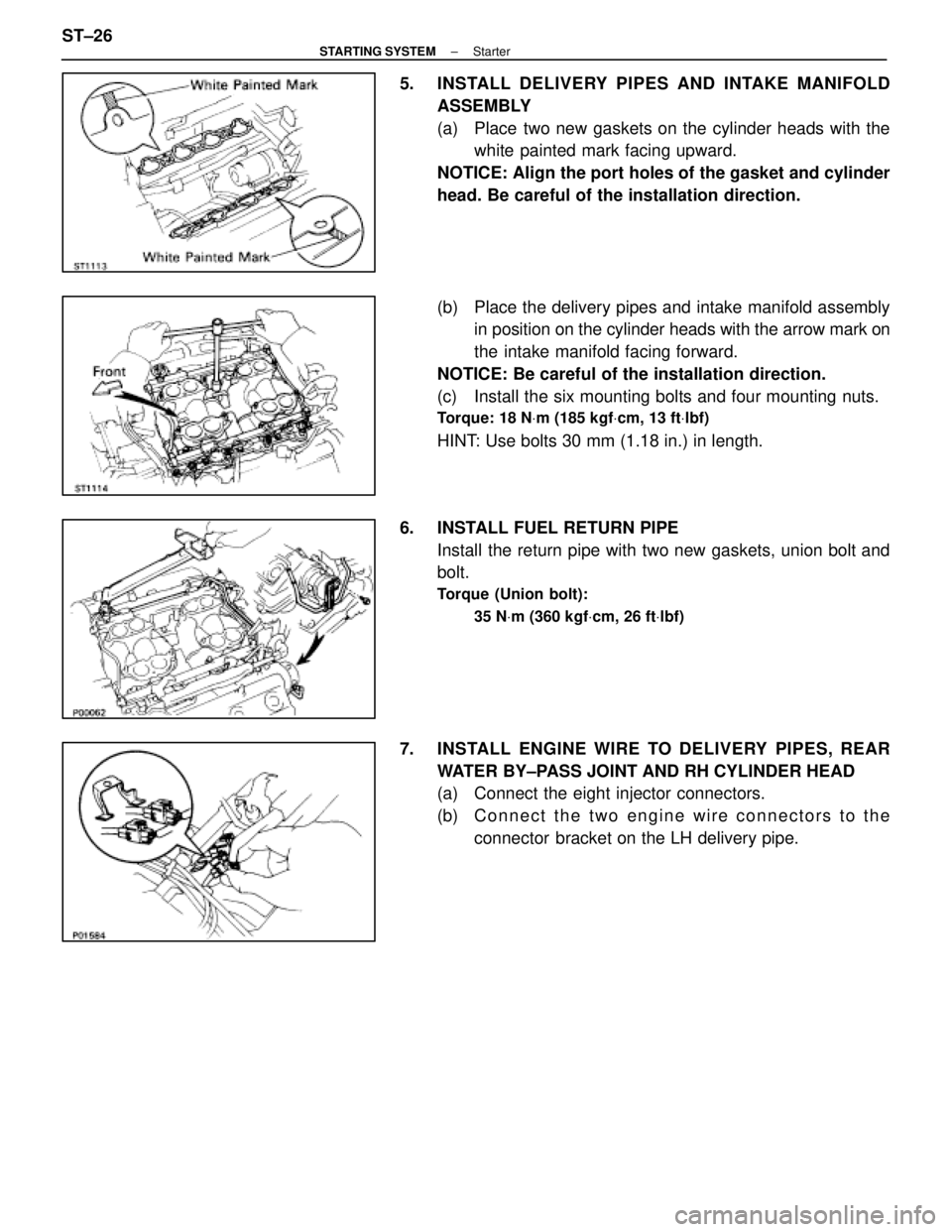
5. INSTALL DELIVERY PIPES AND INTAKE MANIFOLDASSEMBLY
(a) Place two new gaskets on the cylinder heads with thewhite painted mark facing upward.
NOTICE: Align the port holes of the gasket and cylinder
head. Be careful of the installation direction.
(b) Place the delivery pipes and intake manifold assembly in position on the cylinder heads with the arrow mark on
the intake manifold facing forward.
NOTICE: Be careful of the installation direction.
(c) Install the six mounting bolts and four mounting nuts.
Torque: 18 N Vm (185 kgf Vcm, 13 ft Vlbf)
HINT: Use bolts 30 mm (1.18 in.) in length.
6. INSTALL FUEL RETURN PIPE Install the return pipe with two new gaskets, union bolt and
bolt.
Torque (Union bolt):
35 NVm (360 kgf Vcm, 26 ft Vlbf)
7. INSTALL ENGINE WIRE TO DELIVERY PIPES, REAR
WATER BY±PASS JOINT AND RH CYLINDER HEAD
(a) Connect the eight injector connectors.
(b) C onnect the two engine wire connectors to the
connector bracket on the LH delivery pipe.
ST±26
±
STARTING SYSTEM Starter
WhereEverybodyKnowsYourName
Page 2602 of 4087
(c) Install the engine wire to the RH cylinder head with thetwo bolts.
(d) Install the engine wire to the rear water by±pass joint with the two bolts.
(e) Install the engine wire to the delivery pipes with the four bolts.
8. INSTALL ENGINE WIRE TO INTAKE MANIFOLD Install the engine wire with the two bolts.
9. TEMPORARILY INSTALL EGR PIPE TO RH CYLINDER HEAD
Temporarily install the EGR pipe with the bolt.
10. CONNECT FUEL RETURN HOSE TO FUEL RETURN PIPE
11. CONNECT FUEL INLET HOSE TO LH DELIVERY PIPE Using SST, connect the inlet hose with two new gaskets and
pulsation damper.
SST 09612±24014 (09617±24011)
Torque: 39 N Vm (400 kgf Vcm, 29 ft Vlbf)
33 N Vm (340 kgf Vcm, 24 ft Vlbf) for SST
HINT: Use a torque wrench with a fulcrum length of 30 cm
(11.81 in.).
±
STARTING SYSTEM StarterST±27
WhereEverybodyKnowsYourName