Page 3336 of 4087

(e) The drive shaft is designed to move + 20 mm from the normalposition.
Drive shaft standard length:
RH 598.5 mm (23.563 in.)
LH 553.5 mm (21.791 in.)
8. INSTALL NEW END COVER
(a) Pack grease into the end cover.
Grease capacity:50±55 g (0.11±0.12 lb, 1.8±1.9 oz.)
(b) Remove grease from the surface of the inboard joint facingthe cover.
(c) Glue on a new gasket, with the side with adhesive on it facing
toward the outer race side of the inboard joint.
(d) Align the bolt holes of the cover with those of the inboard joint.
(e) Install the 6 hexagon bolts and washer from the end cover side.
(f) Install the 6 nuts to the boot side.
(g) Using a 10 mm hexagon wrench, tighten the bolts. Do this in
the order shown, and repeat several times.
(h) Check that the claw of the end cover touches the inboard joint.
9. CHECK DRIVE SHAFT Check that operation of the joint is smooth within the sliding
region in the axial direction.
HINT: If a large angle is used for the cross±groove type joint,
the joint will feel like it is catching, but this does not indicate
an abnormality.
±
SUSPENSION AND AXLE REAR DRIVE SHAFTSA±73
WhereEverybodyKnowsYourName
Page 3362 of 4087

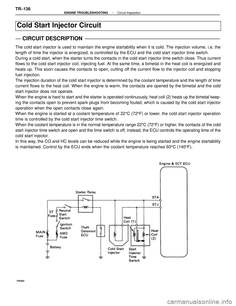
Cold Start Injector Circuit
CIRCUIT DESCRIPTION
The cold start injector is used to maintain the engine startability when it\
is cold. The injection volume, i,e, the
length of time the injector is energized, is controlled by the ECU and t\
he cold start injector time switch.
During a cold start, when the starter turns the contacts in the cold start inj\
ector time switch close. Thus current
flows to the cold start injector coil, injecting fuel. At the same time, a bi\
metal in the heat coil is energized and
heats up. This soon causes the contacts to open, cutting off the current flow to the injector coil and stopping
fuel injection.
The injection duration of the cold start injector is determined by the cool\
ant temperature and the length of time
current flows to the heat coil. When the engine is warm, the contacts are opened by the bimetal and the cold
start injector does not operate.
When the engine is hard to start and the starter is operated continuously, heat coil (2) heats up the bimetal keep-
ing the contacts open to prevent spark plugs from becoming fouled, which is\
caused by the cold start injector
operation when the open contacts close again.
When the engine is started at a coolant temperature of 225C (72 5F) or lower, the cold start injector operation
time is controlled by the cold start injector time switch.
When the coolant temperature is in the normal temperature range 22 5C (72 5F) or higher, the contacts of the cold
start injector time switch are open and the time switch is off, instead, the ECU controls the operating time of the
cold start injector.
In this way, the CO and HC levels can be reduced while the engine is being started \
and the engine startability
is maintained. Control by the ECU ends when the coolant temperature reac\
hes 60 5C (140 5F).
TR±136±
ENGINE TROUBLESHOOTING Circuit Inspection
WhereEverybodyKnowsYourName
Page 3574 of 4087

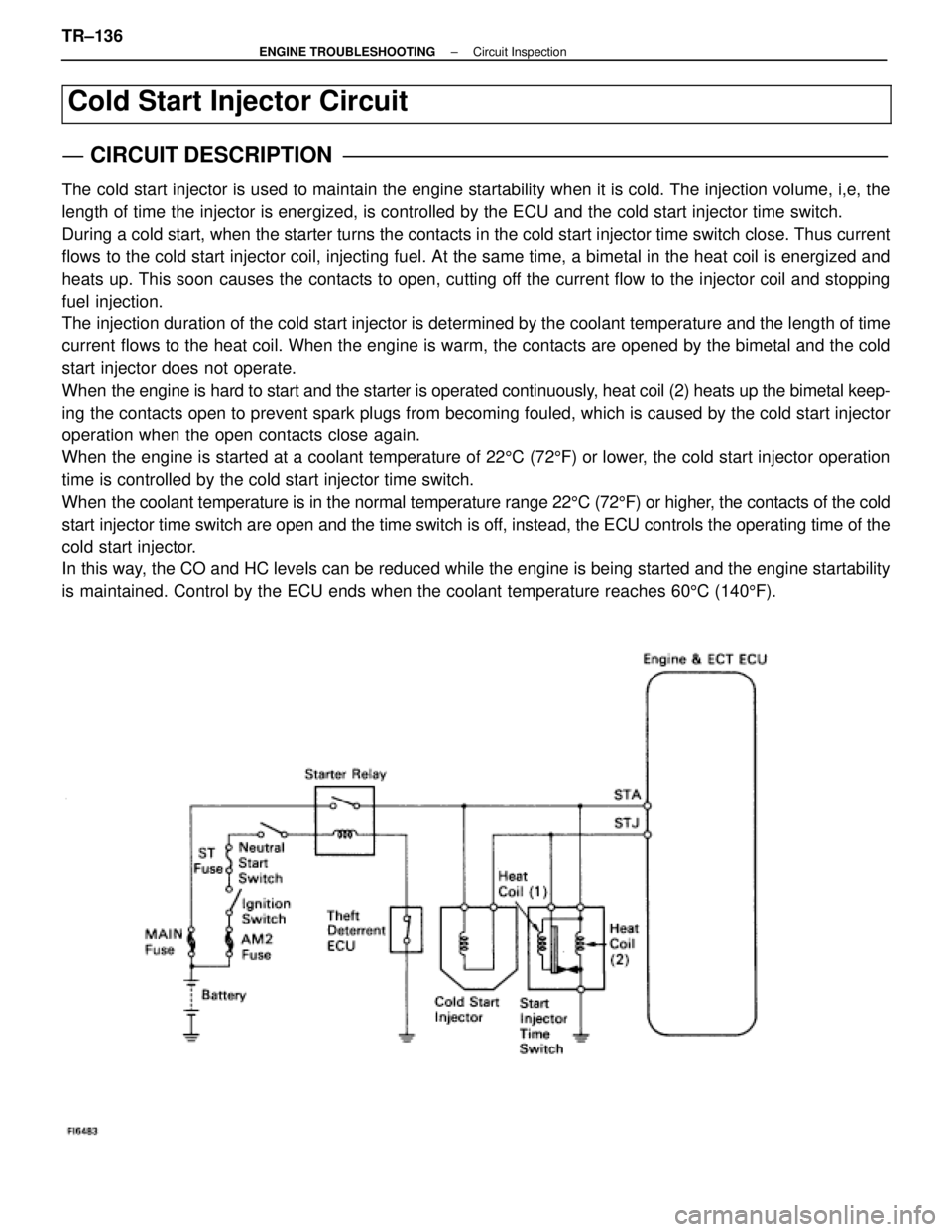
Cold Start Injector Circuit
CIRCUIT DESCRIPTION
The cold start injector is used to maintain the engine startability when it\
is cold. The injection volume, i,e, the
length of time the injector is energized, is controlled by the ECU and t\
he cold start injector time switch.
During a cold start, when the starter turns the contacts in the cold start inj\
ector time switch close. Thus current
flows to the cold start injector coil, injecting fuel. At the same time, a bi\
metal in the heat coil is energized and
heats up. This soon causes the contacts to open, cutting off the current flow to the injector coil and stopping
fuel injection.
The injection duration of the cold start injector is determined by the cool\
ant temperature and the length of time
current flows to the heat coil. When the engine is warm, the contacts are opened by the bimetal and the cold
start injector does not operate.
When the engine is hard to start and the starter is operated continuously, heat coil (2) heats up the bimetal keep-
ing the contacts open to prevent spark plugs from becoming fouled, which is\
caused by the cold start injector
operation when the open contacts close again.
When the engine is started at a coolant temperature of 225C (72 5F) or lower, the cold start injector operation
time is controlled by the cold start injector time switch.
When the coolant temperature is in the normal temperature range 22 5C (72 5F) or higher, the contacts of the cold
start injector time switch are open and the time switch is off, instead, the ECU controls the operating time of the
cold start injector.
In this way, the CO and HC levels can be reduced while the engine is being started \
and the engine startability
is maintained. Control by the ECU ends when the coolant temperature reac\
hes 60 5C (140 5F).
TR±136±
ENGINE TROUBLESHOOTING Circuit Inspection
WhereEverybodyKnowsYourName
Page 3902 of 4087

67
2. CONTROL SYSTEM
*EFI (ELECTRONIC FUEL INJECTION) SYSTEM
THE EFI SYSTEM MONITORS THE ENGINE CONDITION THROUGH THE SIGNALS INPUT FROM EACH SENSOR (IN\
PUT SIGNALS
FROM (1) TO (13) ETC.) TO THE ECU. THE BEST FUEL INJECTION TIMING IS DECIDED BASED ON THIS DATA AND THE PROGRAM
MEMORIZED BY THE ECU, AND THE CONTROL SIGNAL IS OUTPUT TO TERMINALS #10, #20, #30, #40, #50 AND #60 OF THE ECU TO
OPERATE THE INJECTOR. (INJECT THE FUEL). THE EFI SYSTEM PRODUCES CONTROL OF FUEL INJECTION OPERATION BY THE
ECU IN RESPONSE TO THE DRIVING CONDITIONS.
* ESA (ELECTRONIC SPARK ADVANCE) SYSTEM
THE ESA SYSTEM MONITORS THE ENGINE CONDITION THROUGH THE SIGNALS INPUT TO THE ECU FROM EACH SENSOR (INPUT
SIGNALS FROM (1), (2), (4) TO (13) ETC.). THE BEST IGNITION TIMING IS DECIDED ACCORDING TO THIS DATA AND THE
MEMORIZED DATA IN THE ECU AND THE CONTROL SIGNAL IS OUTPUT TO TERMINAL IGT THIS SIGNAL CONTROLS THE IGNITER
TO PROVIDE THE BEST IGNITION TIMING FOR THE DRIVING CONDITIONS.
* OXYGEN SENSOR HEATER CONTROL SYSTEM (USA SPEC.)
THE OXYGEN SENSOR HEATER CONTROL SYSTEM TURNS THE HEATER ON WHEN THE INTAKE AIR VOLUME IS LOW (TEMP. OF
EXHAUST EMISSIONS IS LOW), AND WARMS UP THE OXYGEN SENSOR TO IMPROVE DETECTION PERFORMANCE OF THE
SENSOR.
THE ECU EVALUATES THE SIGNALS FROM EACH SENSOR (INPUT SIGNALS FROM (1), (2), (4)\
, (9) TO (11) ETC.,) AND OUTPUTS
CURRENT TO TERMINAL HT TO CONTROL THE HEATER.
* ISC (IDLE SPEED CONTROL) SYSTEM
THE ISC SYSTEM (STEP MOTOR TYPE) INCREASES THE RPM AND PROVIDES IDLING STABILITY FOR FAST IDLE±UP WHEN THE
ENGINE IS COLD, AND WHEN THE IDLE SPEED HAS DROPPED DUE TO ELECTRICAL LOAD AND SO ON. THE ECU EVALUATES
THE SIGNALS FROM EACH SENSOR (INPUT SIGNALS FROM (1), (4), (5), (8)\
, (9), (11) ETC.), OUTPUTS CURRENT TO TERMINAL ISC1,
ISC2, ISC3 AND ISC4 TO CONTROL ISC VALVE.
* EGR CONTROL SYSTEM
THE EGR CONTROL SYSTEM DETECTS THE SIGNAL FROM EACH SENSOR (INPUT SIGNALS \
FROM (1), (4), (9), (10) ETC.), AND
OUTPUTS CURRENT TO TERMINAL EGR TO CONTROL THE EGR VALVE.
* FUEL PUMP CONTROL SYSTEM
THE COMPUTER OUTPUTS CURRENT TO TERMINAL FPC AND CONTROLS THE FUEL PUMP ECU AND FUEL PUMP DRIVE SPEED
IN RESPONSE TO CONDITIONS.
* ACIS (ACOUSTIC CONTROL INDUCTION SYSTEM)
ACIS INCLUDES A VALVE IN THE BULKHEAD SEPARATING THE SURGE TANK INTO TWO PARTS. THIS VALE IS OPENED AND
CLOSED IN ACCORDANCE WITH THE DRIVING CONDITIONS TO CONTROL THE INTAKE MANIFOLD LENGTH IN TWO STAGES FOR
INCREASED ENGINE OUTPUT IN ALL RANGES FROM LOW TO HIGH SPEEDS.
THE ECU JUDGES THE VEHICLE SPEED BY THE SIGNALS ((4), (5)) FROM EACH \
SENSOR AND OUTPUTS SIGNALS TO THE
TERMINAL ACIS TO CONTROL THE VSV (FOR OPENING AND CLOSING THE INTAKE CONTROL VALVE).
3. DIAGNOSIS SYSTEM
WITH THE DIAGNOSIS SYSTEM, WHEN THERE IS A MALFUNCTION IN THE ECU SIGNAL\
SYSTEM, THE MALFUNCTIONING SYSTEM IS
RECORDED IN THE MEMORY. THE MALFUNCTIONING SYSTEM CAN BE FOUND BY READING THE CODE DISPLAYED BY THE
CHECKING ENGINE WARNING LIGHT.
4. FAIL±SAFE SYSTEM
WHEN A MALFUNCTION HAS OCCURRED IN ANY SYSTEM, IF THERE IS A POSSIBILITY OF \
ENGINE TROUBLE BEING CAUSED BY
CONTINUED CONTROL BASED ON THE SIGNALS FROM THAT SYSTEM, THE FAIL±SAFE SYSTEM EITHER CONTROLS THE SYSTEM
BY USING DATA (STANDARD VALUES) RECORDED IN THE ECU MEMORY OR ELSE STOPS THE ENGINE.
NOTE: THE SPECIFICATION DESCRIPTIONS ªUSA SPEC.º AND ªEXC. USA SPEC.º USED IN THIS SECTION INDICATE THE
FOLLOWING SPECIFICATIONS.
USA SPEC. : USA (50 STATES) SPECIFICATIONS
EXC. USA SPEC. : USA (EXCEPT CALIFORNIA) AND CANADIAN SPECIFICATIONS.
WhereEverybodyKnowsYourName