Page 2603 of 4087
12. INSTALL AIR INTAKE CHAMBER(a) Place four new gaskets and the air intake chamber onthe intake manifold.
(b) Temporarily install a new gasket and the EGR pipe to air
intake chamber with the two bolts.
(c) (Exc. USA Spec.) Install the connector bracket to check (ºDIAGNOSISº)
connector.
(d) Install the air intake chamber and following parts with the four bolts and eight nuts:
(1) Check (ºDIAGNOSISº) connector
(2) A/T throttle cable bracket
(3) VSV for fuel pressure control system
(4) VSV for EGR system
Torque: 18 N Vm (185 kgf Vcm, 13 ft Vlbf)
HINT: Use bolts 40 mm (1.57 in.) of length.
ST±28
±
STARTING SYSTEM Starter
WhereEverybodyKnowsYourName
Page 2605 of 4087
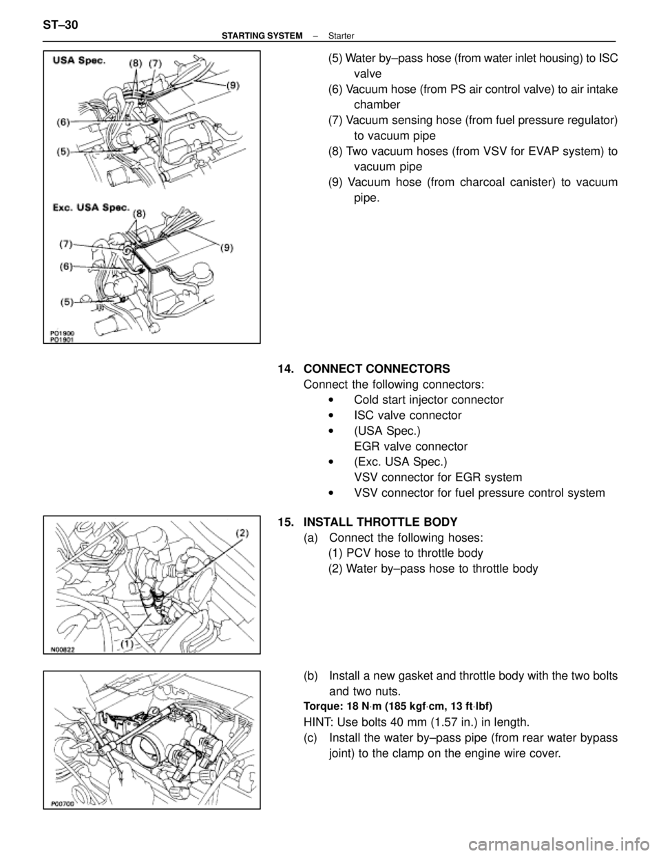
(5) Water by±pass hose (from water inlet housing) to ISC
valve
(6) Vacuum hose (from PS air control valve) to air intake chamber
(7) Vacuum sensing hose (from fuel pressure regulator) to vacuum pipe
(8) Two vacuum hoses (from VSV for EVAP system) to vacuum pipe
(9) Vacuum hose (from charcoal canister) to vacuum pipe.
14. CONNECT CONNECTORS Connect the following connectors:w Cold start injector connector
w ISC valve connector
w (USA Spec.)
EGR valve connector
w (Exc. USA Spec.)
VSV connector for EGR system
w VSV connector for fuel pressure control system
15. INSTALL THROTTLE BODY (a) Connect the following hoses:(1) PCV hose to throttle body
(2) Water by±pass hose to throttle body
(b) Install a new gasket and throttle body with the two bolts and two nuts.
Torque: 18 N Vm (185 kgf Vcm, 13 ft Vlbf)
HINT: Use bolts 40 mm (1.57 in.) in length.
(c) Install the water by±pass pipe (from rear water bypass
joint) to the clamp on the engine wire cover.
ST±30
±
STARTING SYSTEM Starter
WhereEverybodyKnowsYourName
Page 2611 of 4087

SERVICE SPECIFICATIONS
SERVICE DATA
StarterRated voltage and output power12 V 2.0 kW
No±load characteristicCurrent 120 A or less at 11.5 V
rpm 3,300 rpm or more at 11.5 V
Brush lengthSTD 15.0±15.5 mm0.591±0.610 in.
Limit 9.5 mm0.374 in.
CommutatorOuter diameter STD 35.0 mm1.378 in.
Limit 34.0 mm1.339 in.
Undercut depth STD 0.7±0.9 mm0.028±0.035 in.
Limit 0.2 mm0.008 in.
Circle runout Limit 0.05 mm0.0020 in.
Spring installed load26±32 N
(2.7±3.3 kgf, 6.0±7.3 lbf)
TORQUE SPECIFICATIONS
Part tightenedNVmkgf Vcmft Vlbf
Starter X Cylinder block3940029
Rear water by±pass joint X Cylinder head18185 13
Water by±pass pipe X Cylinder block18185 13
Intake manifold X Cylinder head18185 13
Fuel return pipe X Fuel pressure regulator35360 26
Fuel inlet hose X LH delivery pipe39400 29
for SST 33340 24
Air intake chamber X Intake manifold18185 13
EGR pipe X Air intake chamber18185 13
EGR pipe X RH cylinder head18185 13
Cold start injector tube X RH delivery pipe15150 11
Throttle body X Air intake chamber1818513
ST±36±
STARTING SYSTEM Service Specifications
WhereEverybodyKnowsYourName
Page 2747 of 4087
Cold Start Injector Circuit
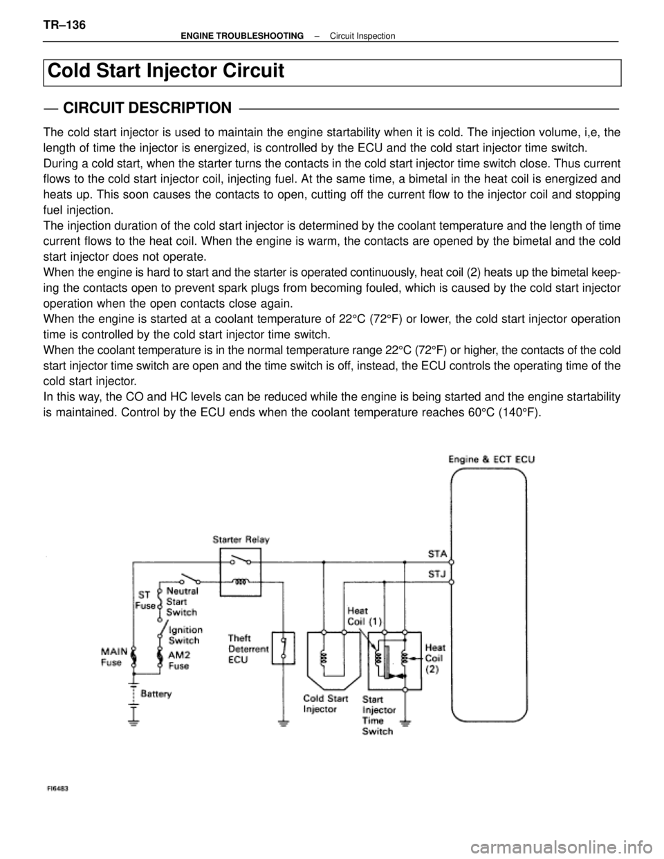
CIRCUIT DESCRIPTION
The cold start injector is used to maintain the engine startability when it\
is cold. The injection volume, i,e, the
length of time the injector is energized, is controlled by the ECU and t\
he cold start injector time switch.
During a cold start, when the starter turns the contacts in the cold start inj\
ector time switch close. Thus current
flows to the cold start injector coil, injecting fuel. At the same time, a bi\
metal in the heat coil is energized and
heats up. This soon causes the contacts to open, cutting off the current flow to the injector coil and stopping
fuel injection.
The injection duration of the cold start injector is determined by the cool\
ant temperature and the length of time
current flows to the heat coil. When the engine is warm, the contacts are opened by the bimetal and the cold
start injector does not operate.
When the engine is hard to start and the starter is operated continuously, heat coil (2) heats up the bimetal keep-
ing the contacts open to prevent spark plugs from becoming fouled, which is\
caused by the cold start injector
operation when the open contacts close again.
When the engine is started at a coolant temperature of 225C (72 5F) or lower, the cold start injector operation
time is controlled by the cold start injector time switch.
When the coolant temperature is in the normal temperature range 22 5C (72 5F) or higher, the contacts of the cold
start injector time switch are open and the time switch is off, instead, the ECU controls the operating time of the
cold start injector.
In this way, the CO and HC levels can be reduced while the engine is being started \
and the engine startability
is maintained. Control by the ECU ends when the coolant temperature reac\
hes 60 5C (140 5F).
TR±136±
ENGINE TROUBLESHOOTING Circuit Inspection
WhereEverybodyKnowsYourName
Page 2778 of 4087
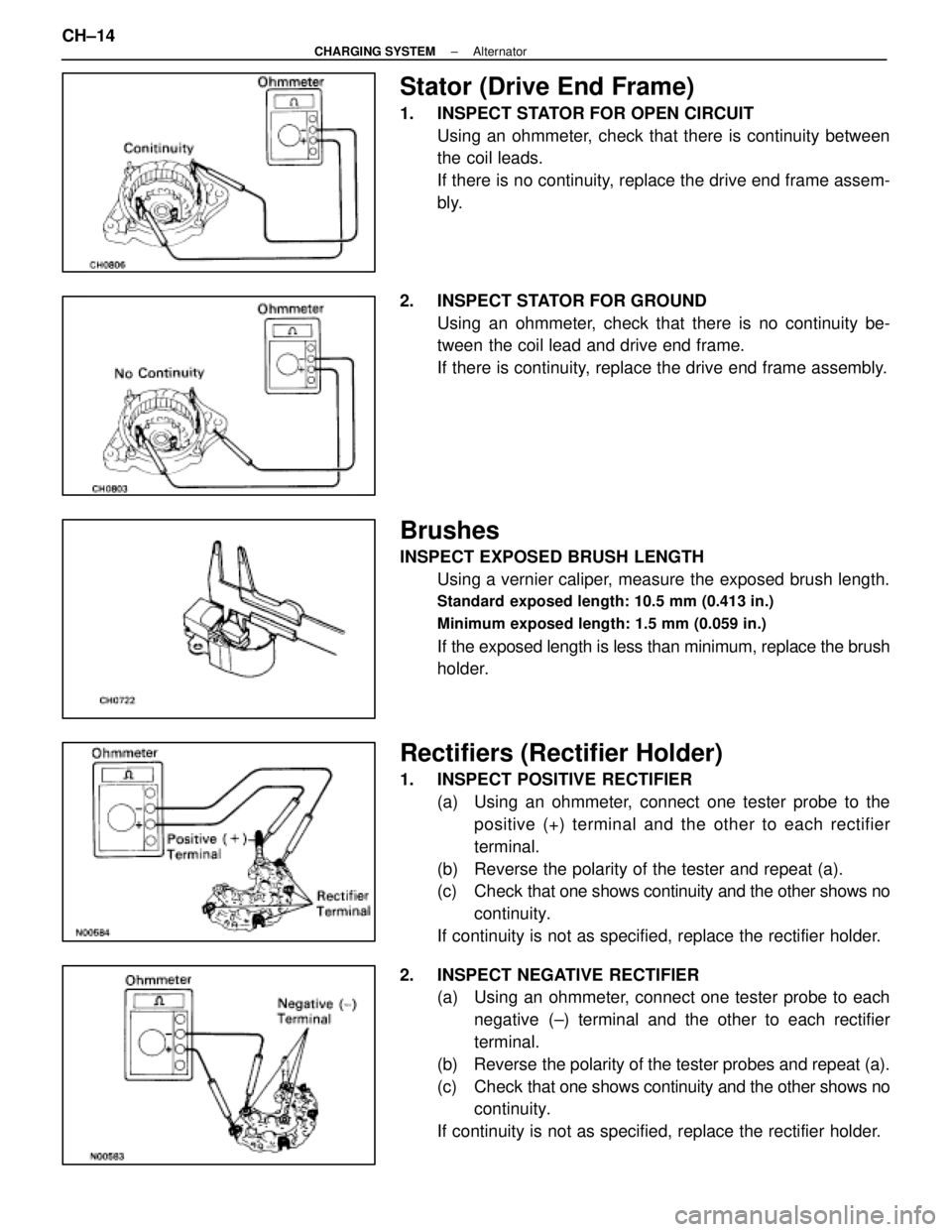
Stator (Drive End Frame)
1. INSPECT STATOR FOR OPEN CIRCUITUsing an ohmmeter, check that there is continuity between
the coil leads.
If there is no continuity, replace the drive end frame assem-
bly.
2. INSPECT STATOR FOR GROUND Using an ohmmeter, check that there is no continuity be-
tween the coil lead and drive end frame.
If there is continuity, replace the drive end frame assembly.
Brushes
INSPECT EXPOSED BRUSH LENGTHUsing a vernier caliper, measure the exposed brush length.
Standard exposed length: 10.5 mm (0.413 in.)
Minimum exposed length: 1.5 mm (0.059 in.)
If the exposed length is less than minimum, replace the brush
holder.
Rectifiers (Rectifier Holder)
1. INSPECT POSITIVE RECTIFIER(a) Using an ohmmeter, connect one tester probe to thepositive (+) terminal and the other to each rectifier
terminal.
(b) Reverse the polarity of the tester and repeat (a).
(c) Check that one shows continuity and the other shows no
continuity.
If continuity is not as specified, replace the rectifier holder.
2. INSPECT NEGATIVE RECTIFIER (a) Using an ohmmeter, connect one tester probe to each
negative (±) terminal and the other to each rectifier
terminal.
(b) Reverse the polarity of the tester probes and repeat (a).
(c) Check that one shows continuity and the other shows no
continuity.
If continuity is not as specified, replace the rectifier holder.
CH±14
±
CHARGING SYSTEM Alternator
WhereEverybodyKnowsYourName
Page 2785 of 4087
SERVICE SPECIFICATIONS
SERVICE DATA
BatterySpecific gravity1.27±1.29
(when fully charged at 205C (68 5F))
AlternatorRated output12 V±100 A
Rotor coil resistance2.8±3.0 �
Slip ring diameterSTD 14.2±14.4 mm0.559±0567 in.
Limit 12.8 mm0.504 in.
Brush exposed lengthSTD 10.5 mm0.413 in.
Limit 1.5 mm0.059 in.
AlternatorRegulating voltageat 255C (77 5F)13.9±15.1 V
regulatorat 115 5C (239 5F)13.5±14.3 V
TORQUE SPECIFICATIONS
Part tightenedN Vmkgf Vcmft Vlbf
Alternator pulley X Rotor11 01,12581
Alternator X Alternator bracket37380 27
Alternator X Cylinder block3738027
±
CHARGING SYSTEM Service SpecificationsCH±21
WhereEverybodyKnowsYourName
Page 2796 of 4087
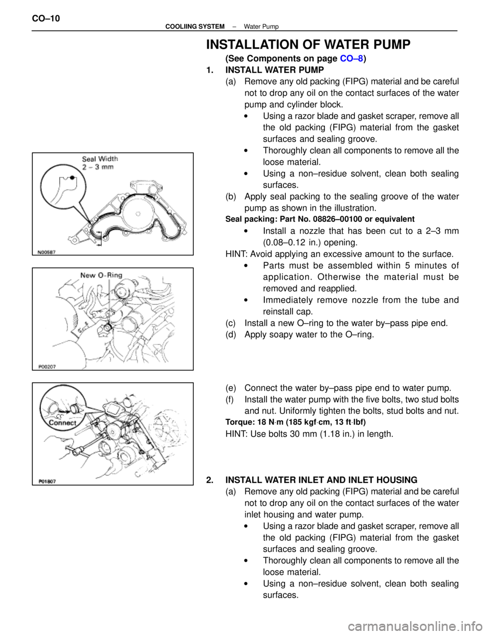
INSTALLATION OF WATER PUMP
(See Components on page CO±8)
1. INSTALL WATER PUMP (a) Remove any old packing (FIPG) material and be careful
not to drop any oil on the contact surfaces of the water
pump and cylinder block.
w Using a razor blade and gasket scraper, remove all
the old packing (FIPG) material from the gasket
surfaces and sealing groove.
w Thoroughly clean all components to remove all the
loose material.
w Using a non±residue solvent, clean both sealing
surfaces.
(b) Apply seal packing to the sealing groove of the water pump as shown in the illustration.
Seal packing: Part No. 08826±00100 or equivalent
w Install a nozzle that has been cut to a 2±3 mm
(0.08±0.12 in.) opening.
HINT: Avoid applying an excessive amount to the surface. w Parts must be assembled within 5 minutes of
application. Otherwise the material must be
removed and reapplied.
w Immediately remove nozzle from the tube and
reinstall cap.
(c) Install a new O±ring to the water by±pass pipe end.
(d) Apply soapy water to the O±ring.
(e) Connect the water by±pass pipe end to water pump.
(f) Install the water pump with the five bolts, two stud bolts and nut. Uniformly tighten the bolts, stud bolts and nut.
Torque: 18 N Vm (185 kgf Vcm, 13 ft Vlbf)
HINT: Use bolts 30 mm (1.18 in.) in length.
2. INSTALL WATER INLET AND INLET HOUSING (a) Remove any old packing (FIPG) material and be careful
not to drop any oil on the contact surfaces of the water
inlet housing and water pump.
w Using a razor blade and gasket scraper, remove all
the old packing (FIPG) material from the gasket
surfaces and sealing groove.
w Thoroughly clean all components to remove all the
loose material.
w Using a non±residue solvent, clean both sealing
surfaces.
CO±10
±
COOLIING SYSTEM Water Pump
WhereEverybodyKnowsYourName
Page 2797 of 4087
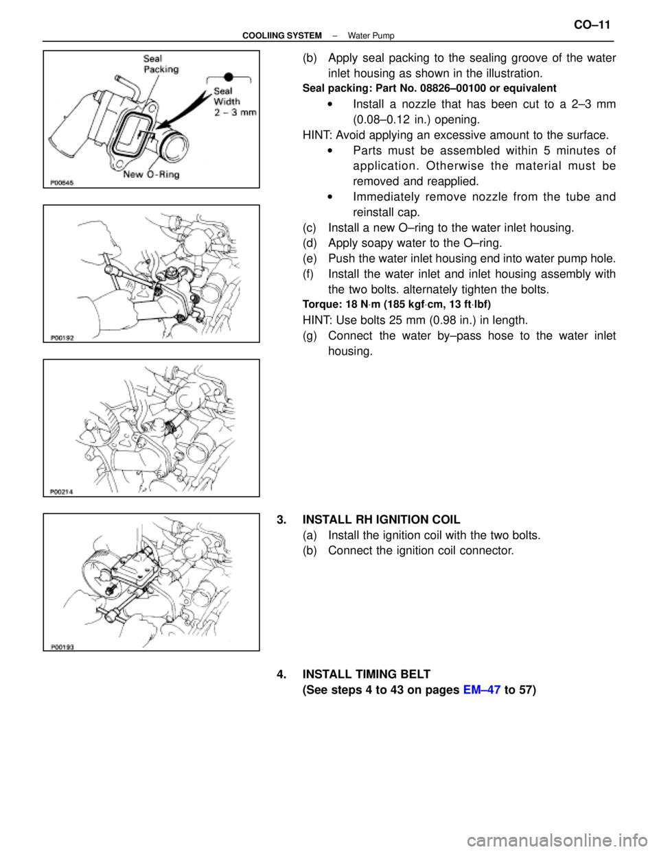
(b) Apply seal packing to the sealing groove of the waterinlet housing as shown in the illustration.
Seal packing: Part No. 08826±00100 or equivalent
w Install a nozzle that has been cut to a 2±3 mm
(0.08±0.12 in.) opening.
HINT: Avoid applying an excessive amount to the surface. w Parts must be assembled within 5 minutes of
application. Otherwise the material must be
removed and reapplied.
w Immediately remove nozzle from the tube and
reinstall cap.
(c) Install a new O±ring to the water inlet housing.
(d) Apply soapy water to the O±ring.
(e) Push the water inlet housing end into water pump hole.
(f) Install the water inlet and inlet housing assembly with the two bolts. alternately tighten the bolts.
Torque: 18 N Vm (185 kgf Vcm, 13 ft Vlbf)
HINT: Use bolts 25 mm (0.98 in.) in length.
(g) Connect the water by±pass hose to the water inlet
housing.
3. INSTALL RH IGNITION COIL (a) Install the ignition coil with the two bolts.
(b) Connect the ignition coil connector.
4. INSTALL TIMING BELT (See steps 4 to 43 on pages EM±47 to 57)
±
COOLIING SYSTEM Water PumpCO±11
WhereEverybodyKnowsYourName