Page 2248 of 4087

7. INSTALL NO.1 TIMING BELT COVER(a) Install the gasket to the timing belt cover.
(b) Install the timing belt cover with the four bolts.
8. INSTALL HYDRAULIC PUMP (a) Install the hydraulic pump and solenoid valve connectorclamp and engine speed sensor wire clamp with the two
bolts and two nuts.
Torque:
12 mm heads 16 N Vm (160 kgf Vcm, 12 ft Vlbf)
Others 30 N Vm (310 kgf Vcm, 22 ft Vlbf)
HINT: Each bolt length is indicated in the illustration.
Bolt length:
A 106 mm (4.17 in.) for 12 mm head
B 114 mm (4.49 in.) for 14 mm head
(b) Connect the solenoid valve connector.
9. INSTALL CRANKSHAFT PULLEY (a) Align the pulley set key on the crankshaft with the keygroove of the pulley.
(b) Using SST and a hammer, tap in the pulley.
SST 09223±46011
(c) Using SST, install and torque the pulley bolt.
SST 09213±70010 and 09330±00021
Torque: 245 N Vm (2,500 kgf Vcm, 181 ft Vlbf)
10. INSTALL RH CAMSHAFT TIMING PULLEY
(a) Align the knock pin on the camshaft with the knock pingroove of the timing pulley.
(b) Slide the timing pulley, facing the ºRº mark forward.
(c) Using SST, install and torque the pulley bolt.
SST 09278±54012
Torque: 108 N Vm (1,100 kgf Vcm, 80 ft Vlbf)
EM±48±
ENGINE MECHANICAL Timing Belt
WhereEverybodyKnowsYourName
Page 2252 of 4087
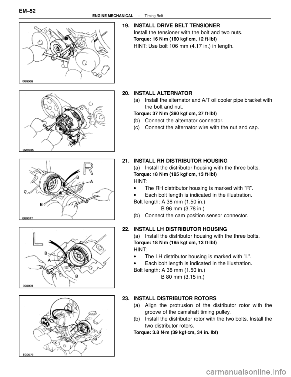
19. INSTALL DRIVE BELT TENSIONERInstall the tensioner with the bolt and two nuts.
Torque: 16 N Vm (160 kgf Vcm, 12 ft Vlbf)
HINT: Use bolt 106 mm (4.17 in.) in length.
20. INSTALL ALTERNATOR (a) Install the alternator and A/T oil cooler pipe bracket withthe bolt and nut.
Torque: 37 N Vm (380 kgf Vcm, 27 ft Vlbf)
(b) Connect the alternator connector.
(c) Connect the alternator wire with the nut and cap.
21. INSTALL RH DISTRIBUTOR HOUSING (a) Install the distributor housing with the three bolts.
Torque: 18 N Vm (185 kgf Vcm, 13 ft Vlbf)
HINT:
w The RH distributor housing is marked with ºRº.
w Each bolt length is indicated in the illustration.
Bolt length: A 38 mm (1.50 in.)
B 96 mm (3.78 in.)
(b) Connect the cam position sensor connector.
22. INSTALL LH DISTRIBUTOR HOUSING (a) Install the distributor housing with the three bolts.
Torque: 18 N Vm (185 kgf Vcm, 13 ft Vlbf)
HINT:
w The LH distributor housing is marked with ºLº.
w Each bolt length is indicated in the illustration.
Bolt length: A 38 mm (1.50 in.)
B 80 mm (3.15 in.)
23. INSTALL DISTRIBUTOR ROTORS (a) Align the protrusion of the distributor rotor with thegroove of the camshaft timing pulley.
(b) Install the distributor rotor with the two bolts. Install the two distributor rotors.
Torque: 3.8 N Vm (39 kgf Vcm, 34 in. Vlbf)
EM±52±
ENGINE MECHANICAL Timing Belt
WhereEverybodyKnowsYourName
Page 2253 of 4087
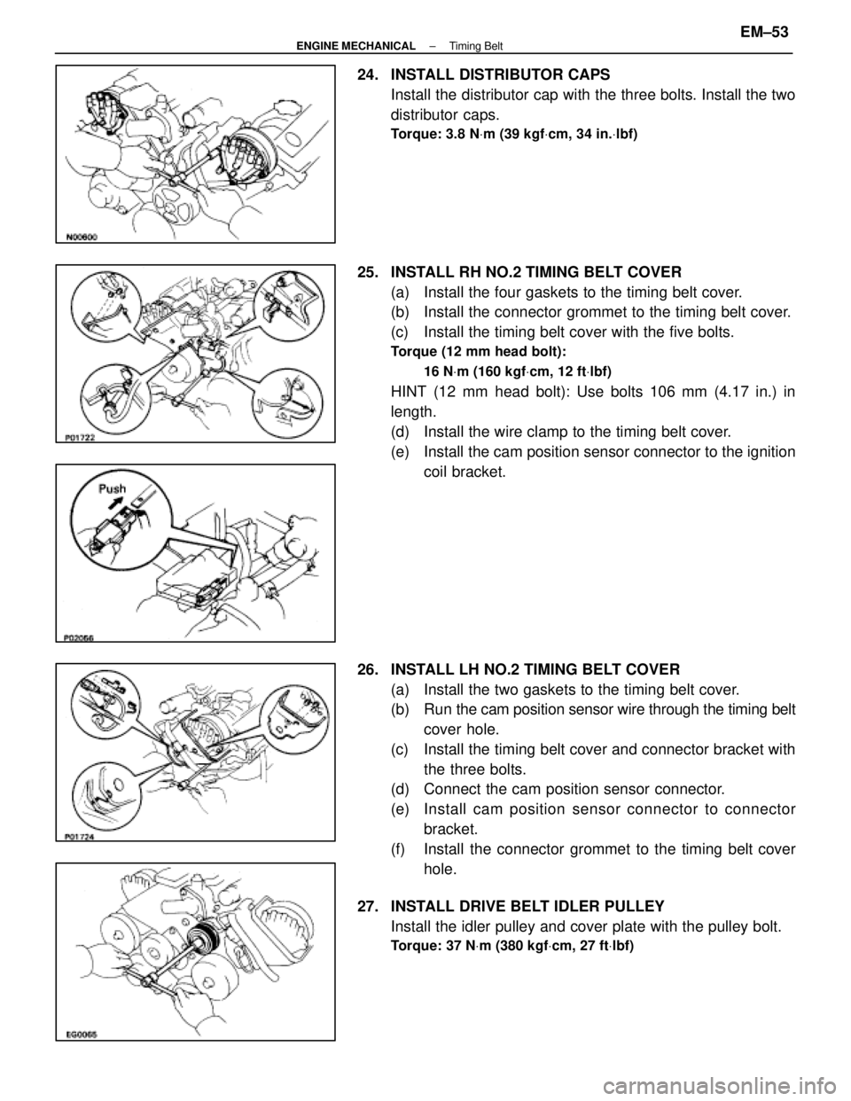
24. INSTALL DISTRIBUTOR CAPSInstall the distributor cap with the three bolts. Install the two
distributor caps.
Torque: 3.8 N Vm (39 kgf Vcm, 34 in. Vlbf)
25. INSTALL RH NO.2 TIMING BELT COVER
(a) Install the four gaskets to the timing belt cover.
(b) Install the connector grommet to the timing belt cover.
(c) Install the timing belt cover with the five bolts.
Torque (12 mm head bolt):
16 NVm (160 kgf Vcm, 12 ft Vlbf)
HINT (12 mm head bolt): Use bolts 106 mm (4.17 in.) in
length.
(d) Install the wire clamp to the timing belt cover.
(e) Install the cam position sensor connector to the ignition
coil bracket.
26. INSTALL LH NO.2 TIMING BELT COVER (a) Install the two gaskets to the timing belt cover.
(b) Run the cam po sition sensor wire through the timing belt
cover hole.
(c) Install the timing belt cover and connector bracket with the three bolts.
(d) Connect the cam position sensor connector.
(e) Install cam position sensor c onnector to connector
bracket.
(f) Install the connector grommet to the timing belt cover hole.
27. INSTALL DRIVE BELT IDLER PULLEY Install the idler pulley and cover plate with the pulley bolt.
Torque: 37 N Vm (380 kgf Vcm, 27 ft Vlbf)
±
ENGINE MECHANICAL Timing BeltEM±53
WhereEverybodyKnowsYourName
Page 2270 of 4087
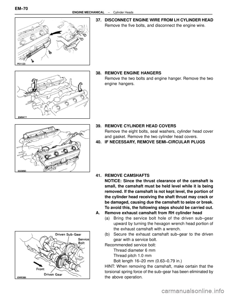
37. DISCONNECT ENGINE WIRE FROM LH CYLINDER HEAD
Remove the five bolts, and disconnect the engine wire.
38. REMOVE ENGINE HANGERS Remove the two bolts and engine hanger. Remove the two
engine hangers.
39. REMOVE CYLINDER HEAD COVERS Remove the eight bolts, seal washers, cylinder head cover
and gasket. Remove the two cylinder head covers.
40. IF NECESSARY, REMOVE SEMI±CIRCULAR PLUGS
41. REMOVE CAMSHAFTS NOTICE: Since the thrust clearance of the camshaft is
small, the camshaft must be held level while it is being
removed. If the camshaft is not kept level, the portion of
the cylinder head receiving the shaft thrust may crack or
be damaged, causing due the camshaft to seize or break.
To avoid this, the following steps should be carried out.
A. Remove exhaust camshaft from RH cylinder head
(a) Bring the service bolt hole of the driven s ub±gear
upward by turning the hexagon wrench head portion of
the exhaust camshaft with a wrench.
(b) Secure the exhaust camshaft sub±gear to the driven
gear with a service bolt.
Recommended service bolt: Thread diameter 6 mm
Thread pitch 1.0 mm
Bolt length 16±20 mm (0.63±0.79 in.)
HINT: When removing the camshaft, make certain that the
torsional spring force of the sub±gear has been eliminated by
the above operation.
EM±70
±
ENGINE MECHANICAL Cylinder Heads
WhereEverybodyKnowsYourName
Page 2272 of 4087
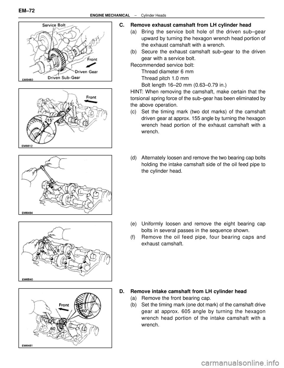
C. Remove exhaust camshaft from LH cylinder head(a) Bring the service bolt hole of the driven s ub±gear
upward by turning the hexagon wrench head portion of
the exhaust camshaft with a wrench.
(b) Secure the exhaust camshaft sub±gear to the driven gear with a service bolt.
Recommended service bolt: Thread diameter 6 mm
Thread pitch 1.0 mm
Bolt length 16±20 mm (0.63±0.79 in.)
HINT: When removing the camshaft, make certain that the
torsional spring force of the sub±gear has been eliminated by
the above operation.
(c) Set the timing mark (two dot marks) of the camshaft
driven gear at approx. 155 angle by turning the hexagon
wrench head portion of the exhaust camshaft with a
wrench.
(d) Alternately loosen and remove the two bearing cap bolts
holding the intake camshaft side of the oil feed pipe to
the cylinder head.
(e) Uniformly loosen and remove the eight bearing cap bolts in several passes in the sequence shown.
(f) Re mo ve th e oil fe e d pip e , fo u r be a rin g ca p s an d
exhaust camshaft.
D. Remove intake camshaft from LH cylinder head (a) Remove the front bearing cap.
(b) Set the timing mark ( one dot mark) of the camshaft drive
gear at approx. 605 angle by turning the hexagon
wrench head portion of the intake camshaft with a
wrench.
EM±72
±
ENGINE MECHANICAL Cylinder Heads
WhereEverybodyKnowsYourName
Page 2283 of 4087
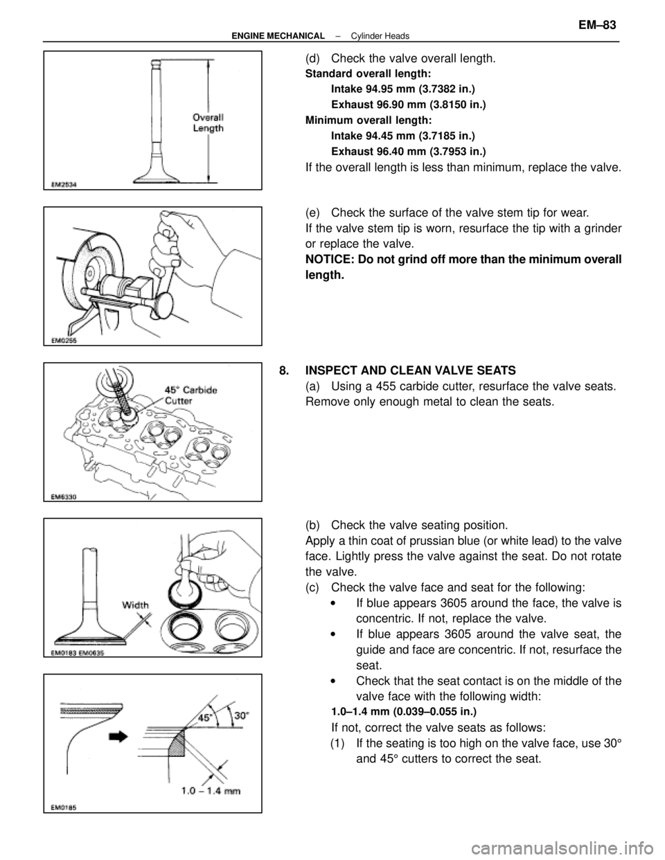
(d) Check the valve overall length.
Standard overall length:Intake 94.95 mm (3.7382 in.)
Exhaust 96.90 mm (3.8150 in.)
Minimum overall length: Intake 94.45 mm (3.7185 in.)
Exhaust 96.40 mm (3.7953 in.)
If the overall length is less than minimum, replace the valve.
(e) Check the surface of the valve stem tip for wear.
If the valve stem tip is worn, resurface the tip with a grinder
or replace the valve.
NOTICE: Do not grind off more than the minimum overall
length.
8. INSPECT AND CLEAN VALVE SEATS (a) Using a 455 carbide cutter, resurface the valve seats.
Remove only enough metal to clean the seats.
(b) Check the valve seating position.
Apply a thin coat of prussian blue (or white lead) to the valve
face. Lightly press the valve against the seat. Do not rotate
the valve.
(c) Check the valve face and seat for the following:w If blue appears 3605 around the face, the valve is
concentric. If not, replace the valve.
w If blue appears 3605 around the valve seat, the
guide and face are concentric. If not, resurface the
seat.
w Check that the seat contact is on the middle of the
valve face with the following width:
1.0±1.4 mm (0.039±0.055 in.)
If not, correct the valve seats as follows:
(1) If the seating is too high on the valve face, use 30 5
and 45 5 cutters to correct the seat.
±
ENGINE MECHANICAL Cylinder HeadsEM±83
WhereEverybodyKnowsYourName
Page 2284 of 4087
(2) If the seating is too low on the valve face, use 755
and 45 5 cutters to correct the seat.
(d) Hand±lap the valve and valve seat with an abrasive compound.
(e) After hand±lapping, clean the valve and valve seat.
9. INSPECT VALVE SPRINGS (a) Using a steel square, measure the squareness of thevalve spring.
Maximum squareness: 2.0 mm (0.079 in.)
If squareness is greater than maximum, replace the valve
spring.
(b) Using a vernier caliper, measure the free length of the
valve spring.
Free length: 43.6 mm (1.717 in.)
If the free length is not as specified, replace the valve spring.
(c) Using a spring tester, measure the tension of the valvespring at the specified installed length.
Installed tension (at 32.9 mm (1.295 in.):
186±206 N (19.0±21.0 kgf, 41.9±46.3 lbf)
If the installed tension is not as specified, replace the valve
spring.
EM±84
±
ENGINE MECHANICAL Cylinder Heads
WhereEverybodyKnowsYourName
Page 2294 of 4087
(b) Remove any old packing (FIPG) material.
(c) Apply seal packing to the bearing caps as shown.
Seal packing: Part No. 08826±00080 or equivalent
(d) (RH Cylinder Head)Install the bearing cap (mark ºI1º) in position with the ar-
row mark facing rearward.
(e) (LH Cylinder Head) Install the bearing cap (mark ºI6º) in position with the ar-
row mark facing forward.
(f) Install a new seal washer to the bearing cap bolt.
(g) Apply a light of engine oil on the threads of the bearing
cap bolt.
(h) Install the four bearing cap bolts.
Torque: 16 N Vm (160 kgf Vcm, 12 ft Vlbf)
HINT: Use silver colored bolts 38 mm (1.50 in.) in length.
6. ASSEMBLE EXHAUST CAMSHAFTS (a) Install the following parts:(1) Camshaft gear spring
(2) Camshaft sub±gear
(3) Wave washer
(b) Using snap ring pliers, install the snap ring.
(c) M ount the hexagon wrench head portion of the
camshaft in a vice.
EM±94
±
ENGINE MECHANICAL Cylinder Heads
WhereEverybodyKnowsYourName