Page 2138 of 4087
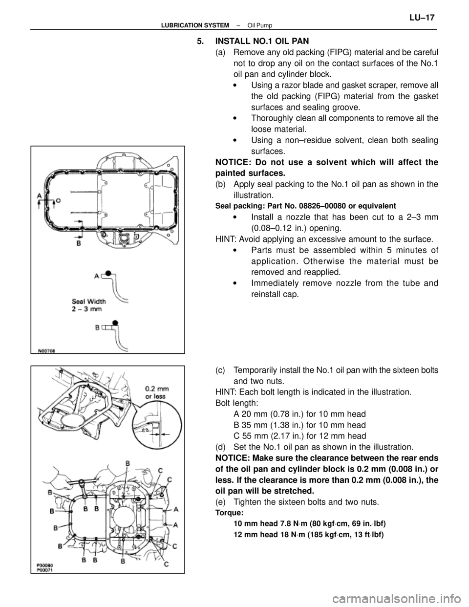
5. INSTALL NO.1 OIL PAN(a) Remove any old packing (FIPG) material and be carefulnot to drop any oil on the contact surfaces of the No.1
oil pan and cylinder block.
w Using a razor blade and gasket scraper, remove all
the old packing (FIPG) material from the gasket
surfaces and sealing groove.
w Thoroughly clean all components to remove all the
loose material.
w Using a non±residue solvent, clean both sealing
surfaces.
NOTICE: Do not use a solvent which will affect the
painted surfaces.
(b) Apply seal packing to the No.1 oil pan as shown in the illustration.
Seal packing: Part No. 08826±00080 or equivalent
w Install a nozzle that has been cut to a 2±3 mm
(0.08±0.12 in.) opening.
HINT: Avoid applying an excessive amount to the surface. w Parts must be assembled within 5 minutes of
application. Otherwise the material must be
removed and reapplied.
w Immediately remove nozzle from the tube and
reinstall cap.
(c) Temporarily install the No.1 oil pan with the sixteen bolts
and two nuts.
HINT: Each bolt length is indicated in the illustration.
Bolt length:
A 20 mm (0.78 in.) for 10 mm head
B 35 mm (1.38 in.) for 10 mm head
C 55 mm (2.17 in.) for 12 mm head
(d) Set the No.1 oil pan as shown in the illustration.
NOTICE: Make sure the clearance between the rear ends
of the oil pan and cylinder block is 0.2 mm (0.008 in.) or
less. If the clearance is more than 0.2 mm (0.008 in.), the
oil pan will be stretched.
(e) Tighten the sixteen bolts and two nuts.
Torque:
10 mm head 7.8 N Vm (80 kgf Vcm, 69 in. Vlbf)
12 mm head 18 N Vm (185 kgf Vcm, 13 ft Vlbf)
±
LUBRICATION SYSTEM Oil PumpLU±17
WhereEverybodyKnowsYourName
Page 2139 of 4087
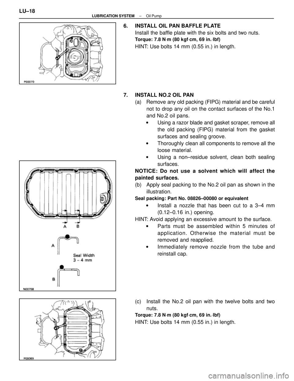
6. INSTALL OIL PAN BAFFLE PLATEInstall the baffle plate with the six bolts and two nuts.
Torque: 7.8 N Vm (80 kgf Vcm, 69 in. Vlbf)
HINT: Use bolts 14 mm (0.55 in.) in length.
7. INSTALL NO.2 OIL PAN (a) Remove any old packing (FIPG) material and be carefulnot to drop any oil on the contact surfaces of the No.1
and No.2 oil pans.
w Using a razor blade and gasket scraper, remove all
the old packing (FIPG) material from the gasket
surfaces and sealing groove.
w Thoroughly clean all components to remove all the
loose material.
w Using a non±residue solvent, clean both sealing
surfaces.
NOTICE: Do not use a solvent which will affect the
painted surfaces.
(b) Apply seal packing to the No.2 oil pan as shown in the illustration.
Seal packing: Part No. 08826±00080 or equivalent
w Install a nozzle that has been cut to a 3±4 mm
(0.12±0.16 in.) opening.
HINT: Avoid applying an excessive amount to the surface. w Parts must be assembled within 5 minutes of
application. Otherwise the material must be
removed and reapplied.
w Immediately remove nozzle from the tube and
reinstall cap.
(c) Install the No.2 oil pan with the twelve bolts and two nuts.
Torque: 7.8 N Vm (80 kgf Vcm, 69 in. Vlbf)
HINT: Use bolts 14 mm (0.55 in.) in length.
LU±18
±
LUBRICATION SYSTEM Oil Pump
WhereEverybodyKnowsYourName
Page 2140 of 4087
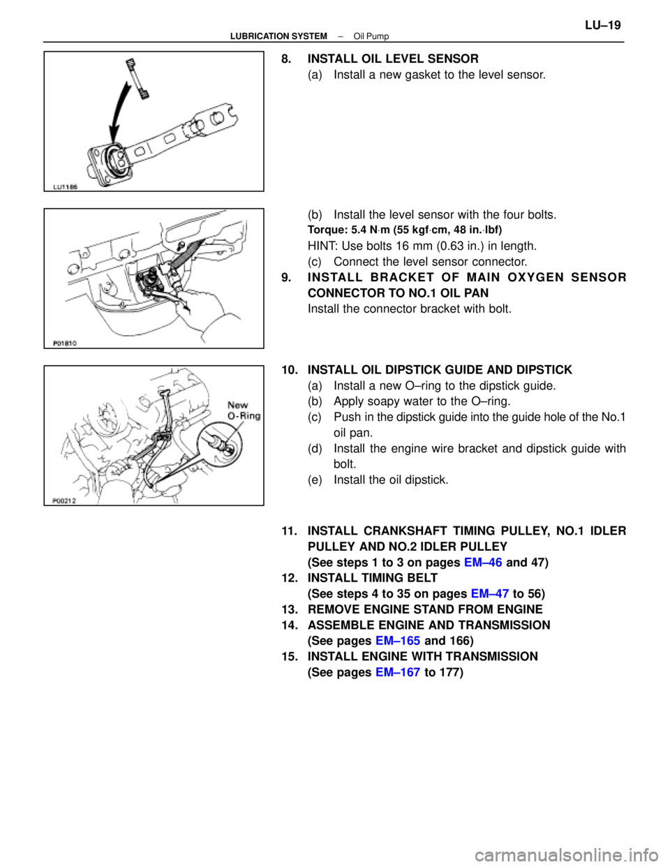
8. INSTALL OIL LEVEL SENSOR(a) Install a new gasket to the level sensor.
(b) Install the level sensor with the four bolts.
Torque: 5.4 N Vm (55 kgf Vcm, 48 in. Vlbf)
HINT: Use bolts 16 mm (0.63 in.) in length.
(c) Connect the level sensor connector.
9. INSTALL BRACKET OF MAIN OXYGEN SENSOR CONNECTOR TO NO.1 OIL PAN
Install the connector bracket with bolt.
10. INSTALL OIL DIPSTICK GUIDE AND DIPSTICK (a) Install a new O±ring to the dipstick guide.
(b) Apply soapy water to the O±ring.
(c) Push in the dipstick guide into the guide hole of the No.1
oil pan.
(d) Install the engine wire bracket and dipstick guide with bolt.
(e) Install the oil dipstick.
11. INSTALL CRANKSHAFT TIMING PULLEY, NO.1 IDLER PULLEY AND NO.2 IDLER PULLEY
(See steps 1 to 3 on pages EM±46 and 47)
12. INSTALL TIMING BELT
(See steps 4 to 35 on pages EM±47 to 56)
13. REMOVE ENGINE STAND FROM ENGINE
14. ASSEMBLE ENGINE AND TRANSMISSION (See pages EM±165 and 166)
15. INSTALL ENGINE WITH TRANSMISSION (See pages EM±167 to 177)
±
LUBRICATION SYSTEM Oil PumpLU±19
WhereEverybodyKnowsYourName
Page 2162 of 4087
MA04N±01
BRAKES
13. INSPECT BRAKE LINE PIPES AND HOSESHINT: Check in a well lighted area. Check the entire circum-
ference and length of the brake hoses using a mirror as re-
quired. Turn the front whe els fully right or left before checking
the front brake.
(a) Check all brake lines and hoses for: wDamage
w Wear
w Deformation
w Cracks
w Corrosion
w Leaks
w Bends
w Twists
(b) Check all clamps for tightness and connections for leakage.
(c) Check that the hoses and lines are clear of sharp edges, moving parts and the exhaust system.
(d) Check that the lines installed in grommets pass through the center of the grommets.
±
MAINTENANCE (1UZ ± FE)MA±11
WhereEverybodyKnowsYourName
Page 2174 of 4087
DESCRIPTION
(SC400)
PR02N±04
The propeller shaft is a 2±part type, each part consisting of a strong, \
compact precisely balanced tube. The
propeller shaft is connected to the transmission and the differential via 3 joints. No.1 and No.3 joints are
made of flexible rubber couplings. No.2 joint is a Hooke's universal joint. All 3 joints are carefully arranged
in such a way that their shaft angles rest on a straight line. This design\
ensures a precise drive line linearity
from the engine through the differential to minimize noise and vibration.
A shaft length adjusting mechanism is incorporated in order to make prope\
ller shaft removal and reinstalla-
tion easier.
PR±2±
PROPELLER SHAFT DESCRIPTION (SC400)
WhereEverybodyKnowsYourName
Page 2185 of 4087
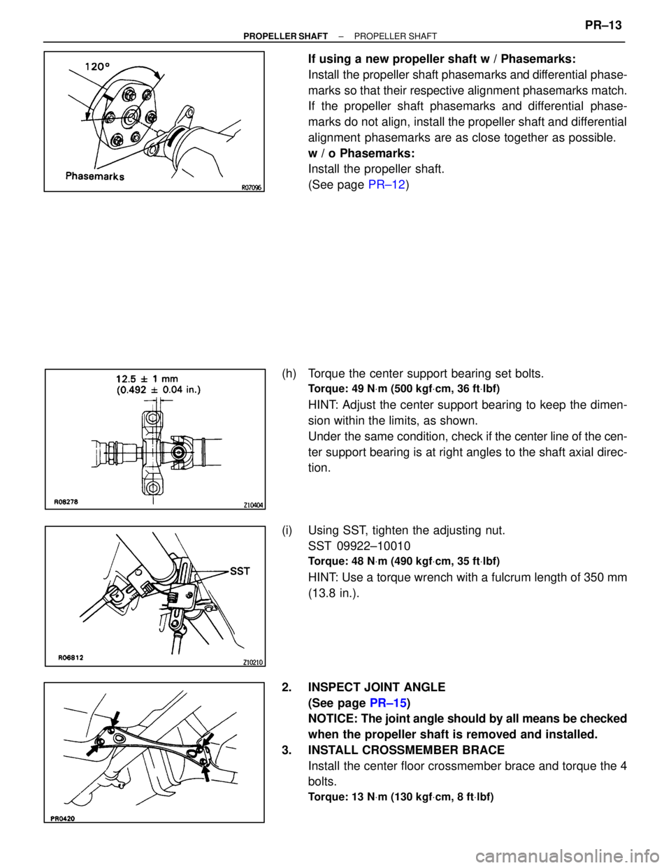
If using a new propeller shaft w / Phasemarks:
Install the propeller shaft phasemarks and differential phase-
marks so that their respective alignment phasemarks match.
If the propeller shaft phasemarks and differential phase-
marks do not align, install the propeller shaft and differential
alignment phasemarks are as close together as possible.
w / o Phasemarks:
Install the propeller shaft.
(See page PR±12)
(h) Torque the center support bearing set bolts.
Torque: 49 N Vm (500 kgf Vcm, 36 ft Vlbf)
HINT: Adjust the center support bearing to keep the dimen-
sion within the limits, as shown.
Under the same condition, check if the center line of the cen-
ter support bearing is at right angles to the shaft axial direc-
tion.
(i) Using SST, tighten the adjusting nut. SST 09922±10010
Torque: 48 N Vm (490 kgf Vcm, 35 ft Vlbf)
HINT: Use a torque wrench with a fulcrum length of 350 mm
(13.8 in.).
2. INSPECT JOINT ANGLE (See page PR±15)
NOTICE: The joint angle should by all means be checked
when the propeller shaft is removed and installed.
3. INSTALL CROSSMEMBER BRACE Install the center floor crossmember brace and torque the 4
bolts.
Torque: 13 N Vm (130 kgf Vcm, 8 ft Vlbf)
±
PROPELLER SHAFT PROPELLER SHAFTPR±13
WhereEverybodyKnowsYourName
Page 2224 of 4087
(b) Install a new gasket and throttle body with the two boltsand two nuts.
Torque: 18 N Vm (185 kgf Vcm, 13 ft Vlbf)
HINT: Use bolts 40 mm (1.57 in.) in length.
(c) Install the water by±pass pipe (from rear water by±pass
joint) to the clamp on the engine wire cover.
(d) Connect the following hoses: (1) Water by±pass hose to the ISC valve
(2) (USA Spec.) Vacuum hose to throttle body
(3) (Exc. USA Spec.) Three vacuum hoses to throttle body
(e) Connect the following connectors: (1) Throttle position sensor connector
(2) (w/ TRAC) Sub±throttle position sensor connector
(3) (w/ TRAC) Sub±throttle actuator
27. REINSTALL HEATER WATER VALVE (a) Install the water valve and bracket assembly with thetwo bolts.
(b) Install the engine wire clamp with the bolt.
(c) Connect the VSV connector.
EM±24
±
ENGINE MECHANICAL Engine Tune±Up
WhereEverybodyKnowsYourName
Page 2225 of 4087
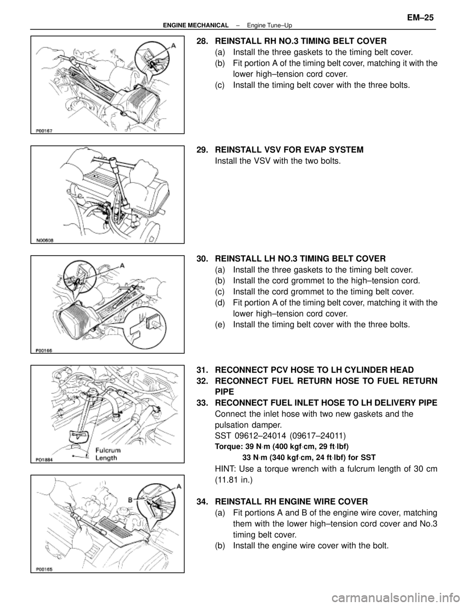
28. REINSTALL RH NO.3 TIMING BELT COVER(a) Install the three gaskets to the timing belt cover.
(b) Fit portion A of the timing belt cover, matching it with the
lower high±tension cord cover.
(c) Install the timing belt cover with the three bolts.
29. REINSTALL VSV FOR EVAP SYSTEM Install the VSV with the two bolts.
30. REINSTALL LH NO.3 TIMING BELT COVER (a) Install the three gaskets to the timing belt cover.
(b) Install the cord grommet to the high±tension cord.
(c) Install the cord grommet to the timing belt cover.
(d) Fit portion A of the timing belt cover, matching it with the
lower high±tension cord cover.
(e) Install the timing belt cover with the three bolts.
31. RECONNECT PCV HOSE TO LH CYLINDER HEAD
32. RECONNECT FUEL RETURN HOSE TO FUEL RETURN PIPE
33. RECONNECT FUEL INLET HOSE TO LH DELIVERY PIPE Connect the inlet hose with two new gaskets and the
pulsation damper.
SST 09612±24014 (09617±24011)
Torque: 39 N Vm (400 kgf Vcm, 29 ft Vlbf)
33 N Vm (340 kgf Vcm, 24 ft Vlbf) for SST
HINT: Use a torque wrench with a fulcrum length of 30 cm
(11.81 in.)
34. REINSTALL RH ENGINE WIRE COVER (a) Fit portions A and B of the engine wire cover, matchingthem with the lower high±tension cord cover and No.3
timing belt cover.
(b) Install the engine wire cover with the bolt.
±
ENGINE MECHANICAL Engine Tune±UpEM±25
WhereEverybodyKnowsYourName