Page 2057 of 4087
(b) Temporarily install a new gasket and the EGR pipe to air
intake chamber with the two bolt.
(c) (Exc. USA Spec.) Install the connector bracket to check (ºDIAGNOSISº)
connector.
(d) Install the air intake chamber and following parts with the four bolts and eight nuts:
(1) Check (ºDIAGNOSISº) connector
(2) A/T throttle cable bracket
(3) VSV for fuel pressure control system
(4) VSV for EGR system
Torque: 18 N Vm (185 kgf Vcm, 13 ft Vlbf)
HINT: Use bolts 40 mm (1.57 in.) of length.
(e) Tighten the bolt holding the EGR pipe to the air intake
chamber.
Torque: 18 N Vm (185 kgf Vcm, 13 ft Vlbf)
(f) Connect the cold start injector tube to the RH delivery
pipe with two new gaskets and union bolt.
Torque: 15 N Vm (150 kgf Vcm, 11 ft Vlbf)
FI±36EFI SYSTEM ± Fuel System (Cold Start Injector)
WhereEverybodyKnowsYourName
Page 2059 of 4087
4. CONNECT CONNECTORSConnect the following connectors:w Cold start injector connector
w ISC valve connector
w (USA Spec.)
EGR valve connector
w (Exc. USA Spec.)
VSV connector for EGR system
w SV connector for fuel pressure control system
5. INSTALL THROTTLE BODY (a) Connect the following hoses:(1) PCV hose to throttle body
(2) Water by±pass hose to throttle body
(b) Install a new gasket and throttle body with the two bolts and two nuts.
Torque: 18 N Vm (185 kgf Vcm, 13 ft Vlbf)
HINT: Use bolts 40 mm (1.57 in.) in length.
(c) Install the water by±pass pipe (from rear water bypass
joint) to the clamp on the engine wire cover.
(d) Connect the following hoses: (1) Water by±pass hose to the ISC valve
(2) (USA Spec.) Vacuum hose to throttle body
(3) (Exc. USA Spec.) Three vacuum hoses to throttle body
FI±38
EFI SYSTEM
± Fuel System (Cold Start Injector)
WhereEverybodyKnowsYourName
Page 2068 of 4087

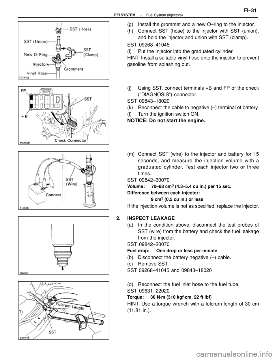
(g) Install the grommet and a new O±ring to the injector.
(h) Connect SST (hose) to the injector with SST (union),and hold the injector and union with SST (clamp).
SST 09268±41045
(i) Put the injector into the graduated cylinder.
HINT: Install a suitable vinyl hose onto the injector to prevent
gasoline from splashing out.
(j) Using SST, connect terminals +B and FP of the check (ºDIAGNOSISº) connector.
SST 09843±18020
(k) Reconnect the cable to negative (±) terminal of battery.
(l) Turn the ignition switch ON.
NOTICE: Do not start the engine.
(m) Connect SST (wire) to the injector and battery for 15 seconds, and measure the injection volume with a
graduated cylinder. Test each injector two or three
times.
SST 09842±30070
Volume: 70±88 cm3 (4.3±5.4 cu in.) per 15 sec.
Difference between each injector:
9 cm
3 (0.5 cu in.) or less
If the injection volume is not as specified, replace the injector.
2. INSPECT LEAKAGE (a) In the condition above, disconnect the test probes ofSST (wire) from the battery and check the fuel leakage
from the injector.
SST 09842±30070
Fuel drop: One drop or less per minute
(b) Disconnect the battery negative (±) cable.
(c) Remove SST.
SST 09268±41045 and 09843±18020
(d) Reconnect the fuel inlet hose to the fuel tube.
SST 09631±22020
Torque: 30 N Vm (310 kgf Vcm, 22 ft Vlbf)
HINT: Use a torque wrench with a fulcrum length of 30 cm
(11.81 in.).
±
EFI SYSTEM Fuel System (Injectors)FI±31
WhereEverybodyKnowsYourName
Page 2073 of 4087
INSTALLATION OF FUEL PRESSURE
PULSATION DAMPER
(See Components on page FI±35)
1. INSTALL FUEL PRESSURE PULSATION DAMPER (a) In sta ll two ne w ga ske ts, th e No . 1 fu e l pip e an dpulsation damper.
(b) Using SST, torque the pulsation damper.
SST 09612±24014 (09617±24011)
Torque: 41 N Vm (420 kgf Vcm, 30 ft Vlbf)
35 N Vm (350 kgf Vcm, 25 ft Vlbf) for SST
HINT: Use a torque wrench with a fulcrum length of 30 cm
(11.81 in.).
2. INSTALL STARTER (See page ST±5)
Torque: 39 N Vm (400 kgf Vcm, 29 ft Vlbf)
3. (A/T)
INSTALL DIPSTICK GUIDE FOR TRANSMISSION
(a) Install a new O±ring to the dipstick guide.
(b) Apply soapy water to the O±ring.
(c) Connect the dipstick guide end to the tube of the oil pan,
and install the dipstick guide with the bolt.
(d) Install the dipstick.
4. CHECK FOR FUEL LEAKS (See page FI±15)
FI±36
±
EFI SYSTEM Fuel System (Fuel Pressure Pulsation Damper)
WhereEverybodyKnowsYourName
Page 2114 of 4087

INSTALLATION OF DISTRIBUTOR
(See Components on page IG±23)
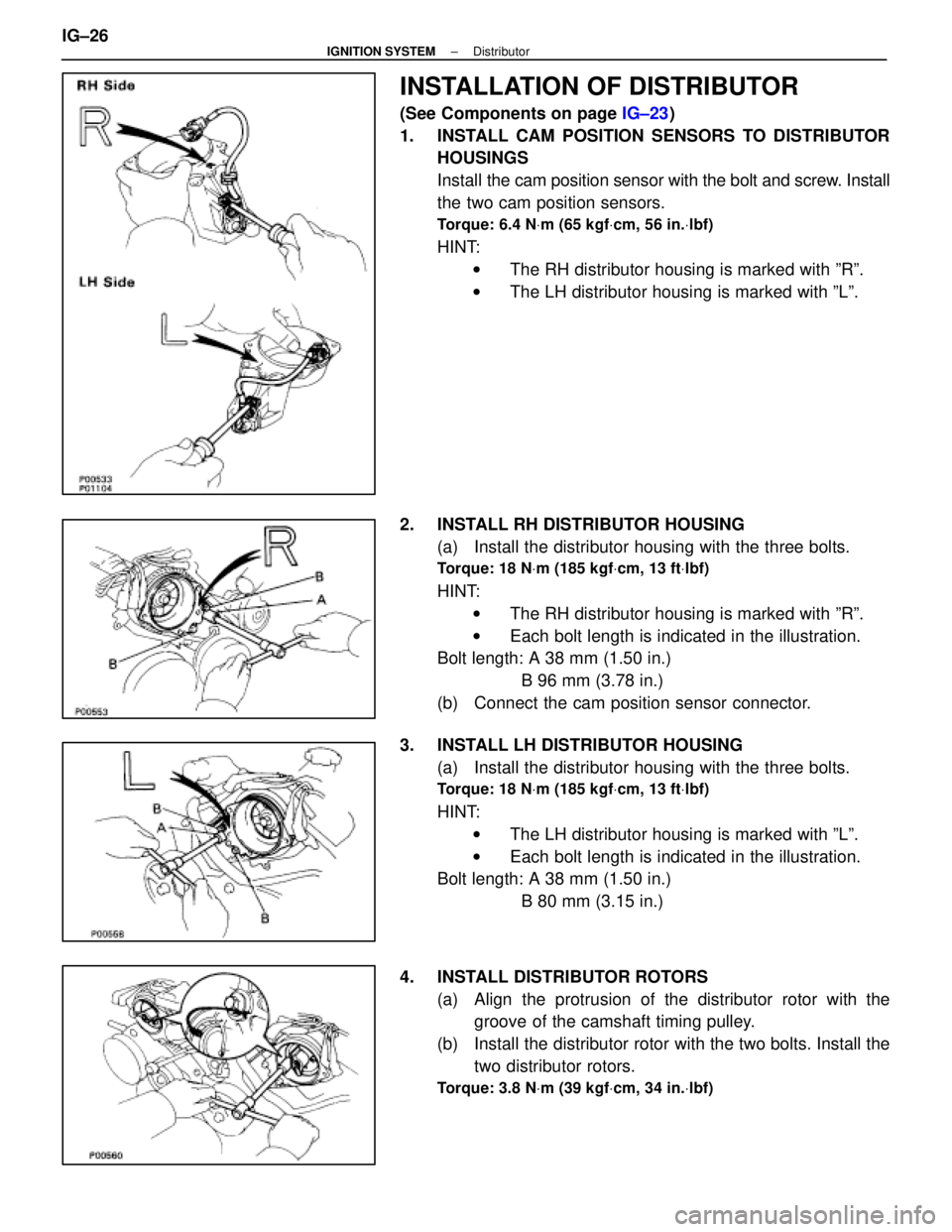
1. INSTALL CAM POSITION SENSORS TO DISTRIBUTOR HOUSINGS
Install the cam position sensor with the bolt and screw. Install
the two cam position sensors.
Torque: 6.4 N Vm (65 kgf Vcm, 56 in. Vlbf)
HINT:
w The RH distributor housing is marked with ºRº.
w The LH distributor housing is marked with ºLº.
2. INSTALL RH DISTRIBUTOR HOUSING (a) Install the distributor housing with the three bolts.
Torque: 18 N Vm (185 kgf Vcm, 13 ft Vlbf)
HINT:
w The RH distributor housing is marked with ºRº.
w Each bolt length is indicated in the illustration.
Bolt length: A 38 mm (1.50 in.)
B 96 mm (3.78 in.)
(b) Connect the cam position sensor connector.
3. INSTALL LH DISTRIBUTOR HOUSING (a) Install the distributor housing with the three bolts.
Torque: 18 N Vm (185 kgf Vcm, 13 ft Vlbf)
HINT:
w The LH distributor housing is marked with ºLº.
w Each bolt length is indicated in the illustration.
Bolt length: A 38 mm (1.50 in.)
B 80 mm (3.15 in.)
4. INSTALL DISTRIBUTOR ROTORS (a) Align the protrusion of the distributor rotor with thegroove of the camshaft timing pulley.
(b) Install the distributor rotor with the two bolts. Install the two distributor rotors.
Torque: 3.8 N Vm (39 kgf Vcm, 34 in. Vlbf)
IG±26±
IGNITION SYSTEM Distributor
WhereEverybodyKnowsYourName
Page 2115 of 4087

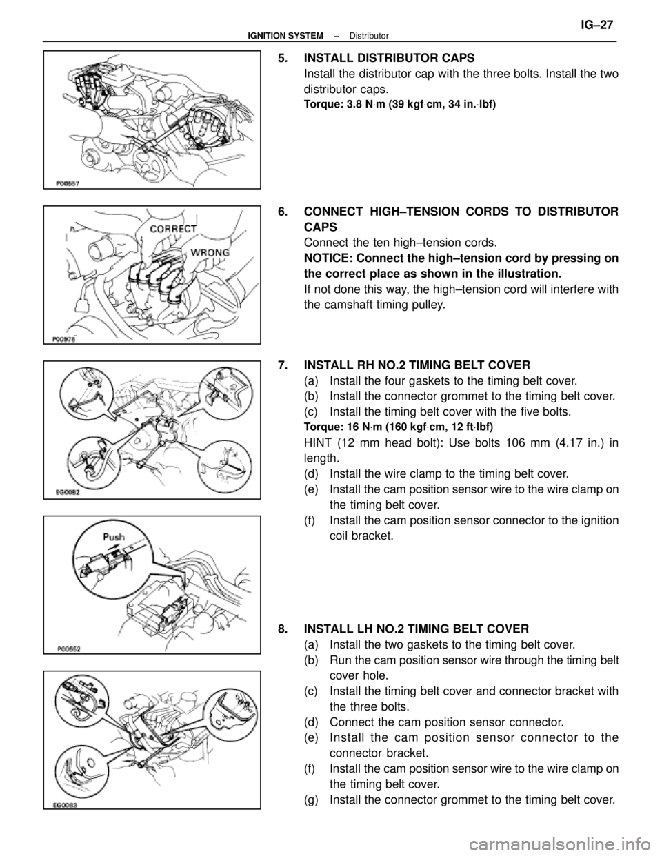
5. INSTALL DISTRIBUTOR CAPSInstall the distributor cap with the three bolts. Install the two
distributor caps.
Torque: 3.8 N Vm (39 kgf Vcm, 34 in. Vlbf)
6. CONNECT HIGH±TENSION CORDS TO DISTRIBUTOR
CAPS
Connect the ten high±tension cords.
NOTICE: Connect the high±tension cord by pressing on
the correct place as shown in the illustration.
If not done this way, the high±tension cord will interfere with
the camshaft timing pulley.
7. INSTALL RH NO.2 TIMING BELT COVER (a) Install the four gaskets to the timing belt cover.
(b) Install the connector grommet to the timing belt cover.
(c) Install the timing belt cover with the five bolts.
Torque: 16 N Vm (160 kgf Vcm, 12 ft Vlbf)
HINT (12 mm head bolt): Use bolts 106 mm (4.17 in.) in
length.
(d) Install the wire clamp to the timing belt cover.
(e) Install the cam position sensor wire to the wire clamp on
the timing belt cover.
(f) Install the cam position sensor connector to the ignition coil bracket.
8. INSTALL LH NO.2 TIMING BELT COVER (a) Install the two gaskets to the timing belt cover.
(b) Run the cam po sition sensor wire through the timing belt
cover hole.
(c) Install the timing belt cover and connector bracket with the three bolts.
(d) Connect the cam position sensor connector.
(e) In sta ll th e ca m po sitio n se n so r c onnector to the
connector bracket.
(f) Install the cam position sensor wire to the wire clamp on
the timing belt cover.
(g) Install the connector grommet to the timing belt cover.
±
IGNITION SYSTEM DistributorIG±27
WhereEverybodyKnowsYourName
Page 2127 of 4087

REPLACEMENT OF ENGINE OIL
AND OIL FILTER
CAUTION:
wProlonged and repeated contact with mineral oil will
result in the removal of natural fats from the skin, leading
to dryness, irritation and dermatitis. In addition, used
engine oil contains potentially harmful contaminants
which may cause skin cancer.
w Exerise caution in order to minimize the length and
frequency of contact of your skin to used oil. Wear
protective clothing and gloves. The skin s hould be
thoroughly w ashed with soap and water, or use waterless
hand cleaner, to remove any used engine oil. Do not use
gasoline, thinners, or solvents.
w In order to preserve the environment, used oil and used
oil filter must be disposed of only at designated disposal
sites.
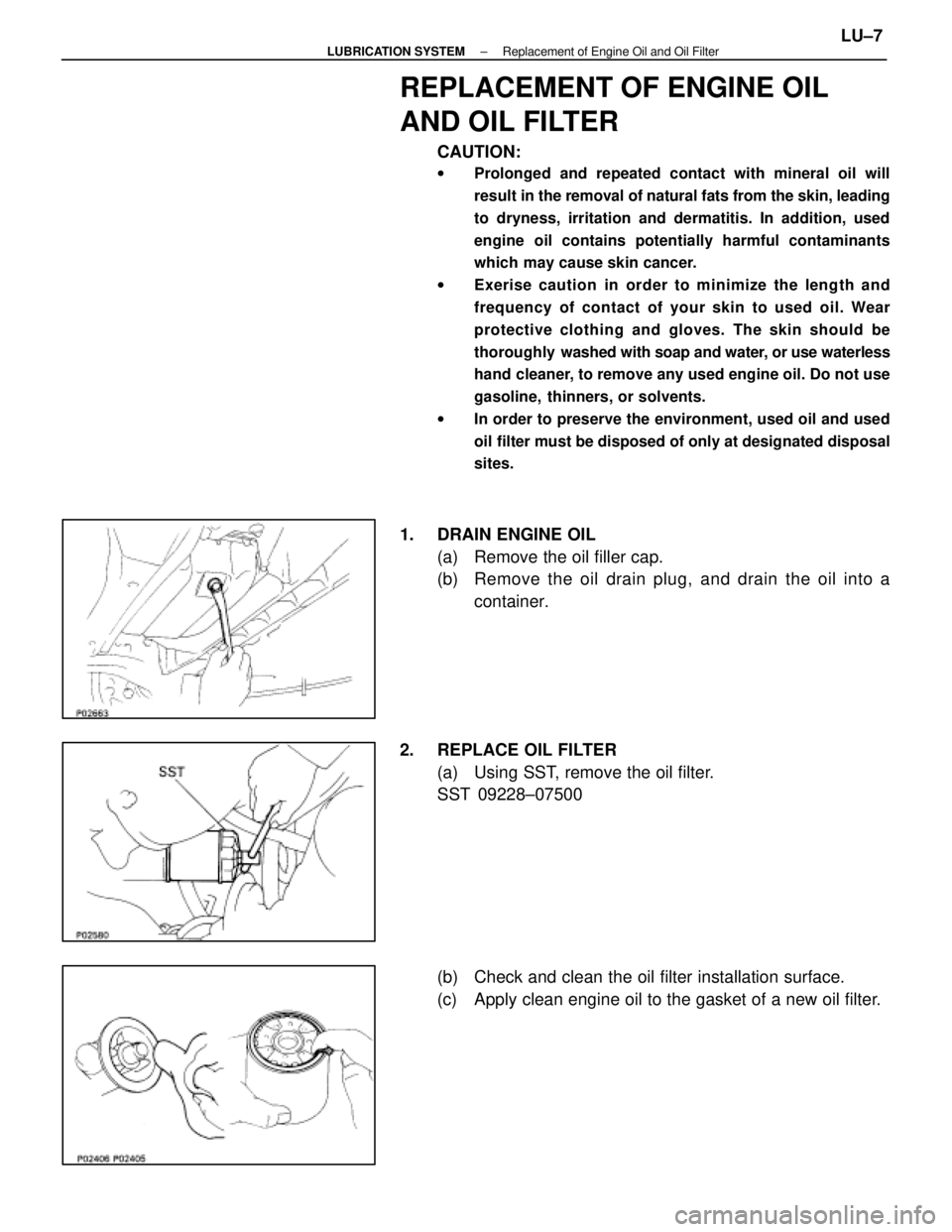
1. DRAIN ENGINE OIL
(a) Remove the oil filler cap.
(b) Remove the oil drain plug, and drain the oil into acontainer.
2. REPLACE OIL FILTER (a) Using SST, remove the oil filter.
SST 09228±07500
(b) Check and clean the oil filter installation surface.
(c) Apply clean engine oil to the gasket of a new oil filter.
±
LUBRICATION SYSTEM Replacement of Engine Oil and Oil FilterLU±7
WhereEverybodyKnowsYourName
Page 2137 of 4087
(e) Install the oil pump with the eight bolts.
Torque:12 mm head 16 N Vm (160 kgf Vcm, 12 ft Vlbf)
14 mm head 30 N Vm (310 kgf Vcm, 22 ft Vlbf)
HINT: Each bolt length is indicated in the illustration.
Bolt length:
A 50 mm (1.97 in.) for 12 mm head
B 106 mm (4.17 in.) for 12 mm head
C 30 mm (1.18 in.) for 12 mm head
D 40 mm (1.57 in.) for 14 mm head
2. INSTALL ENGINE SPEED SENSOR (a) Install the speed sensor with the bolt.
Torque: 6.4 N Vm (65 kgf Vcm, 56 in. Vlbf)
(b) Connect the speed sensor connector.
3. INSTALL OIL FILTER BRACKET (a) Place a new gasket in position on the oil filter bracket.
(b) Install the oil filter bracket with the two bolts and studbolt.
Torque: 18 N Vm (185 kgf Vcm, 13 ft Vlbf)
(c) Connect the oil pressure switch connector.
4. INSTALL OIL STRAINER Install a new gasket and the oil strainer with the two bolts and
two nuts.
Torque: 7.8 N Vm (80 kgf Vcm, 69 in. Vlbf)
LU±16±
LUBRICATION SYSTEM Oil Pump
WhereEverybodyKnowsYourName