Page 1884 of 4087
7. CONNECT FUEL RETURN HOSE TO FUEL RETURN PIPE
8. CONNECT FUEL INLET HOSE TO LH DELIVERY PIPE Using SST, connect the inlet hose with two new gaskets and
pulsation damper.
SST 09612±24014 (09617±24011)
Torque: 39 N Vm (400 kgf Vcm, 29 ft Vlbf)
33 N Vm (340 kgf Vcm, 24 ft Vlbf) for SST
HINT: Use a torque wrench with a fulcrum length of 30 cm
(11.81 in.).
9. INSTALL AIR INTAKE CHAMBER (See steps 2 to 18 on pages FI±35 to 41)
HINT: After the air intake chamber installed, tighten the bolt
holding to the EGR pipe to the RH cylinder head. FI±57
EFI SYSTEM
± Fuel System (Injectors)
WhereEverybodyKnowsYourName
Page 1897 of 4087
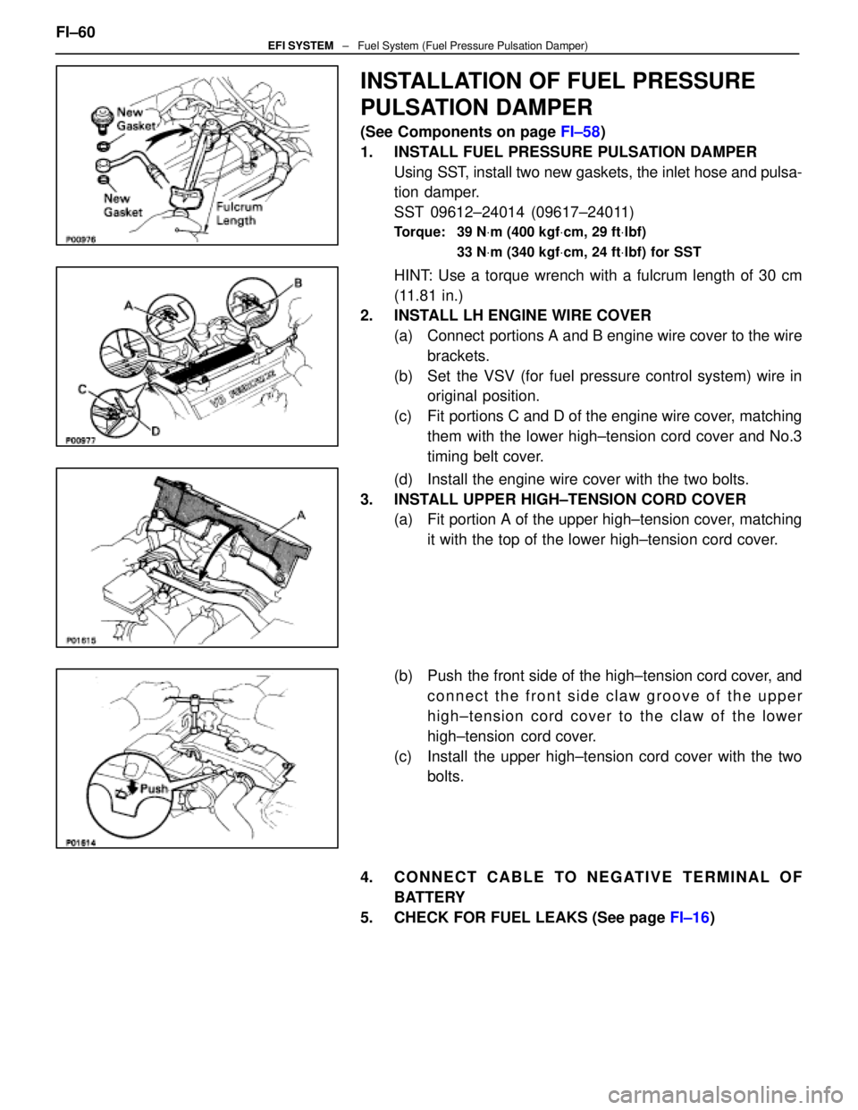
INSTALLATION OF FUEL PRESSURE
PULSATION DAMPER
(See Components on page FI±58)
1. INSTALL FUEL PRESSURE PULSATION DAMPER Using SST, install two new gaskets, the inlet hose and pulsa-
tion damper.
SST 09612±24014 (09617±24011)
Torque: 39 N Vm (400 kgf Vcm, 29 ft Vlbf)
33 N Vm (340 kgf Vcm, 24 ft Vlbf) for SST
HINT: Use a torque wrench with a fulcrum length of 30 cm
(11.81 in.)
2. INSTALL LH ENGINE WIRE COVER
(a) Connect portions A and B engine wire cover to the wirebrackets.
(b) Set the VSV (for fuel pressure control system) wire in original position.
(c) Fit portions C and D of the engine wire cover, matching them with the lower high±tension cord cover and No.3
timing belt cover.
(d) Install the engine wire cover with the two bolts.
3. INSTALL UPPER HIGH±TENSION CORD COVER (a) Fit portion A of the upper high±tension cover, matching
it with the top of the lower high±tension cord cover.
(b) Push the front side of the high±tension cord cover, and connect the front side claw groove of the upper
high±tension cord cover to the claw of the lower
high±tension cord cover.
(c) Install the upper high±tension cord cover with the two bolts.
4. CONNECT CABLE TO NEGATIVE TERMINAL OF BATTERY
5. CHECK FOR FUEL LEAKS (See page FI±16)
FI±60
EFI SYSTEM
± Fuel System (Fuel Pressure Pulsation Damper)
WhereEverybodyKnowsYourName
Page 1916 of 4087
INSTALLATION OF THROTTLE BODY
(See Components o page FI±69)
1. INSTALL THROTTLE BODY (a) Install the two water by±pass hoses and pipe to thethrottle body.
(b) Connect the following hoses: (1) PCV hose to throttle body
(2) Water by±pass hose to throttle body
(c) Install a new gasket and throttle body with the two bolts and two nuts.
Torque: 18 N Vm (185 kgf Vcm, 13 ft Vlbf)
HINT: Use bolts 40 mm (1.57 in.) in length.
(d) Install the water by±pass pipe (from rear water by±pass
joint) to the clamp on the engine wire cover.
(e) Connect the following hoses: (1) Water by±pass hose to the ISC valve
(2) (USA Spec.) Vacuum hose to throttle body
(3) (Exc. USA Spec.) Three vacuum hoses to throttle body FI±77
EFI SYSTEM
± Air Induction System (Throttle Body)
WhereEverybodyKnowsYourName
Page 1965 of 4087
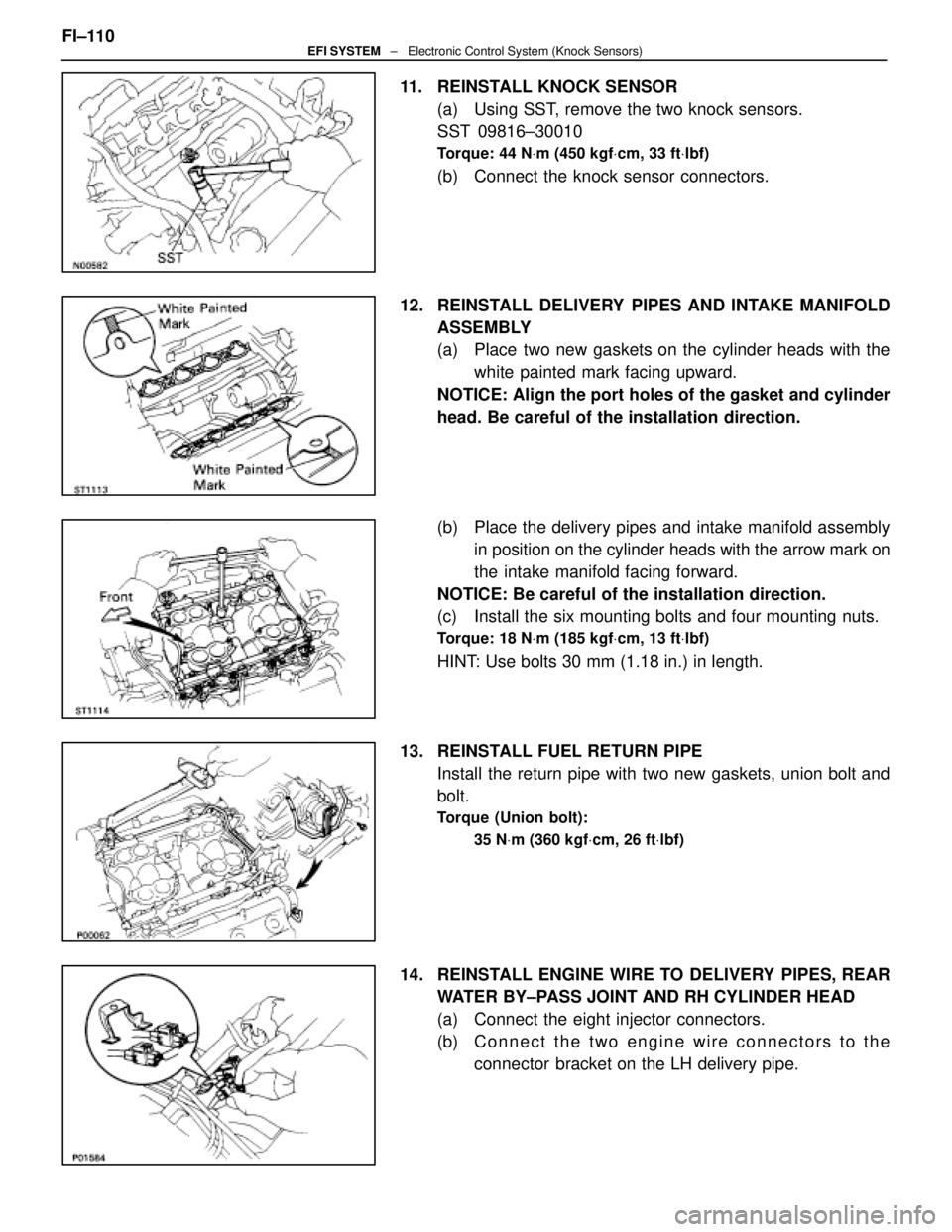
11. REINSTALL KNOCK SENSOR(a) Using SST, remove the two knock sensors.
SST 09816±30010
Torque: 44 N Vm (450 kgf Vcm, 33 ft Vlbf)
(b) Connect the knock sensor connectors.
12. REINSTALL DELIVERY PIPES AND INTAKE MANIFOLD ASSEMBLY
(a) Place two new gaskets on the cylinder heads with thewhite painted mark facing upward.
NOTICE: Align the port holes of the gasket and cylinder
head. Be careful of the installation direction.
(b) Place the delivery pipes and intake manifold assembly in position on the cylinder heads with the arrow mark on
the intake manifold facing forward.
NOTICE: Be careful of the installation direction.
(c) Install the six mounting bolts and four mounting nuts.
Torque: 18 N Vm (185 kgf Vcm, 13 ft Vlbf)
HINT: Use bolts 30 mm (1.18 in.) in length.
13. REINSTALL FUEL RETURN PIPE Install the return pipe with two new gaskets, union bolt and
bolt.
Torque (Union bolt):
35 NVm (360 kgf Vcm, 26 ft Vlbf)
14. REINSTALL ENGINE WIRE TO DELIVERY PIPES, REAR
WATER BY±PASS JOINT AND RH CYLINDER HEAD
(a) Connect the eight injector connectors.
(b) C onnect the two engine wire connectors to the
connector bracket on the LH delivery pipe.
FI±110
EFI SYSTEM
± Electronic Control System (Knock Sensors)
WhereEverybodyKnowsYourName
Page 1966 of 4087
(c) Install the engine wire to the RH cylinder head with thetwo bolts.
(d) Install the engine wire to the rear water by±pass joint with the two bolts.
(e) Install the engine wire to the delivery pipes with the four bolts.
15. REINSTALL ENGINE WIRE TO INTAKE MANIFOLD Install the engine wire with the two bolts.
16. TEMPORARILY REINSTALL EGR PIPE TO RH CYLINDER
HEAD
Temporarily Install the EGR pipe with the bolt.
17. RECONNECT FUEL RETURN HOSE TO FUEL RETURN PIPE
18. RECONNECT FUEL INLET HOSE TO LH DELIVERY PIPE
Using SST, connect the inlet hose with two new gaskets and
pulsation damper.
SST 09612±24014 (09617±24011)
Torque: 39 N Vm (400 kgf Vcm, 29 ft Vlbf)
33 N Vm (340 kgf Vcm, 24 ft Vlbf) for SST
HINT: Use a torque wrench with a fulcrum length of 30 cm
(11.81 in.). FI±111
EFI SYSTEM
± Electronic Control System (Knock Sensors)
WhereEverybodyKnowsYourName
Page 2007 of 4087
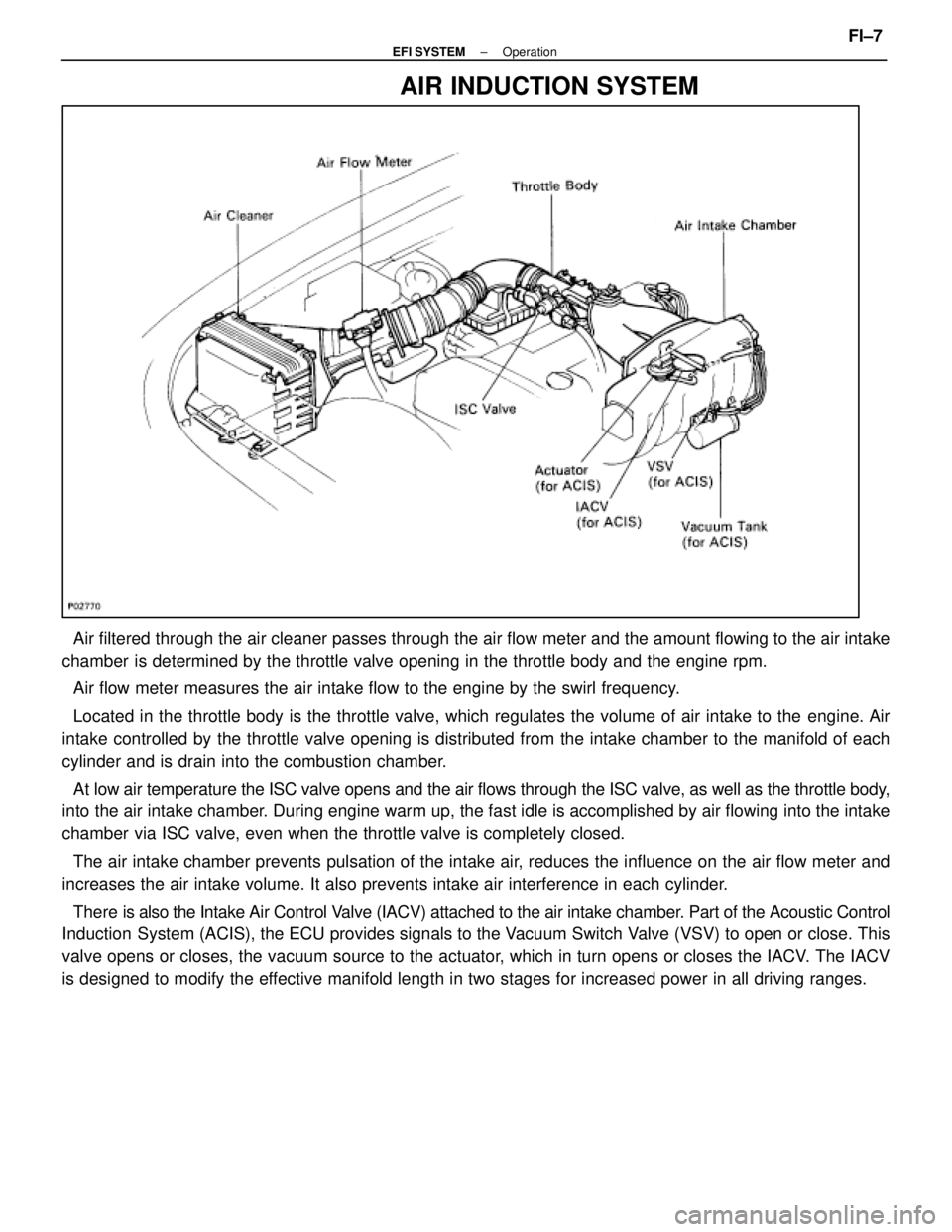
AIR INDUCTION SYSTEM
Air filtered through the air cleaner passes through the air flow meter a\
nd the amount flowing to the air intake
chamber is determined by the throttle valve opening in the throttle body and th\
e engine rpm.
Air flow meter measures the air intake flow to the engine by the swirl f\
requency.
Located in the throttle body is the throttle valve, which regulates the \
volume of air intake to the engine. Air
intake controlled by the throttle valve opening is distributed from the \
intake chamber to the manifold of each
cylinder and is drain into the combustion chamber.
At low air temperature the ISC valve opens and the air flows through the I\
SC valve, as well as the throttle body,
into the air intake chamber. During engine warm up, the fast idle is accomplished by air flowing into the intake
chamber via ISC valve, even when the throttle valve is completely closed.
The air intake chamber prevents pulsation of the intake air, reduces the influence on the air flow meter and
increases the air intake volume. It also prevents intake air interferenc\
e in each cylinder.
There is also the Int ake Air Control Valve (IACV) attached to the air intake chamber. Part of the Acoustic Control
Induction System (ACIS), the ECU provides signals to the Vacuum Switch Valve (VSV) to open or close. This
valve opens or closes, the vacuum source to the actuator, which in turn opens or closes the IACV. The IACV
is designed to modify the effective manifold length in two stages for increased power in all driving\
ranges.
±
EFI SYSTEM OperationFI±7
WhereEverybodyKnowsYourName
Page 2021 of 4087
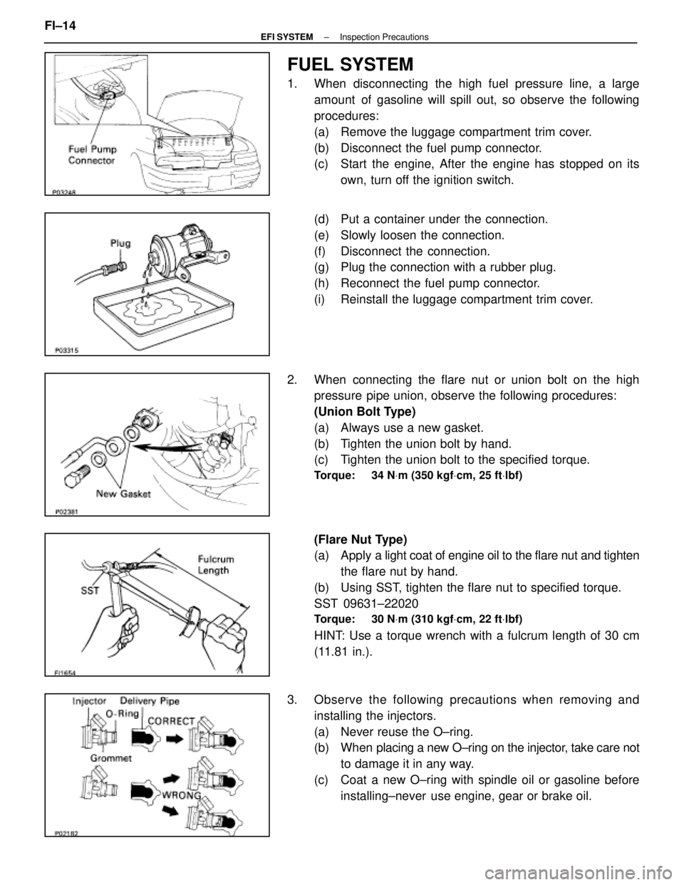
FUEL SYSTEM
1. When disconnecting the high fuel pressure line, a largeamount of gasoline will spill out, so observe the following
procedures:
(a) Remove the luggage compartment trim cover.
(b) Disconnect the fuel pump connector.
(c) Start the engine, After the engine has stopped on itsown, turn off the ignition switch.
(d) Put a container under the connection.
(e) Slowly loosen the connection.
(f) Disconnect the connection.
(g) Plug the connection with a rubber plug.
(h) Reconnect the fuel pump connector.
(i) Reinstall the luggage compartment trim cover.
2. When connecting the flare nut or union bolt on the high pressure pipe union, observe the following procedures:
(Union Bolt Type)
(a) Always use a new gasket.
(b) Tighten the union bolt by hand.
(c) Tighten the union bolt to the specified torque.
Torque: 34 N Vm (350 kgf Vcm, 25 ft Vlbf)
(Flare Nut Type)
(a) Apply a light coat of engine oil to the flare nut and tighten
the flare nut by hand.
(b) Using SST, tighten the flare nut to specified torque.
SST 09631±22020
Torque: 30 N Vm (310 kgf Vcm, 22 ft Vlbf)
HINT: Use a torque wrench with a fulcrum length of 30 cm
(11.81 in.).
3. Observe the following precautions when removing and installing the injectors.
(a) Never reuse the O±ring.
(b) When placing a new O±ring on the injector, take care not
to damage it in any way.
(c) Coat a new O±ring with spindle oil or gasoline before installing±never use engine, gear or brake oil.
FI±14
±
EFI SYSTEM Inspection Precautions
WhereEverybodyKnowsYourName
Page 2026 of 4087
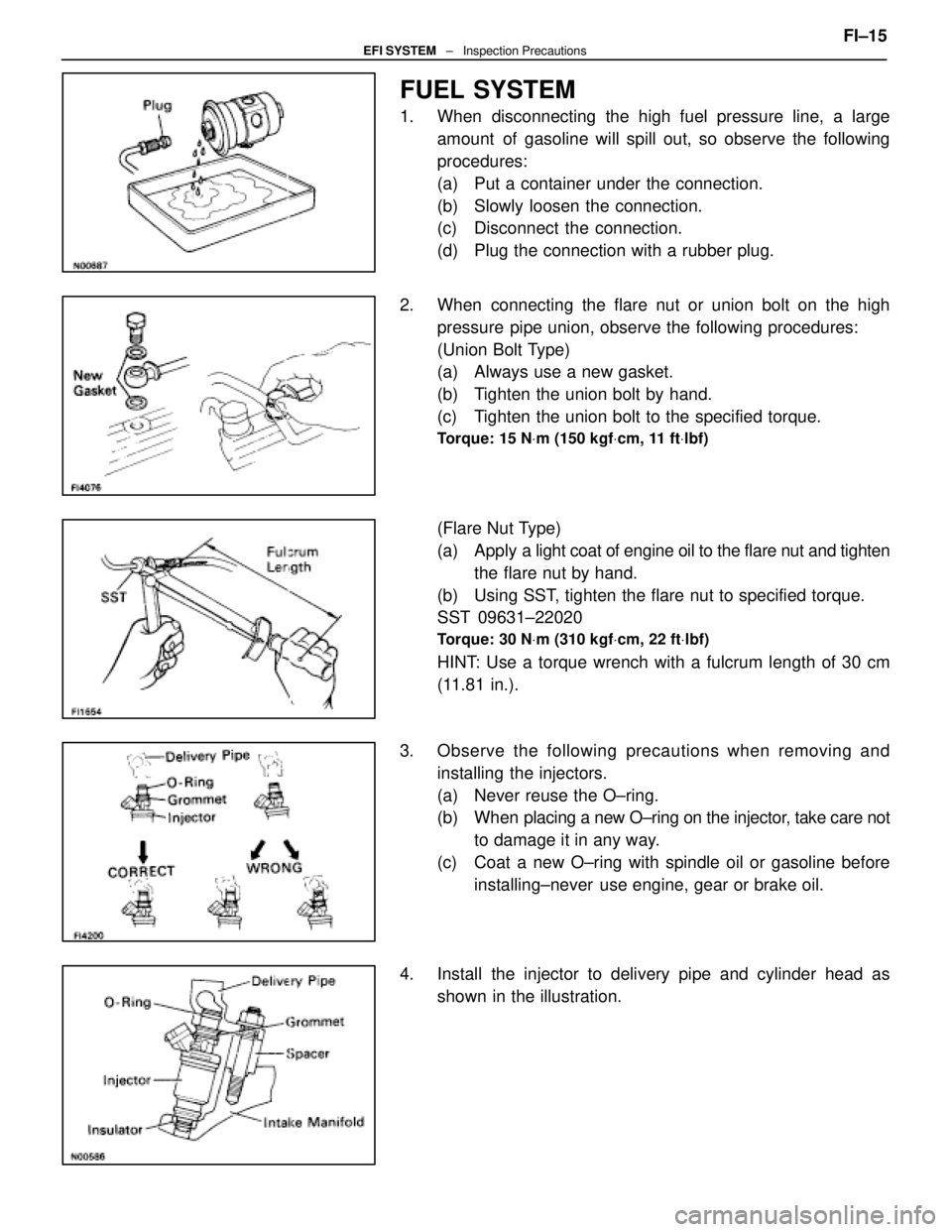
FUEL SYSTEM
1. When disconnecting the high fuel pressure line, a largeamount of gasoline will spill out, so observe the following
procedures:
(a) Put a container under the connection.
(b) Slowly loosen the connection.
(c) Disconnect the connection.
(d) Plug the connection with a rubber plug.
2. When connecting the flare nut or union bolt on the high pressure pipe union, observe the following procedures:
(Union Bolt Type)
(a) Always use a new gasket.
(b) Tighten the union bolt by hand.
(c) Tighten the union bolt to the specified torque.
Torque: 15 N Vm (150 kgf Vcm, 11 ft Vlbf)
(Flare Nut Type)
(a) Apply a light coat of engine oil to the flare nut and tighten
the flare nut by hand.
(b) Using SST, tighten the flare nut to specified torque.
SST 09631±22020
Torque: 30 N Vm (310 kgf Vcm, 22 ft Vlbf)
HINT: Use a torque wrench with a fulcrum length of 30 cm
(11.81 in.).
3. Observe the following precautions when removing and installing the injectors.
(a) Never reuse the O±ring.
(b) When placing a new O±ring on the injector, take care not
to damage it in any way.
(c) Coat a new O±ring with spindle oil or gasoline before installing±never use engine, gear or brake oil.
4. Install the injector to delivery pipe and cylinder head as shown in the illustration. FI±15
EFI SYSTEM
± Inspection Precautions
WhereEverybodyKnowsYourName