Page 1511 of 4087
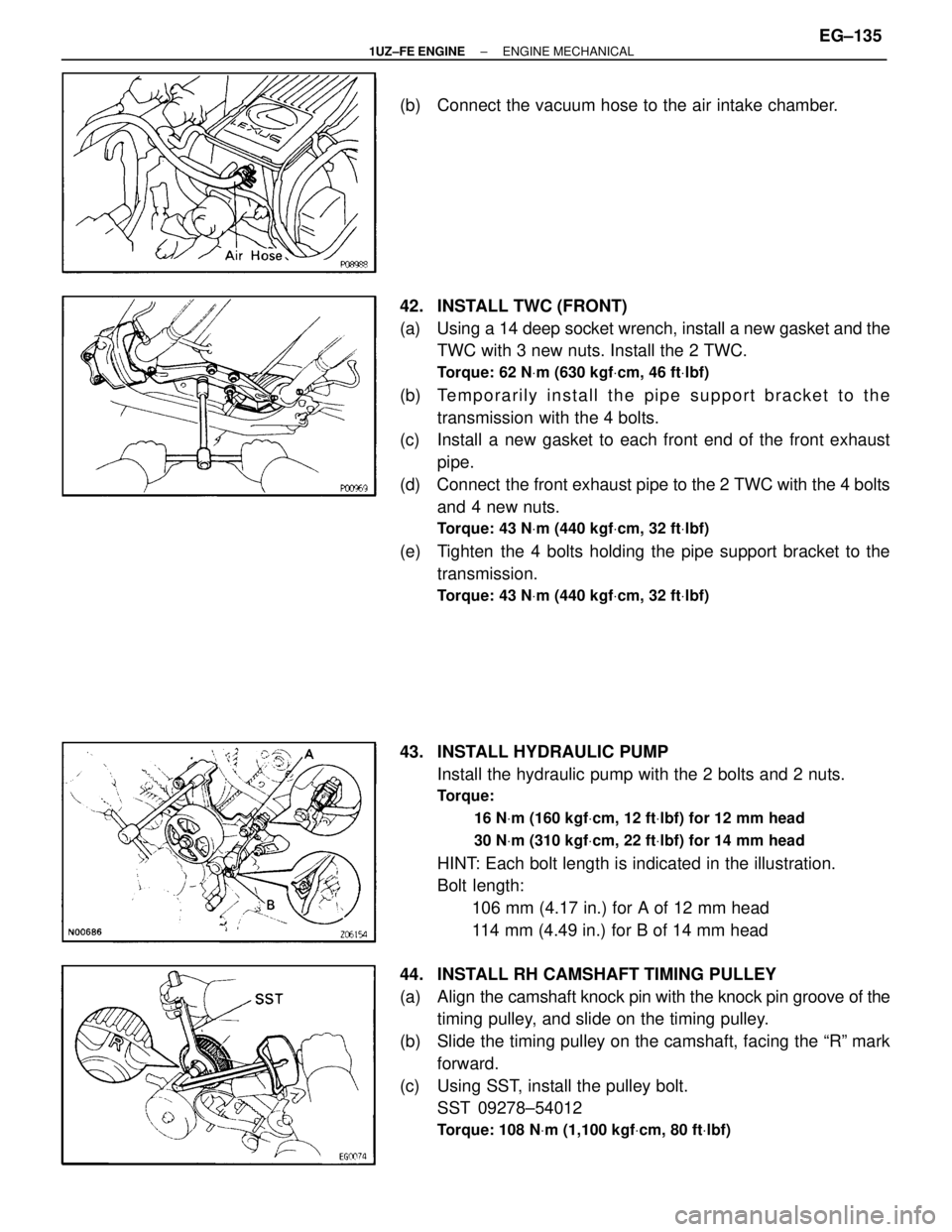
(b) Connect the vacuum hose to the air intake chamber.
42. INSTALL TWC (FRONT)
(a) Using a 14 deep socket wrench, install a new gasket and theTWC with 3 new nuts. Install the 2 TWC.
Torque: 62 N Vm (630 kgf Vcm, 46 ft Vlbf)
(b) Te m p o r a r i l y i n s t a l l t h e p i p e s upport bracket to the
transmission with the 4 bolts.
(c) Install a new gasket to each front end of the front exhaust
pipe.
(d) Connect the front exhaust pipe to the 2 TWC with the 4 bolts and 4 new nuts.
Torque: 43 N Vm (440 kgf Vcm, 32 ft Vlbf)
(e) Tighten the 4 bolts holding the pipe support bracket to the
transmission.
Torque: 43 N Vm (440 kgf Vcm, 32 ft Vlbf)
43. INSTALL HYDRAULIC PUMP
Install the hydraulic pump with the 2 bolts and 2 nuts.
Torque:
16 NVm (160 kgf Vcm, 12 ft Vlbf) for 12 mm head
30 N Vm (310 kgf Vcm, 22 ft Vlbf) for 14 mm head
HINT: Each bolt length is indicated in the illustration.
Bolt length:
106 mm (4.17 in.) for A of 12 mm head
114 mm (4.49 in.) for B of 14 mm head
44. INSTALL RH CAMSHAFT TIMING PULLEY
(a) Align the camshaft knock pin with the knock pin groove of the
timing pulley, and slide on the timing pulley.
(b) Slide the timing pulley on the camshaft, facing the ªRº mark forward.
(c) Using SST, install the pulley bolt. SST 09278±54012
Torque: 108 N Vm (1,100 kgf Vcm, 80 ft Vlbf)
±
1UZ±FE ENGINE ENGINE MECHANICALEG±135
WhereEverybodyKnowsYourName
Page 1543 of 4087
7. IF NECESSARY, REPLACE MAIN BEARING CAP STUDBOLTS
(a) Using the 2 main bearing cap nuts, remove the stud bolt.
(b) Apply a light coat of engine oil on the threads and under
flange of new stud bolts.
(c) Using the 2 main bearing cap nuts, install the stud bolt.
Torque: 15 N Vm (150 kgf Vcm, 11 ft Vlbf)
HINT: Stud bolts come in lengths of 90.0 mm (3.543 in.) and
101.5 mm (3.996 in.). Install the 101.5 mm (3.996 in.) bolts
in inside positions. Install the 90.0 mm (3.543 in.) bolts in out-
side positions.
PISTON AND CONNECTING ROD
DISASSEMBLY
EG0BV±06
1. CHECK FIT BETWEEN PISTON AND PISTON PIN
Try to move the piston back and forth on the piston pin.
If any movement is felt, replace the piston and pin as a set.
2. REMOVE PISTON RINGS
(a) Using a piston ring expander, remove the 2 compression rings.
±
1UZ±FE ENGINE ENGINE MECHANICALEG±167
WhereEverybodyKnowsYourName
Page 1562 of 4087
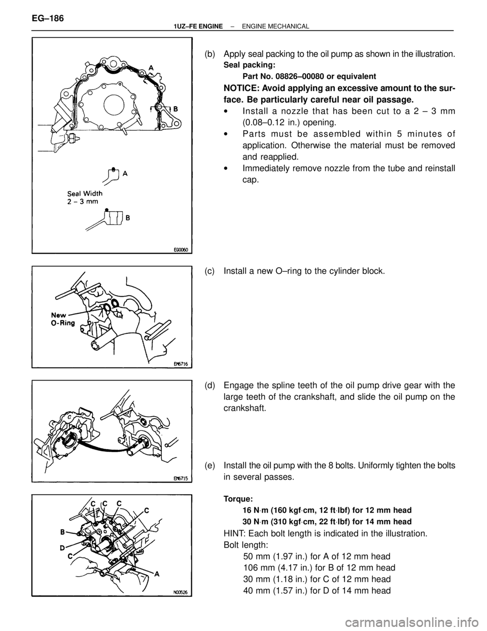
(b) Apply seal packing to the oil pump as shown in the illustration.
Seal packing:
Part No. 08826±00080 or equivalent
NOTICE: Avoid applying an excessive amount to the sur-
face. Be particularly careful near oil passage.
w In sta ll a no zzle th a t ha s be e n cu t to a 2 ± 3 mm
(0.08±0.12 in.) opening.
w Parts must be assembled within 5 minutes of
application. Otherwise the material must be removed
and reapplied.
w Immediately remove nozzle from the tube and reinstall
cap.
(c) Install a new O±ring to the cylinder block.
(d) Engage the spline teeth of the oil pump drive gear with the large teeth of the crankshaft, and slide the oil pump on the
crankshaft.
(e) Install the oil pump with the 8 bolts. Uniformly tighten the bolts
in several passes.
Torque:
16 NVm (160 kgf Vcm, 12 ft Vlbf) for 12 mm head
30 N Vm (310 kgf Vcm, 22 ft Vlbf) for 14 mm head
HINT: Each bolt length is indicated in the illustration.
Bolt length:
50 mm (1.97 in.) for A of 12 mm head
106 mm (4.17 in.) for B of 12 mm head
30 mm (1.18 in.) for C of 12 mm head
40 mm (1.57 in.) for D of 14 mm head
EG±186
±
1UZ±FE ENGINE ENGINE MECHANICAL
WhereEverybodyKnowsYourName
Page 1563 of 4087
4. INSTALL NO.1 AND NO.2 OIL PANS(See steps 1 to 7 on pages EG±509 to 511)
5. INSTALL WATER PUMP
(a) Remove any old packing (FIPG) material and be careful not to drop any oil on the contact surfaces of the water pump and
cylinder block.
wUsing a razor blade and gasket scraper, remove all the
old packing (FIPG) material from the gasket surfaces
and sealing groove.
w Thoroughly clean all components to remove all the
loose material.
w Using a non±residue solvent, clean both sealing
surfaces.
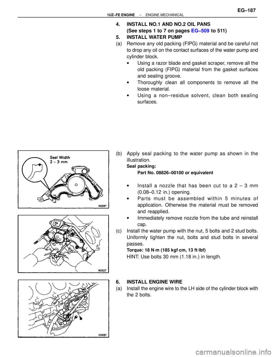
(b) Apply seal packing to the water pump as shown in the illustration.
Seal packing:
Part No. 08826±00100 or equivalent
wIn sta ll a no zzle th a t ha s be e n cu t to a 2 ± 3 mm
(0.08±0.12 in.) opening.
w Parts must be assembled within 5 minutes of
application. Otherwise the material must be removed
and reapplied.
w Immediately remove nozzle from the tube and reinstall
cap.
(c) Install the water pump with the nut, 5 bolts and 2 stud bolts. Uniformly tighten the nut, bolts and stud bolts in several
passes.
Torque: 18 N Vm (185 kgf Vcm, 13 ft Vlbf)
HINT: Use bolts 30 mm (1.18 in.) in length.
6. INSTALL ENGINE WIRE
(a) Install the engine wire to the LH side of the cylinder block with
the 2 bolts.
±
1UZ±FE ENGINE ENGINE MECHANICALEG±187
WhereEverybodyKnowsYourName
Page 1573 of 4087
12. INSTALL CHARCOAL CANISTER
(a) Install the charcoal canister.
(b) Connect the vacuum hose and air hose to the charcoalcanister.
13. CONNECT HOSES Connect the following hoses and ground strap:
(1) Heater water hose to water bypass hose
(2) Heater water hose to heater water valve
(3) Brake booster hose to union on air intake chamber
(4) Vacuum hose (from VSV for heater water valve) to air in-
take chamber
(5) Ground strap to bracket on body
(6) Fuel inlet hose to fuel tube
SST 09278±54012
Torque: 30 N Vm (310 kgf Vcm, 22 ft Vlbf)
HINT: Use a torque wrench with a fulcrum length of 30 cm
(11.81 in.).
(7) Fuel return hose to return pipe
14. INSTALL AIR CONDITIONING (A/C) COMPRESSOR
(a) Install the A/C compressor, compressor stay and ground cable with the nut and 3 bolts.
Torque:
49 NVm (500 kgf Vcm, 36 ft Vlbf) for bolt
29 N Vm (300 kgf Vcm, 22 ft Vlbf) for nut
(b) Connect the A/C compressor connector.
±
1UZ±FE ENGINE ENGINE MECHANICALEG±197
WhereEverybodyKnowsYourName
Page 1609 of 4087
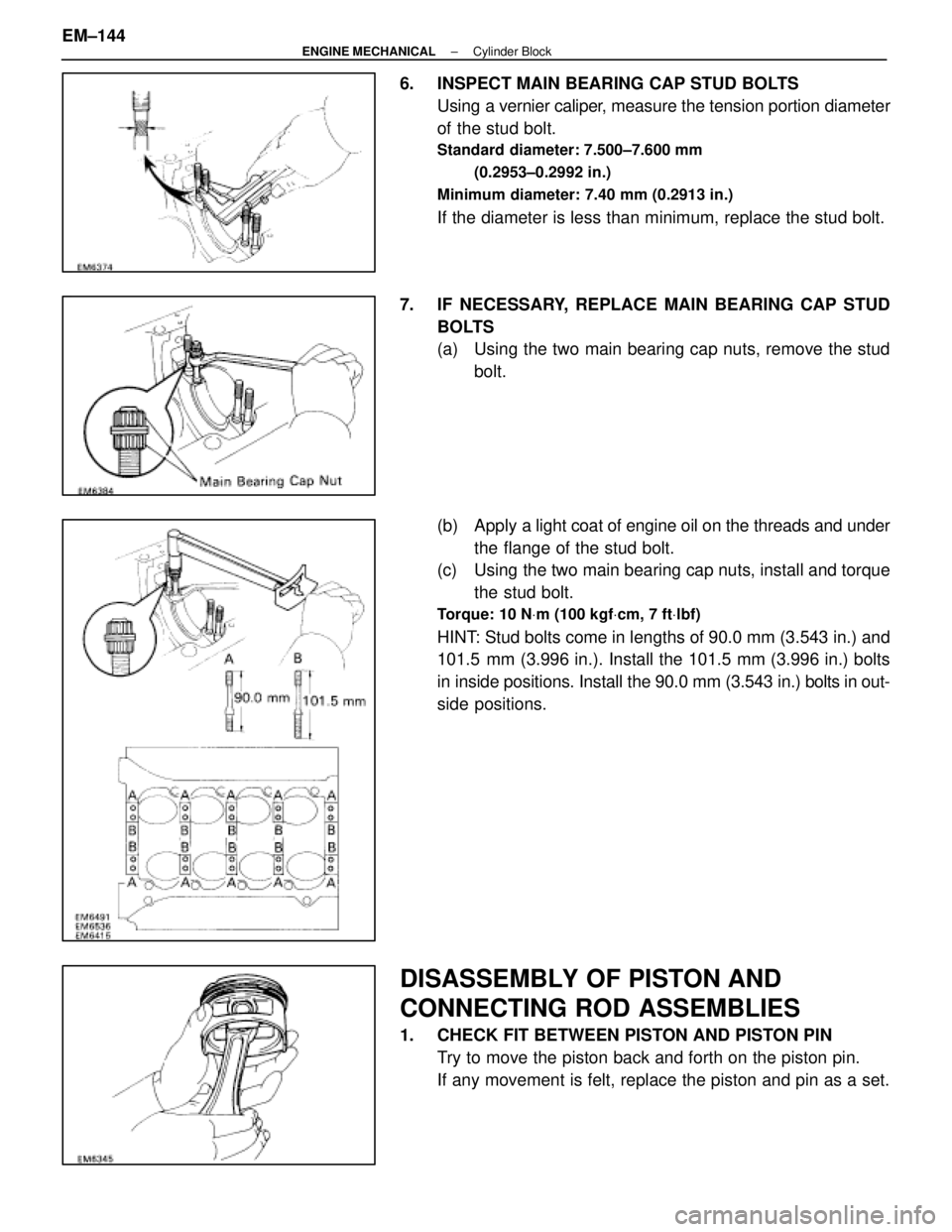
6. INSPECT MAIN BEARING CAP STUD BOLTSUsing a vernier caliper, measure the tension portion diameter
of the stud bolt.
Standard diameter: 7.500±7.600 mm
(0.2953±0.2992 in.)
Minimum diameter: 7.40 mm (0.2913 in.)
If the diameter is less than minimum, replace the stud bolt.
7. IF NECESSARY, REPLACE MAIN BEARING CAP STUD BOLTS
(a) Using the two main bearing cap nuts, remove the studbolt.
(b) Apply a light coat of engine oil on the threads and under
the flange of the stud bolt.
(c) Using the two main bearing cap nuts, install and torque
the stud bolt.
Torque: 10 N Vm (100 kgf Vcm, 7 ft Vlbf)
HINT: Stud bolts come in lengths of 90.0 mm (3.543 in.) and
101.5 mm (3.996 in.). Install the 101.5 mm (3.996 in.) bolts
in inside positions. Install the 90.0 mm (3.543 in.) bolts in out-
side positions.
DISASSEMBLY OF PISTON AND
CONNECTING ROD ASSEMBLIES
1. CHECK FIT BETWEEN PISTON AND PISTON PIN
Try to move the piston back and forth on the piston pin.
If any movement is felt, replace the piston and pin as a set.
EM±144
±
ENGINE MECHANICAL Cylinder Block
WhereEverybodyKnowsYourName
Page 1627 of 4087
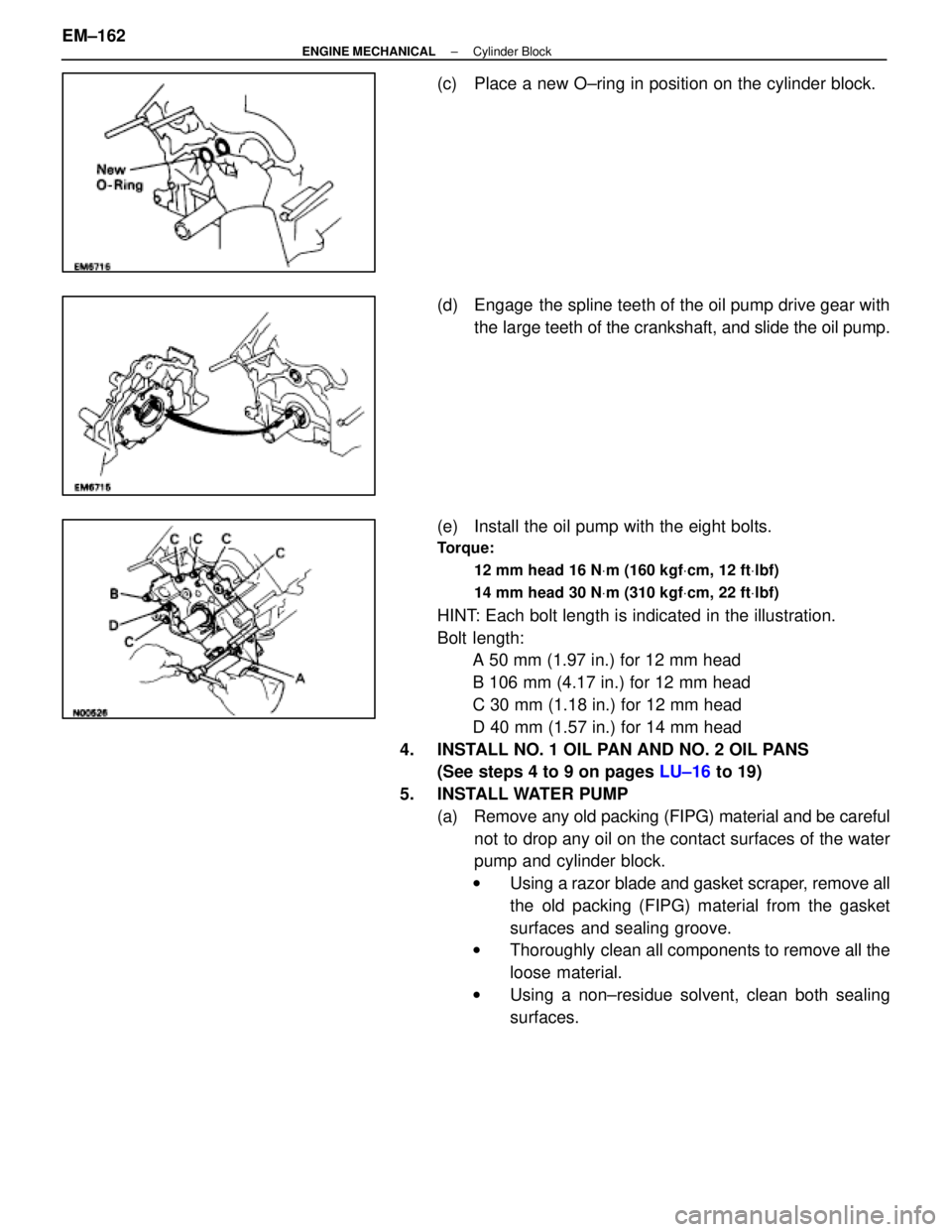
(c) Place a new O±ring in position on the cylinder block.
(d) Engage the spline teeth of the oil pump drive gear withthe large teeth of the crankshaft, and slide the oil pump.
(e) Install the oil pump with the eight bolts.
Torque: 12 mm head 16 N Vm (160 kgf Vcm, 12 ft Vlbf)
14 mm head 30 N Vm (310 kgf Vcm, 22 ft Vlbf)
HINT: Each bolt length is indicated in the illustration.
Bolt length:
A 50 mm (1.97 in.) for 12 mm head
B 106 mm (4.17 in.) for 12 mm head
C 30 mm (1.18 in.) for 12 mm head
D 40 mm (1.57 in.) for 14 mm head
4. INSTALL NO. 1 OIL PAN AND NO. 2 OIL PANS (See steps 4 to 9 on pages LU±16 to 19)
5. INSTALL WATER PUMP (a) Remove any old packing (FIPG) material and be carefulnot to drop any oil on the contact surfaces of the water
pump and cylinder block.
w Using a razor blade and gasket scraper, remove all
the old packing (FIPG) material from the gasket
surfaces and sealing groove.
w Thoroughly clean all components to remove all the
loose material.
w Using a non±residue solvent, clean both sealing
surfaces.
EM±162
±
ENGINE MECHANICAL Cylinder Block
WhereEverybodyKnowsYourName
Page 1628 of 4087
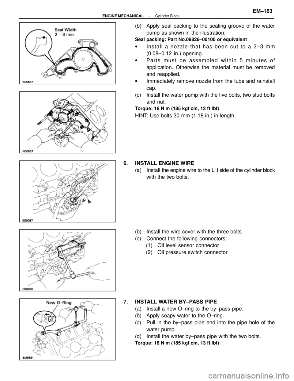
(b) Apply seal packing to the sealing groove of the waterpump as shown in the illustration.
Seal packing: Part No.08826±00100 or equivalent
wInstall a nozzle that has been cut to a 2±3 mm
(0.08±0.12 in.) opening.
w Parts must be assembled within 5 minutes of
application. Otherwise the material must be removed
and reapplied.
w Immediately remove nozzle from the tube and reinstall
cap.
(c) Install the water pump with the five bolts, two stud bolts and nut.
Torque: 18 N Vm (185 kgf Vcm, 13 ft Vlbf)
HINT: Use bolts 30 mm (1.18 in.) in length.
6. INSTALL ENGINE WIRE (a) Install the engine wire to the LH side of the cylinder block
with the two bolts.
(b) Install the wire cover with the three bolts.
(c) Connect the following connectors: (1) Oil level sensor connector
(2) Oil pressure switch connector
7. INSTALL WATER BY±PASS PIPE (a) Install a new O±ring to the by±pass pipe.
(b) Apply soapy water to the O±ring.
(c) Pull in the by±pass pipe end into the pipe hole of thewater pump.
(d) Install the water by±pass pipe with the two bolts.
Torque: 18 N Vm (185 kgf Vcm, 13 ft Vlbf)
±
ENGINE MECHANICAL Cylinder BlockEM±163
WhereEverybodyKnowsYourName