Page 415 of 1640
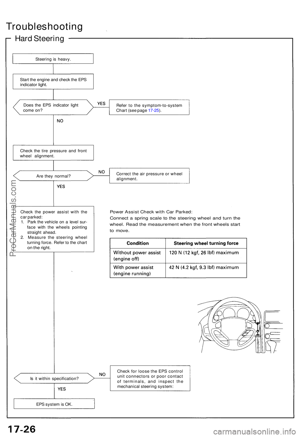
Steering Gearbo x
Motor an d Powe r Assis t Mechanis m
A moto r i s house d insid e th e gearbo x housing . I t consist s o f a yok e wit h a permanen t magne t fixe d i n it , a roto r wit h a
fiel d coil , an d brushe s whic h pas s electricit y t o roto r commutators . Th e moto r i s o n th e rac k shaf t o f th e steerin g gearbox .
Th e driv e curren t fro m th e contro l uni t flow s throug h th e powe r rela y an d fail-saf e rela y t o th e brushe s o f th e motor .
Th e driv e curren t flow s t o roto r commutator s throug h brushes , excitin g th e fiel d coi l o f th e roto r an d rotate s th e roto r wit h
th e magneti c actio n o f th e permanen t magne t insid e th e yoke . Th e roto r rotate s i n th e opposit e directio n whe n th e direc -
tio n o f driv e curren t i s reversed .
The rotatio n torqu e of th e moto r is transmitte d to th e bal l scre w through the helica l gear . The rotatio n torqu e on th e bal l
scre w is converte d int o assis t thrus t i n th e directio n o f steerin g rac k b y th e recirculatin g bal l screw . Th e mechanica l advan -
tag e o f th e recirculatin g bal l screw , compaire d t o a conventiona l rac k an d pinion , act s t o reduc e th e steerin g forc e t o th e
steerin g rac k throug h th e joint , t o lesse n th e steerin g effor t require d a t th e steerin g wheel .
ROTORRACK
RECIRCULATIN GBALL SCRE W
BAL L SCRE W
HELICA L GEA R
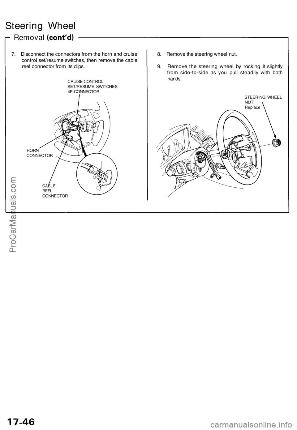
Recirculatin g Bal l Scre w
Th e recirculatin g bal l scre w is constructe d s o tha t stee l ball s rol l betwee n th e scre w shaf t an d th e nut , an d thos e comin g
ou t o f th e scre w fac e ente r th e scre w groov e agai n throug h a tub e fo r recirculation . Th e rotatio n torqu e o n th e shaf t i s
converte d int o thrus t i n a n axia l directio n a s th e slop e o f th e scre w shaf t presse s agains t th e nu t throug h th e stee l balls .
Sinc e th e torqu e conversio n i s mad e i n thi s metho d throug h th e scre w shaf t an d th e stee l balls , th e frictio n i s small , hig h
transmissio n efficienc y i s obtaine d fo r bot h th e forwar d an d backwar d directions , an d th e steerin g feel s identica l t o th e
ordinar y manua l steering .
Furthermore , sinc e th e forc e fro m th e backwar d directio n (forc e pressin g th e steerin g rack ) i s converte d int o th e rotatio n
torqu e o f th e scre w shaft , instantaneou s kick-bac k fro m th e roa d surfac e wil l rapidl y rotat e th e motor . I n suc h a rapi d rota -
tion , th e inerti a o f th e moto r increases , whic h act s t o reduc e th e kick-back . An y grea t kick-bac k wil l b e transmitte d fro m th e
steerin g rac k t o th e torqu e senso r o n th e pinion , whic h act s t o twis t th e pinio n shaf t i n th e sam e directio n a s th e inpu t
directio n o f kick-back . A s a result , th e moto r operate s th e kick-bac k to reduc e assis t force .
BALL SCRE W
TUBESTEE L BAL L
NUT
ProCarManuals.com
Page 424 of 1640
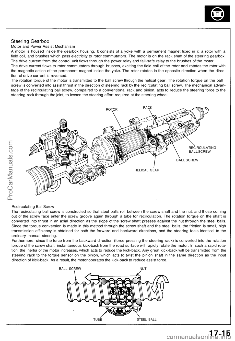
Troubleshooting
Hard Steerin g
Steering is heavy .
Star t th e engin e an d chec k th e EP S
indicato r light .
Does th e EP S indicato r ligh t
com e on ? Refe
r t o th e symptom-to-syste m
Char t (se e pag e 17-25 ).
Ar e the y normal ? Correc
t th e ai r pressur e o r whee l
alignment .
Chec k th e powe r assis t wit h th e
ca r parked :
1 . Par k th e vehicl e o n a leve l sur -
fac e wit h th e wheel s pointin g
straigh t ahead .
2 . Measur e th e steerin g whee l
turnin g force . Refe r t o th e char t
on th e right .
Powe r Assis t Chec k wit h Ca r Parked :
Connect a sprin g scal e t o th e steerin g whee l an d tur n th e
wheel . Rea d th e measuremen t whe n th e fron t wheel s star t
to move .
Is i t withi n specification ? Chec
k fo r loos e th e EP S contro l
uni t connector s o r poo r contac t
o f terminals , an d inspec t th e
mechanica l steerin g system :
EP S syste m is OK .
Chec
k th e tir e pressur e an d fron t
whee l alignment .
ProCarManuals.com
Page 425 of 1640
Inspection
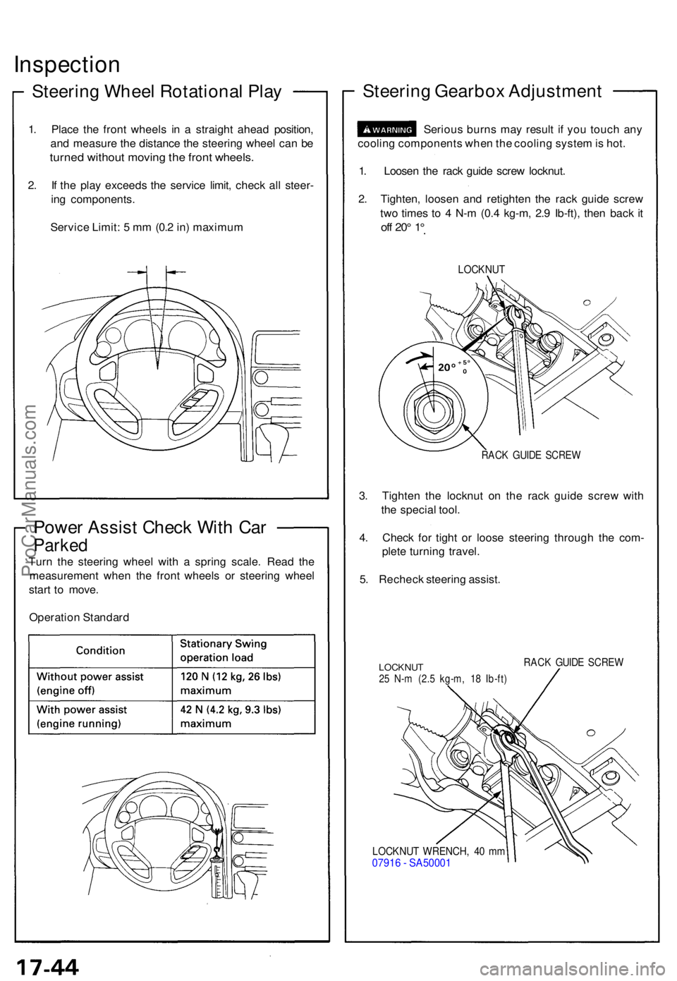
Steering Whee l Rotationa l Pla y
1. Plac e th e fron t wheel s i n a straigh t ahea d position ,
an d measur e th e distanc e th e steerin g whee l ca n b e
turne d withou t movin g th e fron t wheels .
2. I f th e pla y exceed s th e servic e limit , chec k al l steer -
in g components .
Servic e Limit : 5 m m (0. 2 in ) maximu m
Power Assis t Chec k Wit h Ca r
Parke d
Turn th e steerin g whee l wit h a sprin g scale . Rea d th e
measuremen t whe n th e fron t wheel s o r steerin g whee l
star t t o move .
Operatio n Standar d
Steering Gearbo x Adjustmen t
Serious burn s ma y resul t i f yo u touc h an y
coolin g component s whe n th e coolin g syste m is hot .
1 . Loose n th e rac k guid e scre w locknut .
2 . Tighten , loose n an d retighte n th e rac k guid e scre w
tw o time s t o 4 N- m (0. 4 kg-m , 2. 9 Ib-ft) , the n bac k i t
of f 20 ° 1 °
LOCKNU T
RACK GUID E SCRE W
3. Tighte n th e locknu t o n th e rac k guid e scre w wit h
th e specia l tool .
4 . Chec k fo r tigh t o r loos e steerin g throug h th e com -
plet e turnin g travel .
5 . Rechec k steerin g assist .
LOCKNU T25 N- m (2. 5 kg-m , 1 8 Ib-ft )
RACK GUID E SCRE W
LOCKNU T WRENCH , 4 0 m m0791 6 - SA5000 1
ProCarManuals.com
Page 426 of 1640
Steering Whee l
Remova l
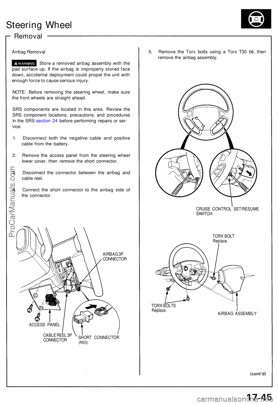
Airbag Remova l
Stor e a remove d airba g assembl y wit h th e
pa d surfac e up . I f th e airba g i s improperl y store d fac e
down , accidenta l deploymen t coul d prope l th e uni t wit h
enoug h forc e to caus e seriou s injury .
NOTE : Befor e removin g th e steerin g wheel , mak e sur e
th e fron t wheel s ar e straigh t ahead .
SR S component s ar e locate d i n thi s area . Revie w th e
SR S componen t locations , precautions , an d procedure s
i n th e SR S sectio n 24 befor e performin g repair s o r ser -
vice .
1 . Disconnec t bot h th e negativ e cabl e an d positiv e
cabl e fro m th e battery .
2 . Remov e th e acces s pane l fro m th e steerin g whee l
lowe r cover , the n remov e th e shor t connector .
3 . Disconnec t th e connecto r betwee n th e airba g an d
cabl e reel .
4 . Connec t th e shor t connecto r t o th e airba g sid e o f
th e connector .
AIRBAG 3P
CONNECTO R
ACCES S PANE L
CABL E REE L 3 P
CONNECTO RSHOR
T CONNECTO R
(RED)
5. Remov e th e Tor x bolt s usin g a Tor x T3 0 bit , the n
remov e th e airba g assembly .
TORX BOLT SReplace .
CRUISE CONTRO L SET/RESUM ESWITCH
TORX BOL TReplace .
AIRBAG ASSEMBL Y
ProCarManuals.com
Page 427 of 1640
Steering Wheel
Removal
7. Disconnect the connectors from the horn and cruise
control set/resume switches, then remove the cable
reel connector from its clips.
CRUISE CONTROL
SET/RESUME SWITCHES
4P CONNECTOR
HORN
CONNECTOR
CABLE
REEL
CONNECTOR
8. Remove the steering wheel nut.
9. Remove the steering wheel by rocking it slightly
from side-to-side as you pull steadily with both
hands.
STEERING WHEEL
NUT
Replace.ProCarManuals.com
Page 429 of 1640
Installation
NOTE: Before installing the steering wheel, make sure
the front wheels are straight ahead.
CAUTION:
• Be sure to install the harness wires so that they are
not pinched or interfering with other car parts.
• Do not replace the original steering wheel with any
other design, since it will make it impossible to prop-
erly install the airbag. (Use only genuine Honda
replacement parts.)
• After reassembly, confirm that the wheels are still
straight ahead and that steering wheel spoke angle
is correct. If minor spoke angle adjustment is neces-
sary, adjust the tie-rods only. Do not remove and
reposition the steering wheel.
Confirm that the airbag assembly is securely
attached to the steering wheel; otherwise, severe per-
sonal injury could result during later airbag deploy-
ment.
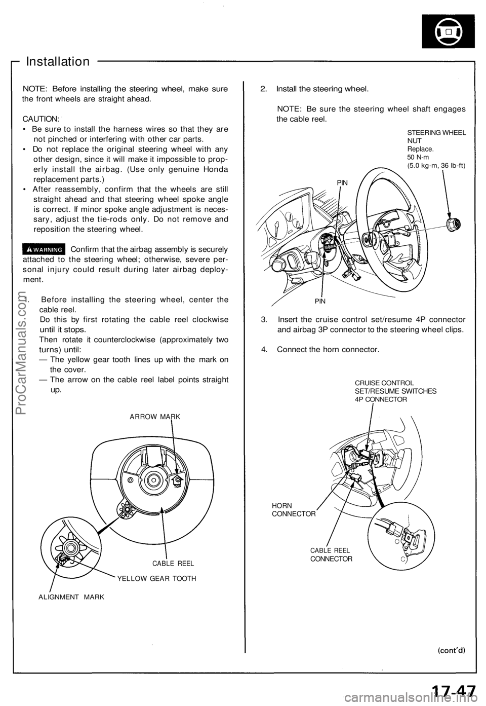
1. Before installing the steering wheel, center the
cable reel.
Do this by first rotating the cable reel clockwise
until it stops.
Then rotate it counterclockwise (approximately two
turns) until:
— The yellow gear tooth lines up with the mark on
the cover.
— The arrow on the cable reel label points straight
up.
ARROW MARK
CABLE REEL
YELLOW GEAR TOOTH
ALIGNMENT MARK
2. Install the steering wheel.
NOTE: Be sure the steering wheel shaft engages
the cable reel.
STEERING WHEEL
NUT
Replace.
50 N-m
(5.0 kg-m, 36 Ib-ft)
PIN
3. Insert the cruise control set/resume 4P connector
and airbag 3P connector to the steering wheel clips.
4. Connect the horn connector.
CRUISE CONTROL
SET/RESUME SWITCHES
4P CONNECTOR
HORN
CONNECTOR
CABLE REEL
CONNECTOR
PINProCarManuals.com
Page 430 of 1640
Steering Wheel
Installation
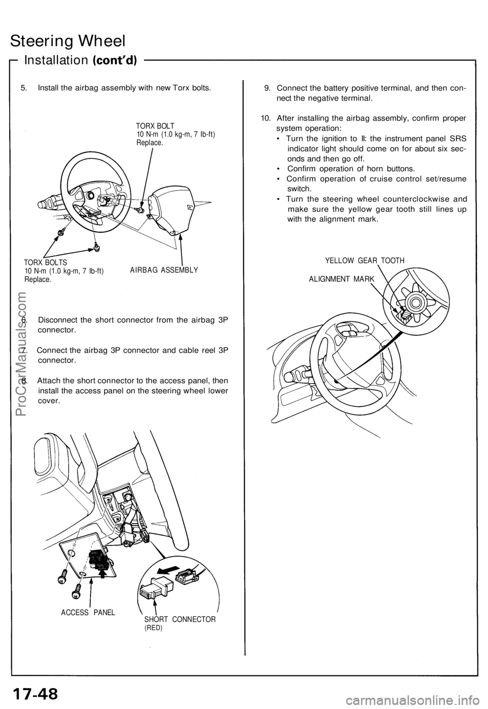
5. Install the airbag assembly with new Torx bolts.
TORX BOLT
10 N-m (1.0 kg-m, 7 Ib-ft)
Replace.
TORX BOLTS
10 N-m (1.0 kg-m, 7 Ib-ft)
Replace.
AIRBAG ASSEMBLY
6. Disconnect the short connector from the airbag 3P
connector.
7. Connect the airbag 3P connector and cable reel 3P
connector.
8. Attach the short connector to the access panel, then
install the access panel on the steering wheel lower
cover.
ACCESS PANEL
SHORT CONNECTOR
(RED)
9. Connect the battery positive terminal, and then con-
nect the negative terminal.
10. After installing the airbag assembly, confirm proper
system operation:
• Turn the ignition to II: the instrument panel SRS
indicator light should come on for about six sec-
onds and then go off.
• Confirm operation of horn buttons.
• Confirm operation of cruise control set/resume
switch.
• Turn the steering wheel counterclockwise and
make sure the yellow gear tooth still lines up
with the alignment mark.
YELLOW GEAR TOOTH
ALIGNMENT MARKProCarManuals.com
Page 437 of 1640
Steering Gearbox
Removal/Installation
NOTE: Before removing the steering gearbox, make
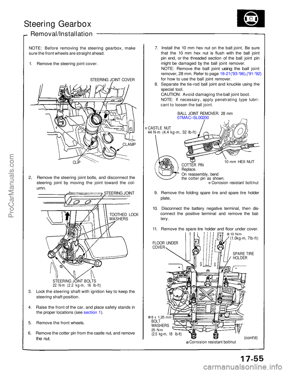
sure the front wheels are straight ahead. 1. Remove the steering joint cover.
STEERING JOINT COVER
7. Install the 10 mm hex nut on the balt joint. Be sure
that the 10 mm hex nut is flush with the ball joint
pin end, or the threaded section of the ball joint pin
might be damaged by the ball joint remover.
NOTE: Remove
the
ball
joint
using
the
ball
joint
remover, 28 mm. Refer to page 18-21('93-'96),('91-'92)
for how to use the ball joint remover.
8. Separate the tie-rod ball joint and knuckle using the
special tool.
CAUTION: Avoid damaging the ball joint boot.
NOTE: If necessary, apply penetrating type lubri-
cant to loosen the ball joint.
BALL JOINT REMOVER. 28 mm
07MAC–SL00200
CASTLE NUT
44 N·m (4.4 kg-m, 32 Ib-ft)
10 mm HEX NUT
CLAMP
CLIP
COTTER PIN
Replace.
On reassembly, bend
the cotter pin as shown.
Corrosion resistant bolt/nut
9. Remove the folding spare tire and spare tire holder plate,
10. Disconnect the battery negative terminal, then dis- connect the positive terminal and remove the bat-
tery.
11. Remove the spare tire holder and floor under cover.
FLOOR UNDER
COVER
10 N·m
(1.0kg-m, 7lb-ft)
SPARE TIRE
HOLDER
2, Remove the steering joint bolts, and disconnect the
steering joint by moving the joint toward the col-
umn.
STEERING JOINT
TOOTHED LOCK
WASHERS
STEERING JOINT BOLTS
22 N·m (2.2 kg-m, 16 Ib-ft)
3. Lock the steering shaft with ignition key to keep the steering shaft position.
4. Raise the front of the car, and place safety stands in the proper locations (see section 1).
5. Remove the front wheels.
6. Remove the cotter pin from the castle nut, and remove
the
nut.
8 x
1.25
mm
BOLT
WASHERS
25 N·m
(2.5 kg-m, 18 lb-ft)
Corrosion resistant bolt/nut
(cont'd)ProCarManuals.com