Page 292 of 1640
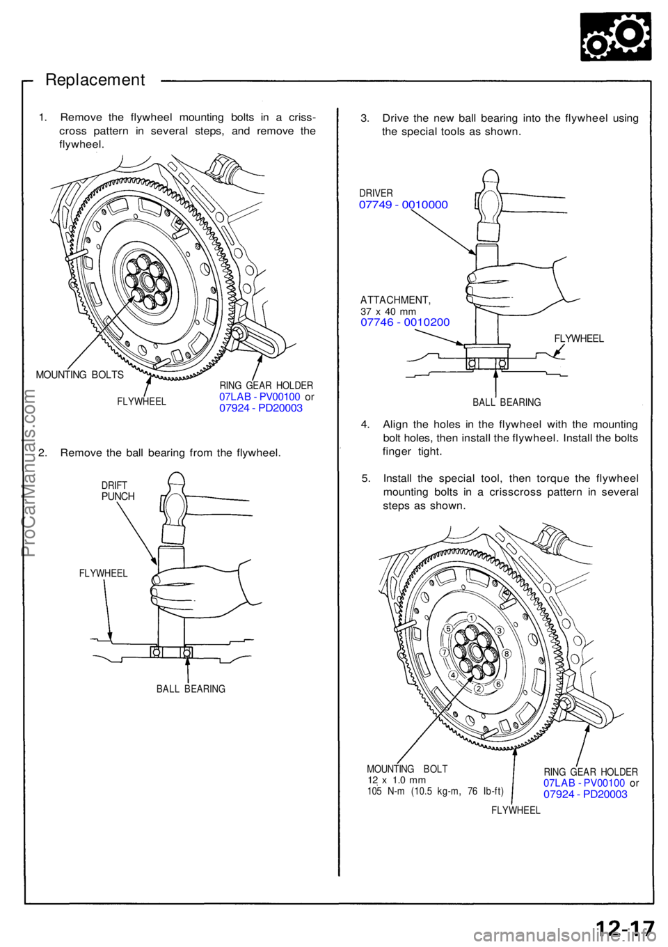
Mid Plate
Inspection
NOTE: If replacement is required, always replace the
pressure plate, mid plate, and flywheel as a set.
1. Inspect the mid plate surface for wear, cracks, and
burning.
2. Inspect for warpage using a straight edge andfeeler gauge.
NOTE: Measure across the mid plate at three points.
Standard: (New): 0.05 mm (0.002 in) max.
Service Limit: 0.15 mm (0.006 in)
STRAIGHT EDGE
MID PLATE
FEELERGAUGE
If the warpage is more than the service limit, replace
the mid plate.
After Pressing:
MID PLATE GUIDE
Before Pressing:
MID PLATE
The mid plate guides are the self-adjusting mechanisms
for the mid plate.
NOTE: Make sure all parts are clean before inspection.
Check the mid plate guides by pushing down on each of
the guides by hand (10–60 kg). The mid plate guides
should compress and lock in place.
If the mid plate guides do not move or compress, disas-
semble the mid plate guides and inspect them for debris,
wear and damage. Refer to page 12-15
('93-'96), 12-17
('91-'92 Models).
Inspection
Mid Plate GuideProCarManuals.com
Page 296 of 1640
Mid Plate Guide
Replacement (cont'd)
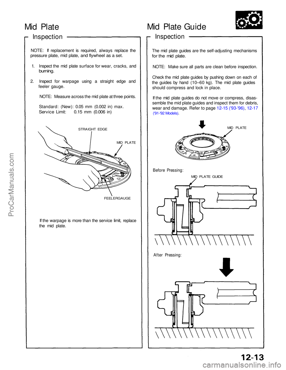
5. Install the new mid plate guide with the screw
installed.
MII D PLATE GUIDE
SCREW
MI D PLATE
6. Install the washer, spring and guide collar, then
remove the screw.
GUIDE COLLAR
SCREW SPRI
NG
WASHER
MID PLATE GUIDE
Install as shown.
7. Initialize the mid plate guides after installing the
clutch assembly (see page 12-14)
assembly Flywheel, Flywheel Bearing
Inspection
NOTE: If replacement is required, always replace the
pressure plate, mid plate, and flywheel as a set.
1. Inspect the ring gear teeth for wear and damage.
2. Inspect the clutch disc mating surface on the
flywheel for wear, cracks, and burning.
3. Measure the flywheel runout using a dial indicator through at least two full turns. Push against the
flywheel esch time you turn it to take up the
crankshaft thrust washer clearance.
NOTE: The runout can be measured with engine
installed.
Standard (New): 0.05 mm (0.002 in) max.
Service Limit: 0.15 mm (0.006 in)
If the runout exceeds the service limit, replace the
flywheel.
RING
GEAR
FLYWHEEL
4. Turn the inner race of the ball bearing with your
finger. The bearing should turn smoothly and quiet-
ly. Check that the bearing outer race fits tightly in
the flywheel. Replace the bearing if the race does
not turn smoothly, quietly, or fit tightly in the
flywheel.
BALL
BEARING
FLYWHEELProCarManuals.com
Page 297 of 1640
Replacement
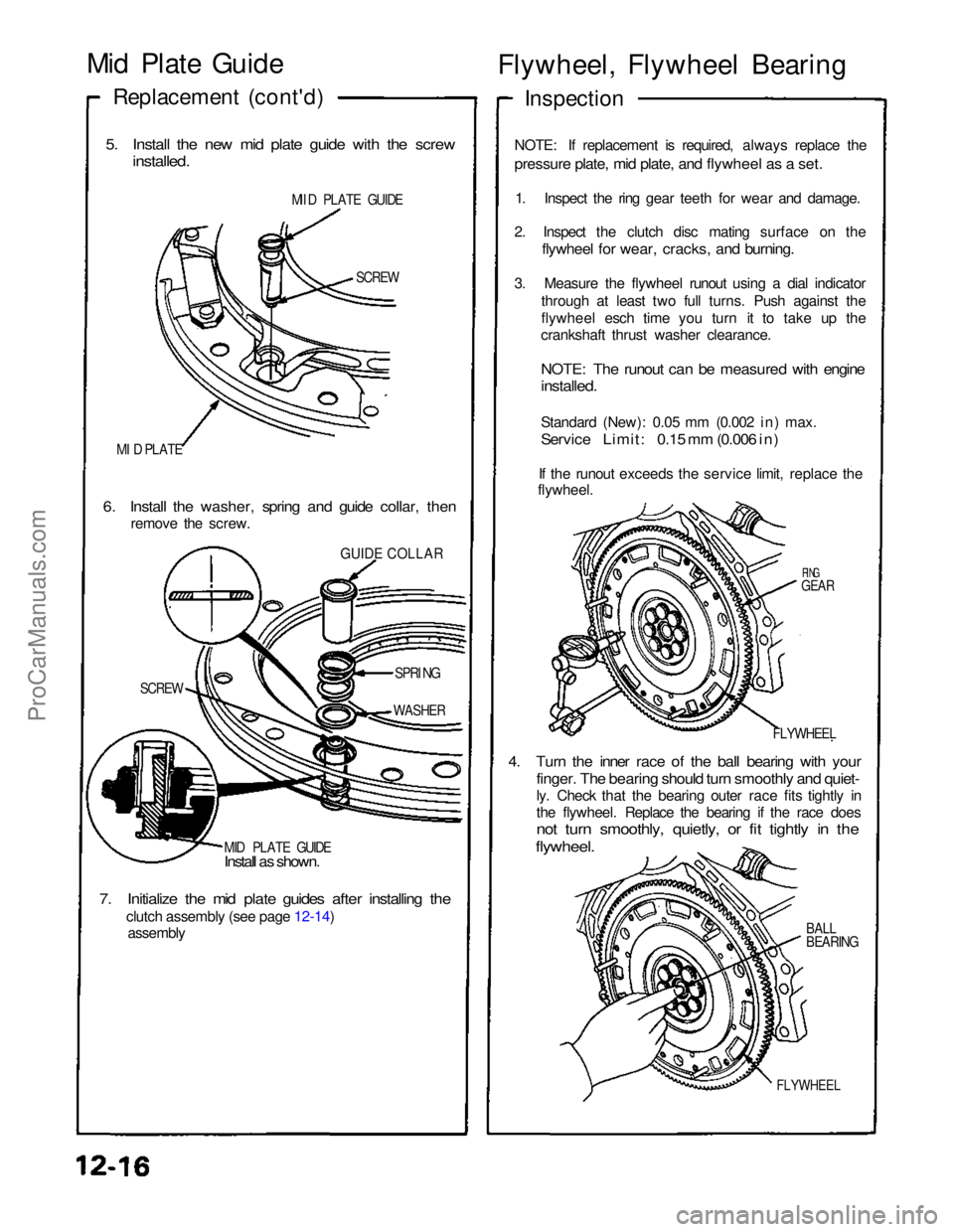
1. Remov e th e flywhee l mountin g bolt s i n a criss -
cros s patter n i n severa l steps , an d remov e th e
flywheel .
MOUNTIN G BOLT S
FLYWHEE L RIN
G GEA R HOLDE R07LAB - PV0010 0 o r0792 4 - PD2000 3
2 . Remov e th e bal l bearin g fro m th e flywheel .
DRIFTPUNC H
FLYWHEE L
BALL BEARIN G
3. Driv e th e ne w bal l bearin g int o th e flywhee l usin g
th e specia l tool s a s shown .
DRIVER07749 - 001000 0
ATTACHMENT ,37 x 40 m m07746 - 001020 0
FLYWHEEL
BALL BEARIN G
4. Alig n th e hole s i n th e flywhee l wit h th e mountin g
bol t holes , the n instal l th e flywheel . Instal l th e bolt s
finge r tight .
5 . Instal l th e specia l tool , the n torqu e th e flywhee l
mountin g bolt s i n a crisscros s patter n i n severa l
step s a s shown .
MOUNTIN G BOL T12 x 1. 0 m m105 N- m (10. 5 kg-m , 7 6 Ib-ft ) RIN
G GEA R HOLDE R07LAB - PV0010 0 o r0792 4 - PD2000 3
FLYWHEE L
ProCarManuals.com
Page 298 of 1640
Pressure Plate , Clutc h Dis c, Mid Plate
Installatio n
NOTE:
• Instal l th e pressur e plate , clutc h discs , an d mi d plat e
as a set .
• D o no t mix-u p th e 1s t an d 2n d clutc h discs . Th e 2n d
clutc h dis c ha s a fla t plat e betwee n th e tw o frictio n
surfaces . Th e 1s t clutc h dis c ha s a sprin g plat e be -
twee n th e tw o frictio n surfaces .
• Us e onl y Supe r Hig h Tem p Ure a Greas e (P/ N
08798-9002) .
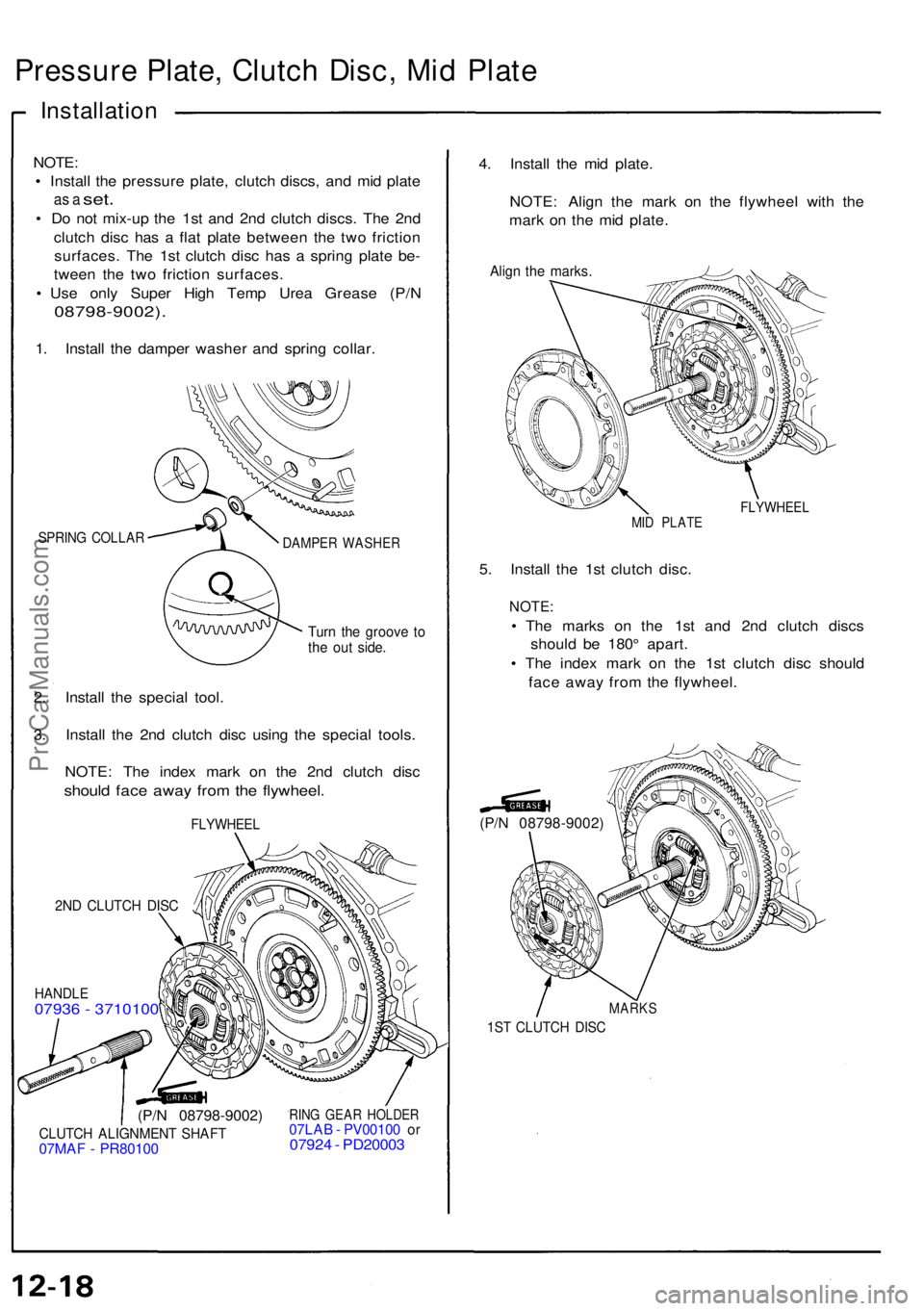
1. Instal l th e dampe r washe r an d sprin g collar .
SPRIN G COLLA RDAMPER WASHE R
Turn th e groov e t oth e ou t side .
2. Instal l th e specia l tool .
3 . Instal l th e 2n d clutc h dis c usin g th e specia l tools .
NOTE : Th e inde x mar k o n th e 2n d clutc h dis c
shoul d fac e awa y fro m th e flywheel .
FLYWHEE L
2ND CLUTC H DIS C
HANDL E07936 - 371010 0
(P/N 08798-9002 )
CLUTCH ALIGNMEN T SHAF T07MAF - PR8010 0
RING GEA R HOLDE R07LAB - PV0010 0 o r0792 4 - PD2000 3 4
. Instal l th e mi d plate .
NOTE : Alig n th e mar k o n th e flywhee l wit h th e
mar k o n th e mi d plate .
Align th e marks .
FLYWHEE LMID PLAT E
5. Instal l th e 1s t clutc h disc .
NOTE :
• Th e mark s o n th e 1s t an d 2n d clutc h disc s
shoul d b e 180 ° apart .
• Th e index mark o n th e 1s t clutc h dis c shoul d
fac e awa y fro m th e flywheel .
MARKS
1ST CLUTC H DIS C
(P/N 08798-9002 )
ProCarManuals.com
Page 306 of 1640
Transmission Assembly
Removal
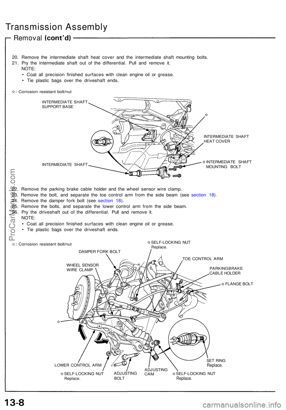
20. Remove the intermediate shaft heat cover and the intermediate shaft mounting bolts.
21. Pry the intermediate shaft out of the differential. Pull and remove it. NOTE:
• Coat all precision finished surfaces with clean engine oil or grease.
• Tie plastic bags over the driveshaft ends.
Corrosion resistant bolt/nut
INTERMEDIATE SHAFT
SUPPORT BASE
INTERMEDIATE SHAFT INTERMEDIATE SHAFT
HEAT COVER
INTERMEDIATE SHAFT
MOUNTING BOLT
22. Remove the parking brake cable holder and the wheel sensor wire clamp.
23. Remove the bolt, and separate the toe control arm from the side beam (see section 18).
24. Remove the damper fork bolt (see section 18).
25. Remove the bolts, and separate the lower control arm from the side beam. 26. Pry the driveshaft out of the differential. Pull and remove it. NOTE:
• Coat all precision finished surfaces with clean engine oil or grease.
• Tie plastic bags over the driveshaft ends.
Corrosion resistant bolt/nut
DAMPER FORK BOLT SELF-LOCKING NUT
Replace.
TOE CONTROL ARM
WHEEL SENSOR WIRE CLAMP PARKING BRAKE
CABLE HOLDER
FLANGE BOLT
LOWER CONTROL ARM SELF-LOCKING NUTReplace. ADJUSTING
BOLT
ADJUSTING
CAM
SELF-LOCKING NUT
Replace.
SET RING
Replace.ProCarManuals.com
Page 358 of 1640

Preset Torqu e
Inspectio n
On-Car:
1 . Bloc k th e fron t wheels .
2 . Shif t t o low gear .
3 . Lif t u p rea r wheels , an d plac e th e safet y stan d (Lif t
an d Suppor t Points , se e sectio n 1 ).
4 . Measur e prese t torqu e clockwis e usin g a torqu e
wrenc h a s shown .
Standard: 120-280 N-m (12-28 kg-m,
87-20 3 Ib-ft )
Servic e Limit : 6 0 N- m (6 kg-m , 4 3 Ib-ft )
TORQU E WRENC H
RIGH T REA R WHEE L
SAFETY STAN D
5. I f prese t torqu e is les s tha n th e servic e limit , replac e
th e limite d sli p differentia l clutc h set .
NOTE : Adjus t th e 6 5 m m (differentia l housin g cove r
side ) an d 11 2 m m (differentia l housin g cove r side )
shim s wheneve r th e clutc h se t i s replaced . Assembly
:
Plac e on e specia l too l i n a vise . Plac e th e lef t sid e
o f th e differentia l assembl y o n th e specia l tool , the n
prese t th e differentia l wit h 3- 5 rotations , counter -
clockwise .
DIFFERENTIA L
INSPECTIO N TOOL S
07MAJ-PR90100
2. Measur e prese t torqu e counterclockwis e usin g a tor -
qu e wrenc h a s shown.
Standard :
60-140 N- m (6-1 4 kg-m ,
43-10 1 Ib-ft )
Servic e Limit : 3 0 N- m (3 kg-m , 2 2 Ib-ft )
TORQU E WRENC H
DIFFERENTIA L
INSPECTIO N TOOL S
07MAJ-PR90100
3 . I f prese t torqu e is les s tha n th e servic e limit , replac e
th e limite d sli p differentia l clutc h set .
NOTE : Adjus t th e 6 5 m m an d 11 2 m m shim s
wheneve r th e clutc h se t i s replaced .
ProCarManuals.com
Page 373 of 1640
Preset Torque
Inspection
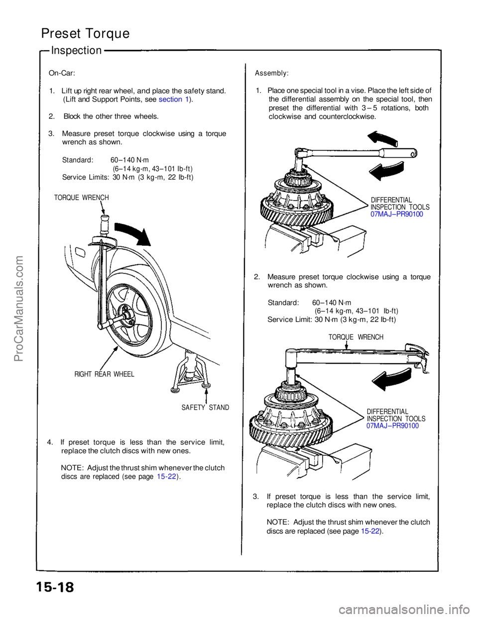
On-Car:
1. Lift up right rear wheel,
and place the safety stand.
(Lift and Support Points, see section 1).
2. Block the other three wheels.
3. Measure preset torque clockwise using a torque wrench as shown.
Standard:
60–140 N·m
(6–14 kg-m, 43–101 Ib-ft)
Service Limits: 30 N·m (3 kg-m, 22 Ib-ft)
TORQUE WRENCH
RIGHT REAR WHEEL SAFETY STAND
4. If preset torque is less than the service limit, replace the clutch discs with new ones.
NOTE: Adjust the thrust shim whenever the clutch
discs are replaced (see page 15-22).
Assembly:
1. Place one special tool in a vise. Place the left side of the differential assembly on the special tool, then
preset the differential with 3 – 5 rotations, both
clockwise and counterclockwise.
DIFFERENTIAL
INSPECTION TOOLS
07MAJ– PR90100
2. Measure preset torque clockwise using a torque wrench as shown.
Standard: 60–140 N·m
(6–14 kg-m, 43–101 Ib-ft)
Service Limit: 30 N·m (3 kg-m, 22 Ib-ft)
TORQUE WRENCH
DIFFERENTIAL
INSPECTION TOOLS
07MAJ – PR90100
3. If preset torque is less than the service limit, replace the clutch discs with new ones.
NOTE: Adjust the thrust shim whenever the clutch
discs are replaced (see page 15-22).
ProCarManuals.com
Page 387 of 1640
Driveshafts
Removal
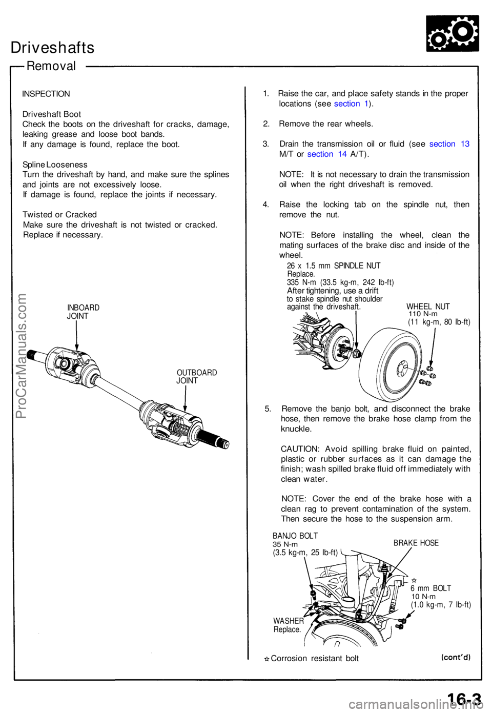
INSPECTIO N
Driveshaf t Boo t
Chec k th e boot s o n th e driveshaf t fo r cracks , damage ,
leakin g greas e an d loos e boo t bands .
I f an y damag e i s found , replac e th e boot .
Splin e Loosenes s
Tur n th e driveshaf t b y hand , an d mak e sur e th e spline s
an d joint s ar e no t excessivel y loose .
I f damag e i s found , replac e th e joint s i f necessary .
Twiste d o r Cracke d
Mak e sur e th e driveshaf t i s no t twiste d o r cracked .
Replac e if necessary .
INBOARDJOINT
OUTBOAR DJOINT
1. Rais e th e car , an d plac e safet y stand s in th e prope r
location s (se e sectio n 1 ).
2 . Remov e th e rea r wheels .
3 . Drai n th e transmissio n oi l o r flui d (se e sectio n 1 3
M/ T o r sectio n 1 4 A/T) .
NOTE : I t i s no t necessar y t o drai n th e transmissio n
oi l whe n th e righ t driveshaf t i s removed .
4 . Rais e th e lockin g ta b o n th e spindl e nut , the n
remov e th e nut .
NOTE : Befor e installin g th e wheel , clea n th e
matin g surface s of the brak e dis c an d insid e of the
wheel .
26 x 1. 5 m m SPINDL E NU TReplace .335 N- m (33. 5 kg-m , 24 2 Ib-ft )After tightening , us e a drif tto stak e spindl e nu t shoulde ragainst th e driveshaft . WHEE L NU T110 N- m(11 kg-m , 8 0 Ib-ft )
5. Remov e th e banj o bolt , an d disconnec t th e brak e
hose , the n remov e th e brak e hos e clam p fro m th e
knuckle .
CAUTION : Avoi d spillin g brak e flui d o n painted ,
plasti c o r rubbe r surface s a s i t ca n damag e th e
finish ; was h spille d brak e flui d of f immediatel y wit h
clea n water .
NOTE : Cove r th e en d o f th e brak e hos e wit h a
clea n ra g t o preven t contaminatio n of the system.
The n secur e th e hos e t o th e suspensio n arm .
BANJ O BOL T35 N- m(3.5 kg-m , 2 5 Ib-ft )
BRAK E HOS E
WASHE RReplace.
Corrosio n resistan t bol t
6 m m BOL T10 N- m(1.0 kg-m , 7 Ib-ft )
ProCarManuals.com