Page 612 of 1640
Replacement
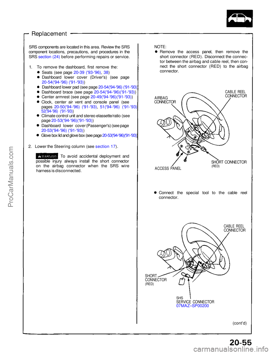
NOTE:
Remove the access panel, then remove the
short connector (RED). Disconnect the connec-
tor between the airbag and cable reel, then con-
nect the short connector (RED) to the airbag
connector.
AIRBAG
CONNECTOR
CABLE REEL
CONNECTOR
ACCESS PANEL
SHORT CONNECTOR
(RED)
Connect the special tool to the cable reel
connector.
CABLE REEL
CONNECTOR
SHORT
CONNECTOR
(RED)
SHS
SERVICE CONNECTOR
07MAZ–SP00200
(cont'd)
SRS components are located in this area. Review the SRS
component locations, precautions, and procedures in the
SRS section (24) before performing repairs or service.
1. To remove the dashboard, first remove the: Seats (see page 20-39 ('93-'96), 38)
Dashboard lower cover (Driver's) (see page
20-54('94-'96) ('91-'93))
Dashboard lower pad (see page 20-54('94-'96) ('91-'93))
Dashboard brace (see page 20-54('94-'96)('91-'93))
Cente
r
armrest (see page 20-49('94-'96)('91-'93))
Clock, center air vent and console panel (see
pages 20-50('94-'96) ('91-'93), 51('94-'96) ('91-'93)
52('94-'96) ('91-'93))
Climate control unit and stereo elassette/ratio (see
page 20-53('94-'96)('91-'93))
Dashboard lower cover (Passenger's) (see page
20-53('94-'96) ('91-'93))
Glove box lid and glove box (see page 20-53('94-'96)('91-'93))
2. Lower the Steering column (see section 17).
To avoid accidental deployment and
possible injury always install the short connector on the airbag connector when the SRS wire
harness is disconnected.ProCarManuals.com
Page 1011 of 1640
Installation
CAUTION: Do not rotate the crankshaft or camshaft without installing the belt. The piston could hit a valve
and damage may result.
1 . Install the timing belt in the reverse order of removal; Only keypoints are described here.
2 . Remove all spark plugs.
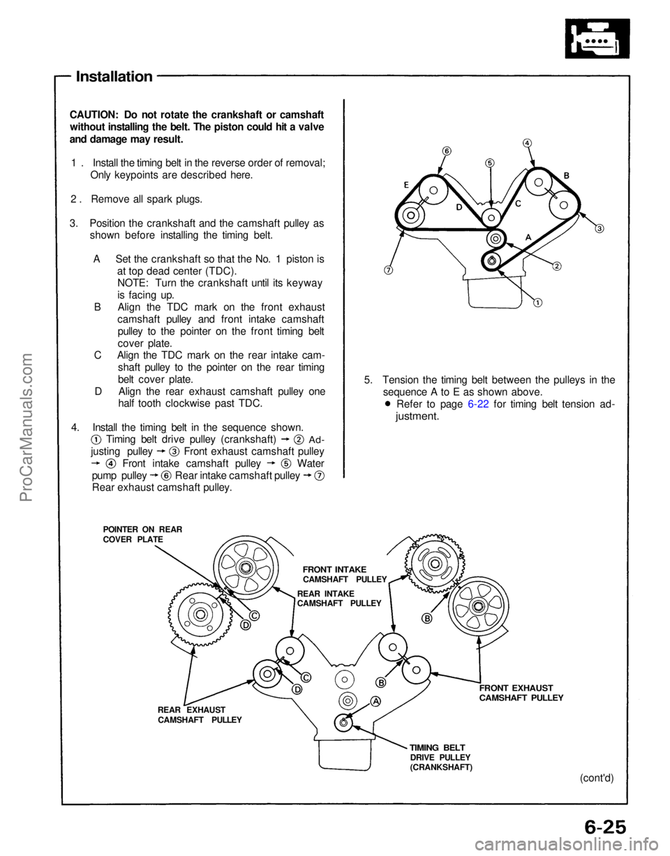
3. Position the crankshaft and the camshaft pulley as shown before installing the timing belt.
A Set the crankshaft so that the No. 1 piston is at top dead center (TDC).NOTE: Turn the crankshaft until its keyway
is facing up.
B Align the TDC mark on the front exhaust camshaft pulley and front intake camshaftpulley to the pointer on the front timing belt
cover plate.
C Align the TDC mark on the rear intake cam-
shaft pulley to the pointer on the rear timing
belt cover plate.
D Align the rear exhaust camshaft pulley one half tooth clockwise past TDC.
POINTER ON REAR
COVER PLATE
REAR EXHAUSTCAMSHAFT PULLEY
TIMING BELT
DRIVE PULLEY
(CRANKSHAFT)
FRONT EXHAUST
CAMSHAFT PULLEY
(cont'd)
5. Tension the timing belt between the pulleys in the
sequence A to E as shown above.
4. Install the timing belt in the sequence shown.
FRONT INTAKE
CAMSHAFT PULLEY
REAR INTAKE
CAMSHAFT PULLEY
Rear exhaust camshaft pulley.
Timing belt drive pulley (crankshaft)
Ad-
Water
justing pulley
Front intake camshaft pulley Front exhaust camshaft pulley
pump pulley Rear intake camshaft pulley Refer to page 6-22 for timing belt tension ad-
justment.ProCarManuals.com
Page 1041 of 1640
Valve Clearance
Adjustment
Valves should be adjusted cold when the cylinder head
temperature is less than 100°F (38°C).
Adjustment is the same for both intake and exhaust
valves.
Adjust valve clearance at TDC of each cylinder.
Do not rotate the engine counterclockwise. The tim-
ing belt could jump a tooth on the camshaft pulleys.
EXHAUST
INTAKE
INTAKE
EXHAUST
TDC MARK (WHITE PAINT)
CRANKSHAFT PULLEY
POINTER ON
THE LOWER
COVER
TDC mark (white paint) on the crank pulley should
align with pointer on the timing lower cover, and
TDC grooves on the camshaft pulleys should align
with timing belt cover plates.
FRONT:
No.1 PISTON at TDC
REAR:
NOTE:
1. Remove the cylinder head covers.
FRONT:
REAR:
2. Rotate crankshaft and set No.1 piston at TDC.ProCarManuals.com
Page 1079 of 1640
II. ENGINE CONTROL MODULE (ECM) Reset Procedure
1. Turn the ignition switch off.
2. Remove the CLOCK (7.5 A) fuse from the under-hood fuse/relay box for 10 seconds to reset ECM.
NOTE: Disconnecting the CLOCK fuse also cancels the radio preset stations and the clock setting. Make note of
the radio presets before removing the fuse so you can reset them.
III. Final Procedure (this procedure must be done after any troubleshooting)
1. Remove the Jumper Wire.
NOTE: If the Service Check Connector is jumped, the MIL will stay on.
2. Do the ECM Reset Procedure.
3. Set the radio preset stations and the clock setting.
(cont'd)
CLOCK
(7.5 A) FUSE
UNDER-HOOD
FUSE/RELAY BOXProCarManuals.com
Page 1106 of 1640
Idle Control System
Idle Speed Setting
Inspection/Adjustment NOTE: (Canada) Pull the parking brake lever up.
Start the engine, then check that the head lights
are
off.
1. Start the engine and warm it up to normal operating temperature (the cooling fan comes on).
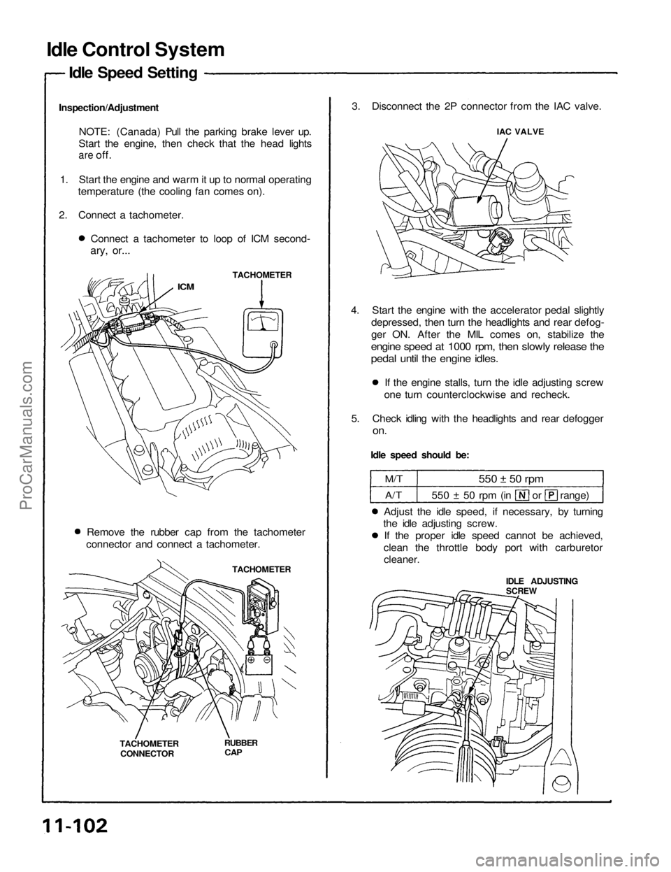
2. Connect a tachometer. Connect a tachometer to loop of ICM second-
ary, or...
TACHOMETER
ICM
Remove the rubber cap from the tachometer
connector and connect a tachometer.
TACHOMETER
TACHOMETER CONNECTOR
RUBBER
CAP
3. Disconnect the 2P connector from the IAC valve.
IAC VALVE
4. Start the engine with the accelerator pedal slightly depressed, then turn the headlights and rear defog-
ger ON. After the MIL comes on, stabilize the
engine speed at 1000 rpm, then slowly release the
pedal until the engine idles.
If the engine stalls, turn the idle adjusting screw
one turn counterclockwise and recheck.
5. Check idling with the headlights and rear defogger
on.
Idle speed should be:
M/T
A/T
550 ± 50 rpm
550 ± 50 rpm (in or range)
Adjust the idle speed, if necessary, by turning
the idle adjusting screw.
If the proper idle speed cannot be achieved,
clean the throttle body port with carburetor
cleaner.
IDLE ADJUSTING
SCREWProCarManuals.com
Page 1107 of 1640
6. Turn the ignition switch OFF.
7. Reconnect the 2P connector on the IAC valve, then
remove CLOCK fuse in the under-hood fuse/relay
box for 10 seconds to reset ECM.
8. Restart and idle the engine with no-load conditions
in which the headlights, blower fan, rear defogger,
cooling fan, and air conditioner are not operating
for one minute, then check the idle speed.
Idle speed should be:
M/T
A/T
800
50 rpm
750
50 rpm
(in or range)ProCarManuals.com
Page 1208 of 1640
Troubleshooting Procedures
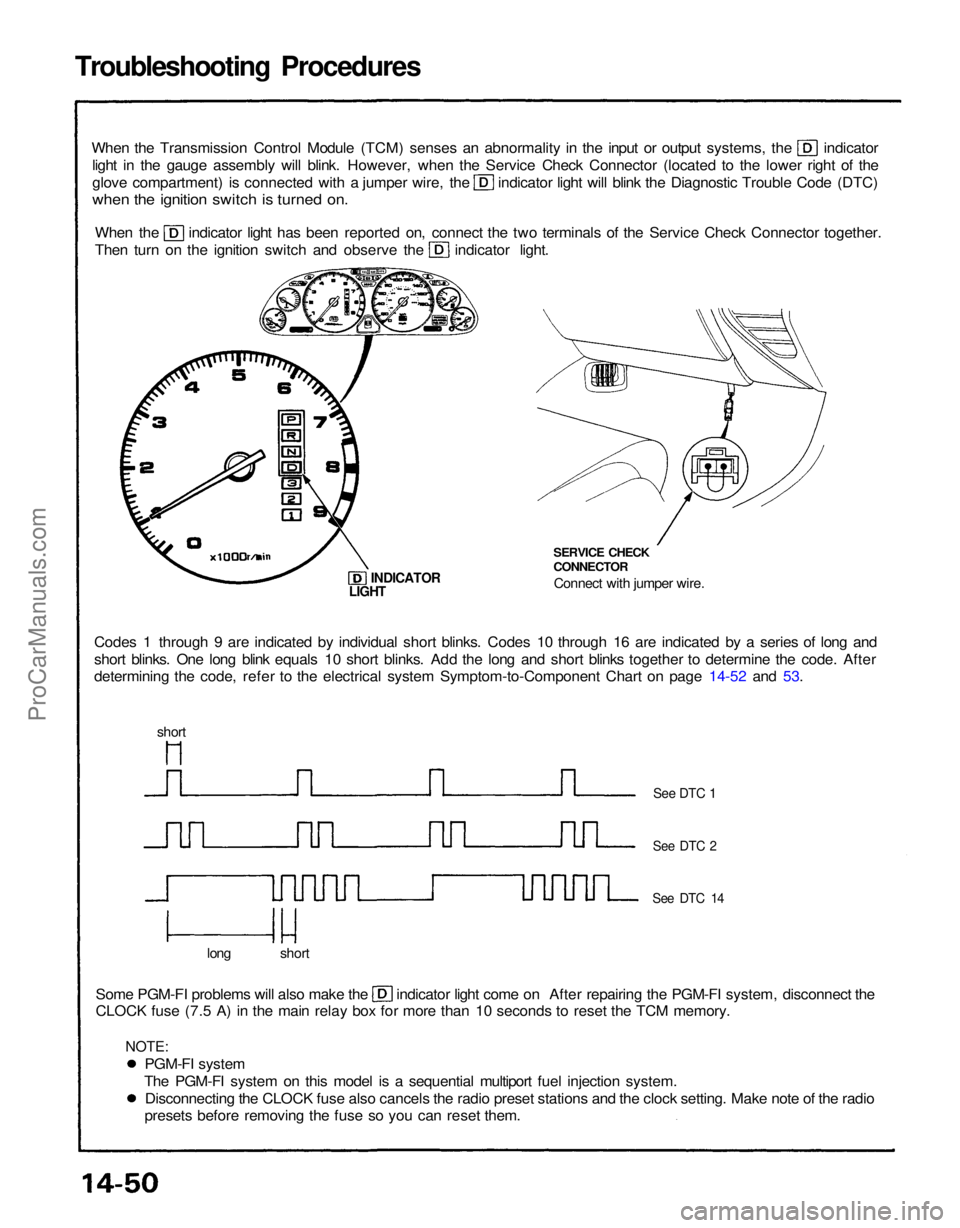
When the Transmission Control Module (TCM) senses an abnormality in the input or output systems, the indicator
light in the gauge assembly will blink. However, when the Service Check Connector (located to the lower right of the glove compartment) is connected with a jumper wire, the indicator light will blink the Diagnostic Trouble Code (DTC)
when the ignition switch is turned on.
When the indicator light has been reported on, connect the two terminals of the Service Check Connector together.
Then turn on the ignition switch and observe the indicator light.
Codes 1 through 9 are indicated by individual short blinks. Codes 10 through 16 are indicated by a series of long and
short blinks. One long blink equals 10 short blinks. Add the long and short blinks together to determine the code. After
determining the code, refer to the electrical system Symptom-to-Component Chart on page 14-52 and 53. SERVICE CHECK
CONNECTOR
Connect with jumper wire.
INDICATOR
Some PGM-FI problems will also make the indicator light come on After repairing the PGM-FI system, disconnect the
CLOCK fuse (7.5 A) in the main relay box for more than 10 seconds to reset the TCM memory.
long short
See DTC 1
See DTC 2
See DTC 14
LIGHT
short
PGM-FI system
The PGM-FI system on this model is a sequential multiport fuel injection system. Disconnecting the CLOCK fuse also cancels the radio preset stations and the clock setting. Make note of the radio
presets before removing the fuse so you can reset them.
NOTE:ProCarManuals.com
Page 1209 of 1640
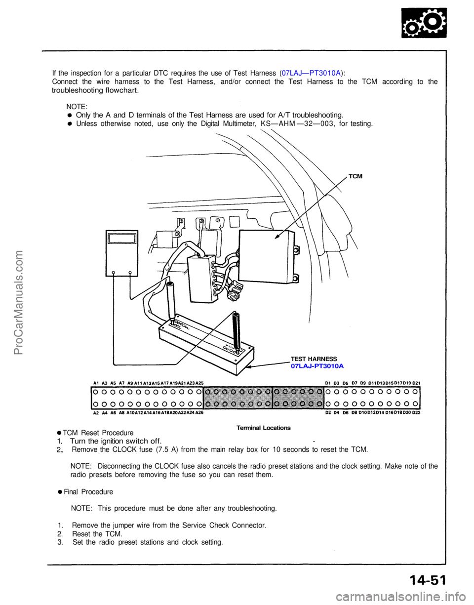
If the inspection for a particular DTC requires the use of Test Harness (07LAJ—PT3010A):
Connect the wire harness to the Test Harness, and/or connect the Test Harness to the TCM according to the
troubleshooting flowchart.
TCM
TEST HARNESS
Terminal Locations
TCM Reset Procedure
Turn the ignition switch off. -
, Remove the CLOCK fuse (7.5 A) from the main relay box for 10 seconds to reset the TCM.
1
2
NOTE: Disconnecting the CLOCK fuse also cancels the radio preset stations and the clock setting. Make note of the
radio presets before removing the fuse so you can reset them.
Final Procedure NOTE: This procedure must be done after any troubleshooting.
1. Remove the jumper wire from the Service Check Connector.
2. Reset the TCM. 3. Set the radio preset stations and clock setting.
Only the A and D terminals of the Test Harness are used for A/T troubleshooting.
Unless otherwise noted, use only the Digital Multimeter, KS—AHM —32—003, for testing.
07LAJ-PT3010A
NOTE:ProCarManuals.com