1991 ACURA NSX set clock
[x] Cancel search: set clockPage 1211 of 1640
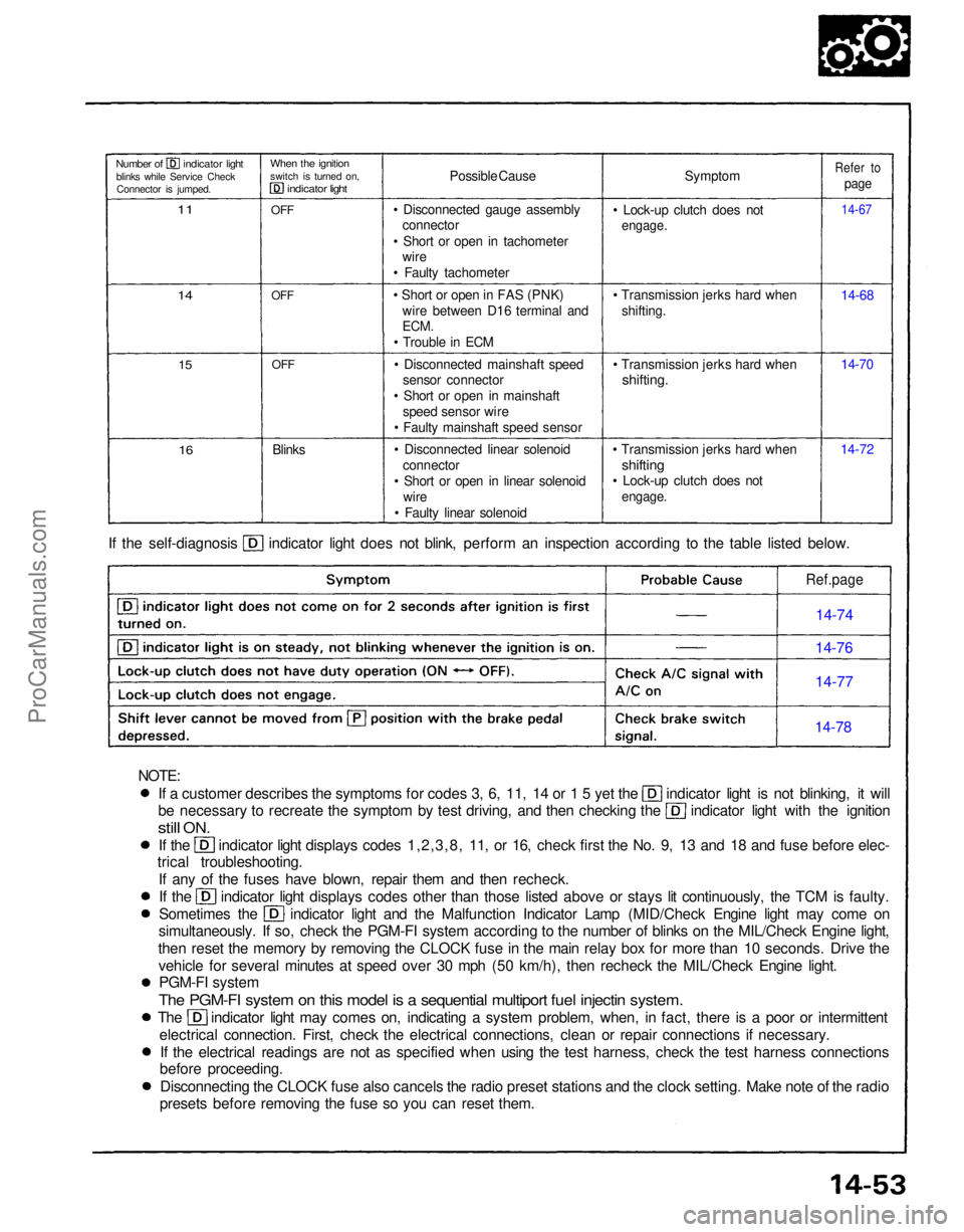
If a customer describes the symptoms for codes 3, 6, 11, 14 or 1 5 yet the indicator light is not blinking, it will
be necessary to recreate the symptom by test driving, and then checking the indicator light with the ignition
still
ON.
If the indicator light displays codes 1,2,3,8, 11, or 16, check first the No. 9, 13 and 18 and fuse before elec-
trical troubleshooting.
If any of the fuses have blown, repair them and then recheck. If the indicator light displays codes other than those listed above or stays lit continuously, the TCM is faulty.
Sometimes the indicator light and the Malfunction Indicator Lamp (MID/Check Engine light may come on
simultaneously. If so, check the PGM-FI system according to the number of blinks on the MIL/Check Engine light,
then reset the memory by removing the CLOCK fuse in the main relay box for more than 10 seconds. Drive the vehicle for several minutes at speed over 30 mph (50 km/h), then recheck the MIL/Check Engine light.PGM-FI system
The PGM-FI system on this model is a sequential multiport fuel injectin system.
The indicator light may comes on, indicating a system problem, when, in fact, there is a poor or intermittent
electrical connection. First, check the electrical connections, clean or repair connections if necessary.If the electrical readings are not as specified when using the test harness, check the test harness connections
before proceeding.
Disconnecting the CLOCK fuse also cancels the radio preset stations and the clock setting. Make note of the radio
presets before removing the fuse so you can reset them. If the self-diagnosis indicator light does not blink, perform an inspection according to the table listed below.
Symptom
• Lock-up clutch does not
engage.
• Transmission jerks hard when shifting.
• Transmission jerks hard when
shifting.
• Transmission jerks hard when
shifting
• Lock-up clutch does not
engage.
14-7214-70 14-68
14-67
Refer to
page
Possible Cause
• Disconnected gauge assembly connector
• Short or open in tachometer wire
• Faulty tachometer
• Short or open in FAS (PNK) wire between D16 terminal and
ECM.
• Trouble in ECM
• Disconnected mainshaft speed sensor connector
• Short or open in mainshaft speed sensor wire
• Faulty mainshaft speed sensor
• Disconnected linear solenoid connector
• Short or open in linear solenoid wire
• Faulty linear solenoid
Blinks
OFF
OFF
OFF
When the ignition
switch is turned on,
indicator light
Number of indicator light
blinks while Service CheckConnector is jumped.
11
14
15
16
Ref.page
14-74
14-76
14-77
14-78
NOTE:ProCarManuals.com
Page 1303 of 1640
Steering Wheel
Installation
NOTE: Before installing the steering wheel, make sure
the front wheels are straight ahead.
CAUTION:
Be sure to install the harness wires so that they are
not pinched or interfering with other car parts.
Do not replace the original steering wheel with any
other design, since it will make it impossible to proper-
ly install the airbag. (Use only genuine HONDA
replacement parts.)
After reassembly, confirm that the wheels are still
straight ahead and that steering wheel spoke angle
is correct. If minor spoke angle adjustment is neces-
sary, adjust the tie-rods only. Do not remove and
reposition the steering wheel.
Confirm that the airbag assembly is secure-
ly attached to the steering wheel; otherwise, severe per-
sonal injury could result during later airbag deployment.
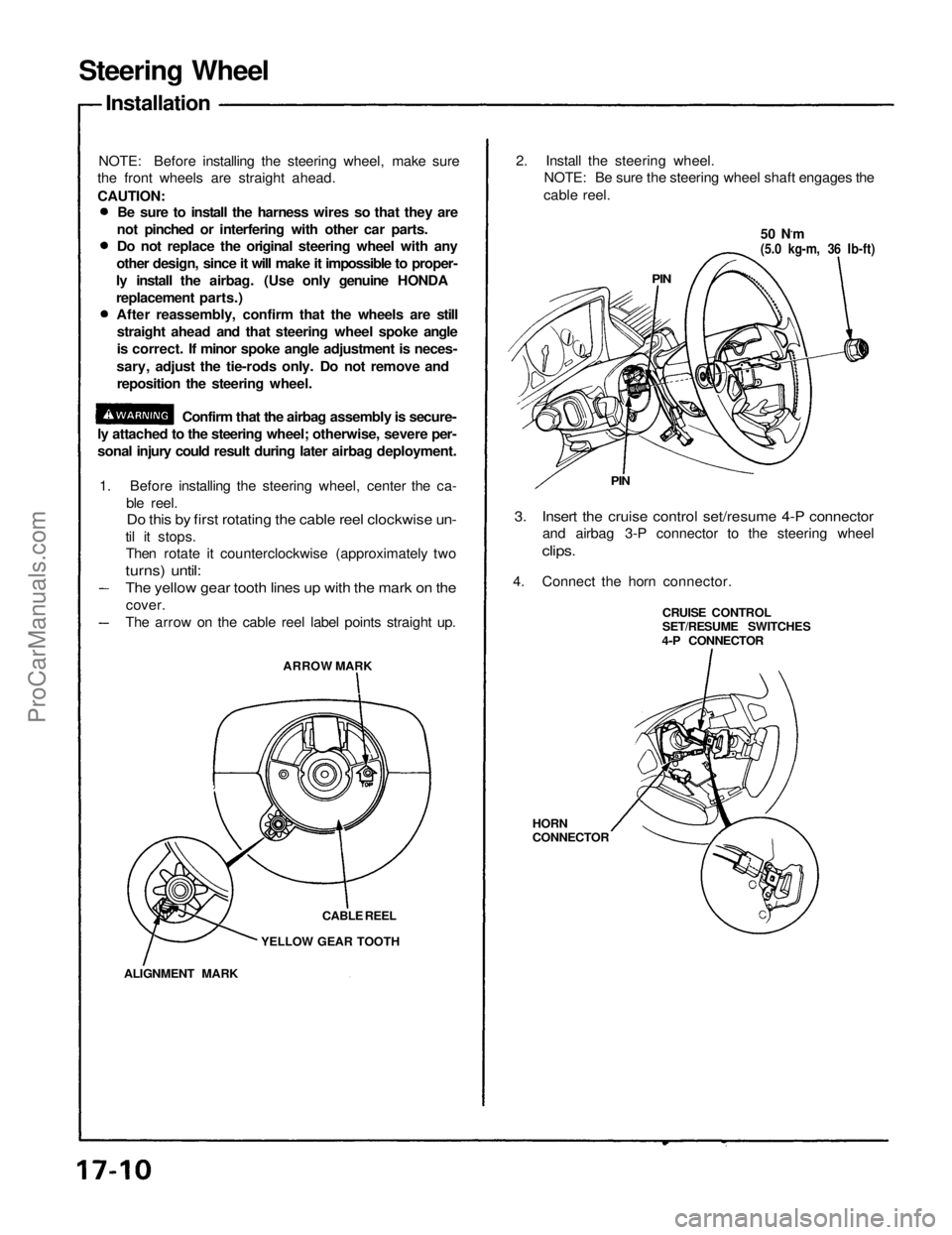
1. Before installing the steering wheel, center the ca-
ble reel.
Do this by first rotating the cable reel clockwise un-
til it stops.
Then rotate it counterclockwise (approximately two
turns) until:
ARROW MARK
CABLE REEL
YELLOW GEAR TOOTH
ALIGNMENT MARK
2. Install the steering wheel.
NOTE: Be sure the steering wheel shaft engages the
cable reel.
50 N.m
(5.0 kg-m, 36 Ib-ft)
PIN
PIN
3. Insert the cruise control set/resume 4-P connector
and airbag 3-P connector to the steering wheel
clips.
4. Connect the horn connector.
CRUISE CONTROL
SET/RESUME SWITCHES
4-P CONNECTOR
HORN
CONNECTOR
The yellow gear tooth lines up with the mark on the
cover.
The arrow on the cable reel label points straight up.ProCarManuals.com
Page 1304 of 1640
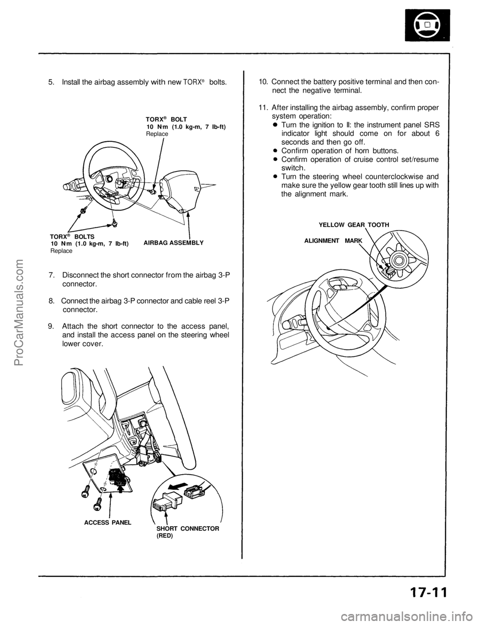
5.
Install
the
airbag assembly
with
new
TORX
®
bolts.
TORX ®
BOLT
10 N ·
m (1.0 kg-m, 7 Ib-ft)
Replace
TORX ®
BOLTS
10 N ·
m (1.0 kg-m, 7 Ib-ft)
Replace
AIRBAG ASSEMBLY
7. Disconnect the short connector from the airbag 3-P connector.
8. Connect the airbag 3-P connector and cable reel 3-P
connector.
9. Attach the short connector to the access panel, and install the access panel on the steering wheel
lower cover.
ACCESS PANEL SHORT CONNECTOR
(RED)
10. Connect the battery positive terminal and then con-
nect the negative terminal.
11. After installing the airbag assembly, confirm proper system operation:
Turn the ignition to II: the instrument panel SRSindicator light should come on for about 6
seconds and then go off.
Confirm operation of horn buttons.
Confirm operation of cruise control set/resume
switch.
Turn the steering wheel counterclockwise and
make sure the yellow gear tooth still lines up with
the alignment mark.
YELLOW GEAR TOOTH
ALIGNMENT MARKProCarManuals.com
Page 1336 of 1640
Troubleshooting
Diagnostic Trouble Code (DTC) Display
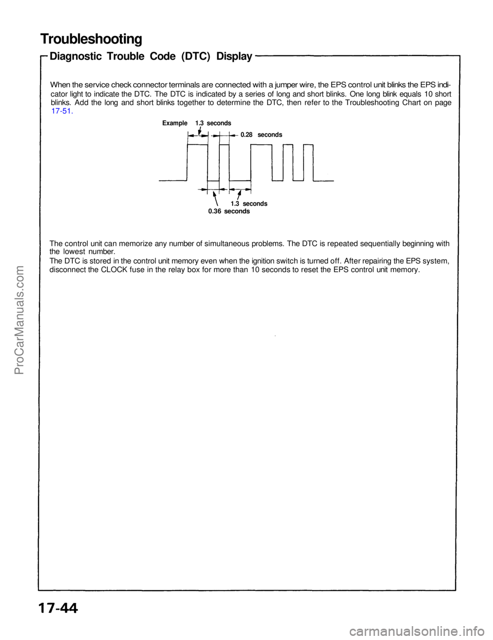
When the service check connector terminals are connected with a jumper wire, the EPS control unit blinks the EPS indi-
cator light to indicate the DTC. The DTC is indicated by a series of long and short blinks. One long blink equals 10 shortblinks. Add the long and short blinks together to determine the DTC, then refer to the Troubleshooting Chart on page 17-51.
Example 1.3 seconds
0.28 seconds
1.3 seconds
0.36 seconds
The control unit can memorize any number of simultaneous problems. The DTC is repeated sequentially beginning with
the lowest number.
The DTC is stored in the control unit memory even when the ignition switch is turned off. After repairing the EPS system,
disconnect the CLOCK fuse in the relay box for more than 10 seconds to reset the EPS control unit memory.ProCarManuals.com
Page 1374 of 1640
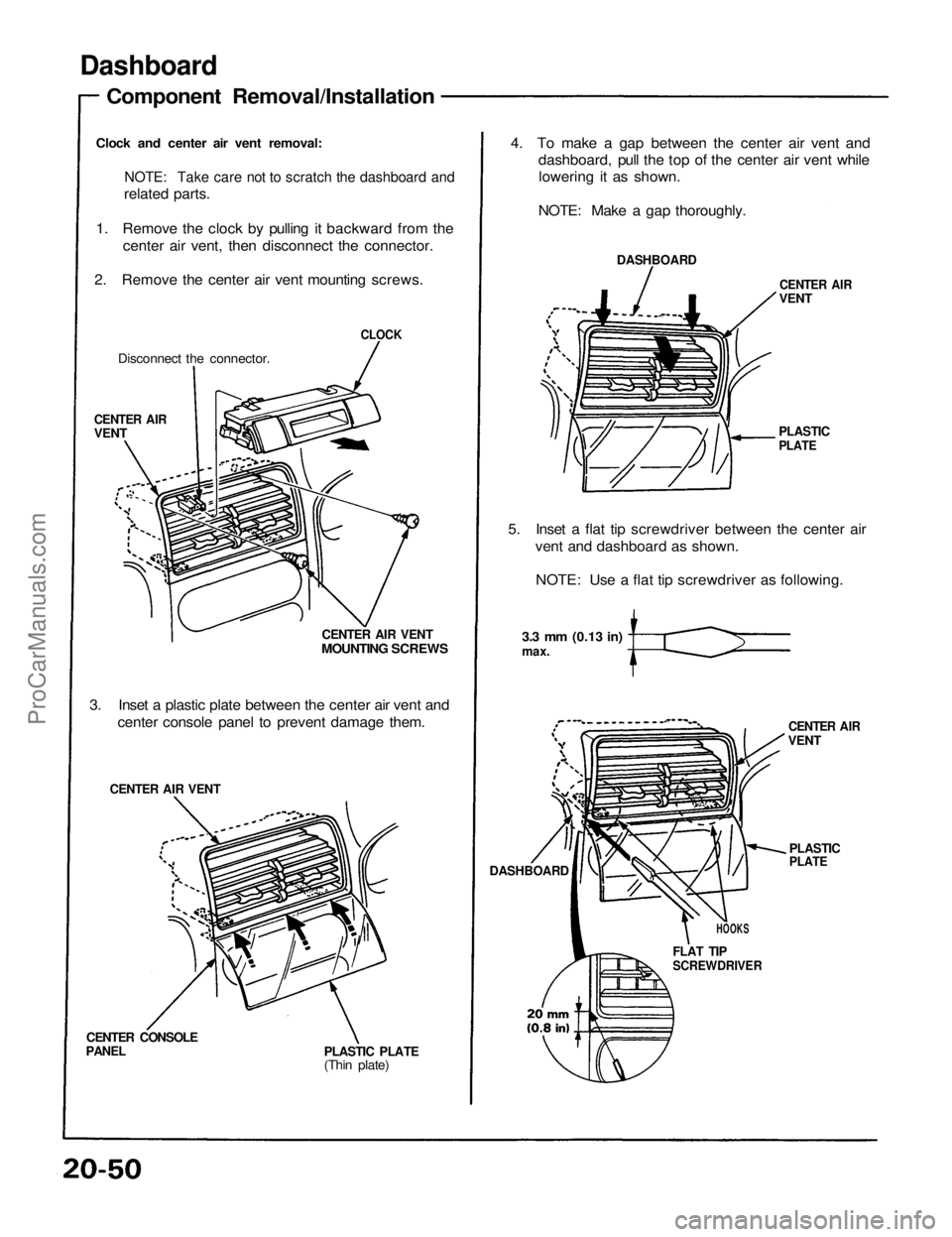
Dashboard
Component Removal/Installation
Clock and center air vent removal:
NOTE: Take care not to scratch the dashboard and
related parts.
1. Remove the clock by pulling it backward from the center air vent, then disconnect the connector.
2. Remove the center air vent mounting screws.
Disconnect the connector.
CLOCK
CENTER AIR
VENT
CENTER AIR VENT
MOUNTING SCREWS
3. Inset a plastic plate between the center air vent and center console panel to prevent damage them.
CENTER AIR VENT
CENTER CONSOLE
PANEL
PLASTIC PLATE
(Thin plate)4. To make a gap between the center air vent and
dashboard, pull the top of the center air vent whilelowering it as shown.
NOTE: Make a gap thoroughly.
DASHBOARD
CENTER AIR
VENT
PLASTIC
PLATE
5. Inset a flat tip screwdriver between the center air vent and dashboard as shown.
NOTE: Use a flat tip screwdriver as following.
3.3 mm
(0.13
in)
max.
CENTER AIR
VENT
DASHBOARD
PLASTIC
PLATE
HOOKS
FLAT TIP
SCREWDRIVERProCarManuals.com
Page 1375 of 1640
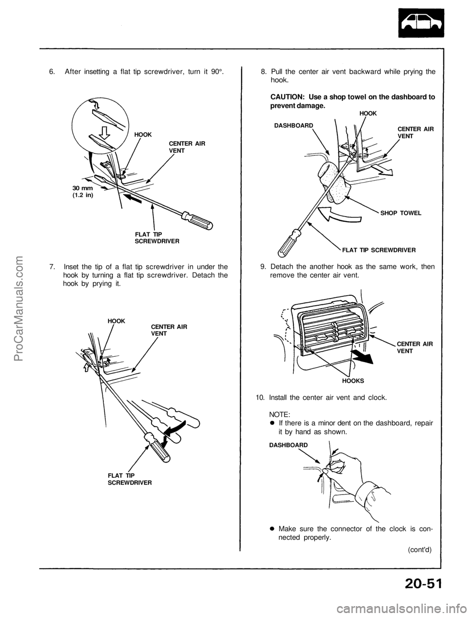
6. After insetting a flat tip screwdriver, turn it 90°.
HOOK
CENTER AIR
VENT
30 mm
(1.2
in)
FLAT TIP
SCREWDRIVER
7. Inset the tip of a flat tip screwdriver in under the
hook by turning a flat tip screwdriver. Detach the
hook by prying it.
HOOK
CENTER AIR
VENT
FLAT TIP
SCREWDRIVER
8. Pull the center air vent backward while prying the
hook.
CAUTION: Use a shop towel on the dashboard to
prevent damage.
DASHBOARD
HOOK
CENTER AIR
VENT
SHOP TOWEL
FLAT TIP SCREWDRIVER
9. Detach the another hook as the same work, then
remove the center air vent.
CENTER AIR
VENT
HOOKS
10. Install the center air vent and clock.
NOTE:
DASHBOARD
Make sure the connector of the clock is con-
nected properly.
(cont'd)
If there is a minor dent on the dashboard, repair
it by hand as shown.ProCarManuals.com
Page 1379 of 1640
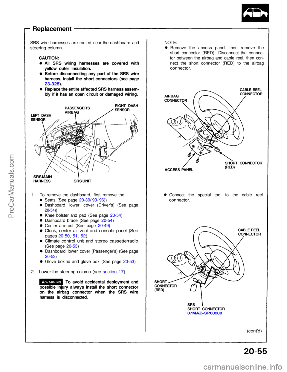
Replacement
SRS wire harnesses are routed near the dashboard and
steering column.
CAUTION:All SRS wiring harnesses are covered with
yellow outer insulation.Before disconnecting any part of the SRS wire
harness, install the short connectors (see page
23-328).
Replace the entire affected SRS harness assem-
bly if it has an open circuit or damaged wiring.
LEFT DASH
SENSOR
PASSENGER'S
AIRBAG
RIGHT DASH
SENSOR
SRS MAIN
HARNESS
SRS UNIT
1. To remove the dashboard, first remove the: Seats (See page 20-39('93-'96))
Dashboard lower cover (Driver's) (See page
20-54))
Knee bolster and pad (See page 20-54)
Dashboard brace (See page 20-54)
Center armrest (See page 20-49)
Clock, center air vent and console panel (See
pages 20-50, 51, 52)
Climate control unit and stereo cassette/radio
(See page 20-53)Dashboard lower cover (Passenger's) (See page
20-53)
Glove box lid and glove box (See page 20-53)
2. Lower the steering column (see section 17).
To avoid accidental deployment and NOTE:
Remove the access panel, then remove the
short connector (RED). Disconnect the connec-
tor between the airbag and cable reel, then con- nect the short connector (RED) to the airbag
connector.
AIRBAG
CONNECTOR
CABLE REEL
CONNECTOR
ACCESS PANEL SHORT CONNECTOR
(RED)
Connect the special tool to the cable reel
connector.
CABLE REEL
CONNECTOR
SHORT
CONNECTOR
(RED)
SRS
SHORT CONNECTOR
07MAZ–SP00200
(cont'd)
possible injury always install the short connector
on the airbag connector when the SRS wire
harness is disconnected.ProCarManuals.com
Page 1393 of 1640
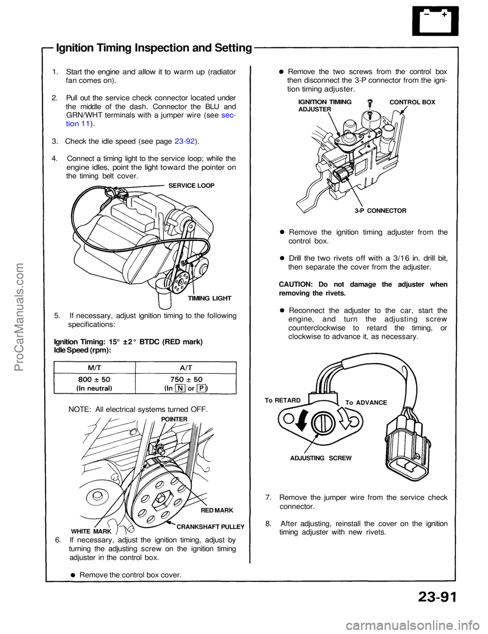
Ignition Timing Inspection and Setting
1. Start the engine and allow it to warm up (radiator
fan comes on).
2. Pull out the service check connector located under the middle of the dash. Connector the BLU andGRN/WHT terminals with a jumper wire (see sec-
tion 11).
3. Check the idle speed (see page 23-92).
4. Connect a timing light to the service loop; while the
engine idles, point the light toward the pointer on
the timing belt cover.
SERVICE LOOP
TIMING LIGHT
5. If necessary, adjust ignition timing to the following specifications:
Ignition Timing: 15° ±2° BTDC (RED mark)
Idle Speed (rpm):
NOTE: All electrical systems turned OFF. POINTER
RED MARK
CRANKSHAFT PULLEY
WHITE MARK
6. If necessary, adjust the ignition timing, adjust by turning the adjusting screw on the ignition timingadjuster in the control box.
Remove the control box cover. 7. Remove the jumper wire from the service check
connector.
8. After adjusting, reinstall the cover on the ignition timing adjuster with new rivets.ADJUSTING SCREW
To ADVANCE
To RETARD Reconnect the adjuster to the car, start the
engine, and turn the adjusting screw
counterclockwise to retard the timing, or
clockwise to advance it, as necessary.
CAUTION: Do not damage the adjuster when
removing the rivets. Remove the ignition timing adjuster from the
control box.
Drill the two rivets off with a 3/16 in. drill bit,
then separate the cover from the adjuster. 3-P CONNECTORCONTROL BOX
IGNITION TIMING
ADJUSTER
Remove the two screws from the control box
then disconnect the 3-P connector from the igni-
tion timing adjuster.ProCarManuals.com