Page 1498 of 1640

Idle Control System
Idle Speed Setting
Inspection/Adjustment
1. Start the engine and warm it up to normal operating temperature (the cooling fan comes on).
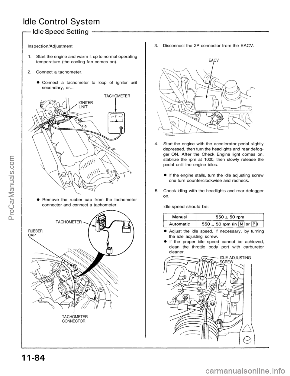
2. Connect a tachometer. Connect a tachometer to loop of igniter unit
secondary, or... 3. Disconnect the 2P connector from the EACV.
EACV
TACHOMETER
IGNITER
UNIT
4. Start the engine with the accelerator pedal slightlydepressed, then turn the headlights and rear defog-
ger ON. After the Check Engine light comes on,stabilize the rpm at 1000, then slowly release the
pedal until the engine idles. If the engine stalls, turn the idle adjusting screw
one turn counterclockwise and recheck.
5. Check idling with the headlights and rear defogger
on.
Idle speed should be:
Remove the rubber cap from the tachometer
connector and connect a tachometer.
TACHOMETER
RUBBER
CAP
Adjust the idle speed, if necessary, by turning
the idle adjusting screw. If the proper idle speed cannot be achieved,
clean the throttle body port with carburetor
cleaner.
IDLE ADJUSTING
SCREW
TACHOMETER CONNECTORProCarManuals.com
Page 1499 of 1640
6. Turn the ignition switch OFF.
7. Reconnect the 2P connector on the EACV, then
remove CLOCK fuse in the under-hood fuse/relay
box for 10 seconds to reset ECU.
8. Restart and idle the engine with no-load conditions
in which the headlights, blower fan, rear defogger,
cooling fan, and air conditioner are not operating
for one minute, then check the idle speed.
Idle speed should be:ProCarManuals.com
Page 1580 of 1640

Dashboard/Center Armrest
Component Removal/Installation
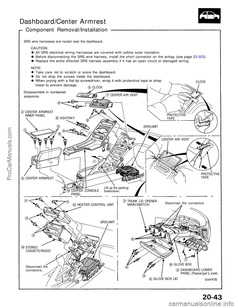
SRS wire harnesses are routed near the dashboard.
CAUTION:
All SRS electrical wiring harnesses are covered with yellow outer insulation.Before disconnecting the SRS wire harness, install the short connector on the airbag (see page 23-323). Replace the entire effected SRS harness assembly if it has an open circuit or damaged wiring.
NOTE: Take care not to scratch or score the dashboard.Do not drop the screws inside the dashboard.
When prying with a flat tip screwdriver, wrap it with protective tape or shop
towel to prevent damage.
Disassemble in numbered
sequence.
CLOCK
CLOCK
CENTER AIR VENT
CENTER ARMREST
INNER PANEL
ASHTRAY
SRS UNIT
CENTER ARMREST CENTER CONSOLE
PANEL
Lift up the parking
brake lever.
HEATER CONTROL UNIT
SRS UNIT
STEREO
CASSETE/RADIO
Disconnect the
connectors.
GLOVE BOX LID
(cont'd)
DASHBOARD LOWER
PANEL (Passenger's side)
GLOVE BOX
Disconnect the connectors
TRUNK LID OPENER
MAIN SWITCH
PROTECTIVE
TAPE
CENTER AIR VENT
PROTECTIVE
TAPEProCarManuals.com
Page 1582 of 1640

Replacement
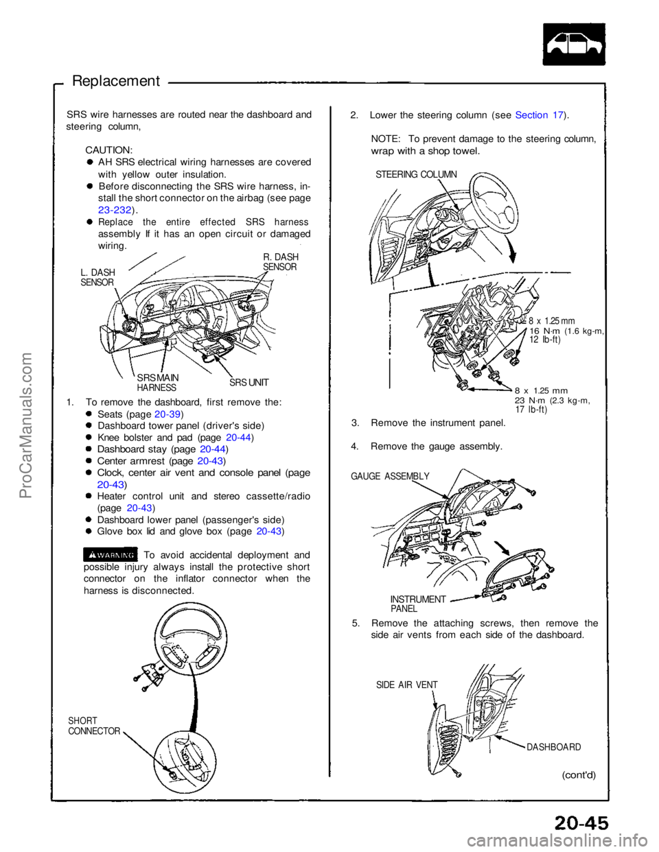
SRS wire harnesses are routed near the dashboard and
steering column,
CAUTION:
AH SRS electrical wiring harnesses are covered
with yellow outer insulation.
Before disconnecting the SRS wire harness, in-
stall the short connector on the airbag (see page
23-232).
Replace the entire effected SRS harness
assembly If it has an open circuit or damaged
wiring.
R. DASH
SENSOR
L. DASH
SENSOR
SRS MAIN
HARNESS
SRS
UNIT
1. To remove the dashboard, first remove the: Seats (page 20-39)
Dashboard tower panel (driver's side)
Knee bolster and pad (page 20-44)
Dashboard stay (page 20-44)
Center armrest (page 20-43)
Clock, center air vent and console panel (page
20-43)
Heater control unit and stereo cassette/radio
(page 20-43)
Dashboard lower panel (passenger's side)
Glove box lid and glove box (page 20-43)
To avoid accidental deployment and
possible injury always install the protective short
connector on the inflator connector when the
harness is disconnected.
SHORT
CONNECTOR
(cont'd)
DASHBOARD
SIDE AIR VENT
5. Remove the attaching screws, then remove the
side air vents from each side of the dashboard.
INSTRUMENT
PANEL
GAUGE ASSEMBLY
3. Remove the instrument panel.
4. Remove the gauge assembly.
8 x
1.25
mm
23 N·m
(2.3 kg-m,
17 lb-ft)
8 x 1.25 mm
16 N·m
(1.6 kg-m,
12 Ib-ft)
STEERING COLUMN
2. Lower the steering column (see Section 17).
NOTE: To prevent damage to the steering column,
wrap with a shop towel.ProCarManuals.com