Page 537 of 1640

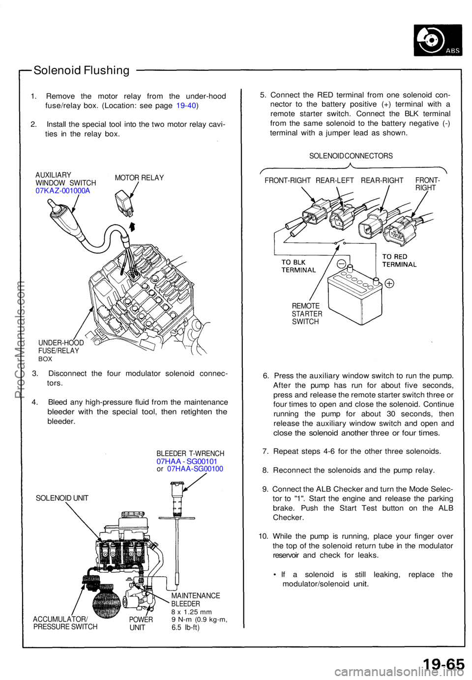
Solenoid Flushin g
1. Remov e th e moto r rela y fro m th e under-hoo d
fuse/rela y box . (Location : se e pag e 19-40 )
2 . Instal l th e specia l too l int o th e tw o moto r rela y cavi -
tie s i n th e rela y box .
AUXILIAR Y
WINDO W SWITC H
07KAZ-001000 A
MOTOR RELA Y
UNDER-HOO DFUSE/RELAYBOX
3. Disconnec t th e fou r modulato r solenoi d connec -
tors .
4 . Blee d an y high-pressur e flui d fro m th e maintenanc e
bleeder wit h th e specia l tool , the n retighte n th e
bleeder .
SOLENOI D UNI T
BLEEDE R T-WRENC H07HAA - SG0010 1or 07HA A-SG0010 0
ACCUMULATOR /
PRESSUR E SWITC HPOWERUNIT
MAINTENANC EBLEEDER8 x 1.2 5 mm9 N- m (0. 9 kg-m ,6.5 Ib-ft )
5. Connec t th e RE D termina l fro m on e solenoi d con -
necto r t o th e batter y positiv e (+ ) termina l wit h a
remot e starte r switch . Connec t th e BL K termina l
fro m th e sam e solenoi d t o th e batter y negativ e (- )
termina l wit h a jumpe r lea d a s shown .
SOLENOI D CONNECTOR S
FRONT-RIGH T REAR-LEF T REAR-RIGH T
FRONT-RIGHT
REMOT ESTARTE RSWITCH
6. Pres s th e auxiliar y windo w switc h t o ru n th e pump .
Afte r th e pum p ha s ru n fo r abou t fiv e seconds ,
pres s an d releas e th e remot e starte r switc h thre e o r
fou r time s t o ope n an d clos e th e solenoid . Continu e
runnin g th e pum p fo r abou t 3 0 seconds , the n
releas e th e auxiliar y windo w switc h an d ope n an d
clos e th e solenoi d anothe r thre e o r fou r times .
7. Repea t step s 4- 6 fo r th e othe r thre e solenoids .
8 . Reconnec t th e solenoid s an d th e pum p relay .
9 . Connec t th e AL B Checke r an d tur n th e Mod e Selec -
to r t o "1" . Star t th e engin e an d releas e th e parkin g
brake . Pus h th e Star t Tes t butto n o n th e AL B
Checker .
10. Whil e th e pum p i s running , plac e you r finge r ove r
th e to p o f th e solenoi d retur n tub e in th e modulato r
reservoi r an d chec k fo r leaks .
• I f a solenoi d i s stil l leaking , replac e th e
modulator/solenoi d
unit.
ProCarManuals.com
Page 595 of 1640

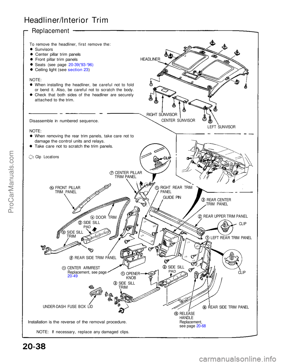
Headliner/lnterior Trim
Replacement
To remove the headliner, first remove the: Sunvisors
Center pillar trim panels
Front pillar trim panels
Seats (see page 20-39('93-'96)
Ceiling light (see section 23)
NOTE:
When installing the headliner, be careful not to fold
or bend it. Also, be careful not to scratch the body.
Check that both sides of the headliner are securely
attached to the trim.
Disassemble in numbered sequence.
NOTE: When removing the rear trim panels, take care not to
damage the control units and relays.
Take care not to scratch the trim panels.
Clip Locations
CENTER PILLAR
TRIM PANEL
FRONT PILLAR
TRIM PANEL
DOOR TRIM
SIDE SILL
PAD
SIDE SILL
TRIM
REAR SIDE TRIM PANEL
CENTER ARMREST
Replacement, see page
20-49
OPENER
KNOB
SIDE SILL
TRIM
UNDER-DASH FUSE BOX LID
Installation is the reverse of the removal procedure.
NOTE: If necessary, replace any damaged clips.
RELEASE
HANDLE
Replacement,
see page 20-68
REAR SIDE TRIM PANEL CLIP
SIDE SILL
PAD
LEFT REAR TRIM PANEL
CLIP
REAR UPPER TRIM PANEL REAR CENTER
TRIM PANEL
GUIDE PIN
RIGHT REAR TRIM
PANEL LEFT SUNVISOR
CENTER SUNVISOR
RIGHT SUNVISOR
HEADLINERProCarManuals.com
Page 604 of 1640
Carpet
Replacement
SRS components are located in this area. Review the SRS component locations, precautions, and procedures in the SRS
section (24) before performing repairs or service.
DASHBOARD
INSIDE SCREW
CARPET
HOOK
(3)
AIR VENT
AM VENT
AIR DUCT
CUPS
FLOOR
CARPET
CONSOLE
CARPET
CONSOLE CARPET
SRS UNIT
SCREW
(cont'd)
1. Remove:
Seats (see page 20-39('93-'96), 38('91-'92)
Footrest
Under-dash fuse box lid (see page 20-38('93-'96),37('91-'92)
Side sill trim (see page 20-38 ('93-'96), 37('91-'92)
Side sill pad (see page 20-38('93-'96), 37('91-'92)
Rear side trim panel (see page 20-38('93-'96), 37('91-'92)
Center armrest (see page 20-49('94-'96)('91-'93)
Center console panel (see page 20-52('94-'96)('91-'93)
2. Detach the clips at The front edge (passenger's).
3. Remove the console carpet attaching screw from the heater unit (passenger's).
4. Disconnect the air duct (driver's) and air vent, then remove the carpet hooks from the dashboard inside screws.ProCarManuals.com
Page 684 of 1640
SRS components are located in this area. Review the SRS component locations, precautions, and procedures in the SRS
section 24 before performing repairs or service.
POWER TRANSISTORBLOWER MOTOR
RECIRCULATION
CONTROL
MOTOR
CONDENSER
FAN MOTOR UNDER-HOOD RELAY BOX A
(CONDENSER FAN RELAY, COMPRESSOR CLUTCH RELAY,
BLOWER MOTOR HIGH RELAY, BLOWER MOTOR RELAY)
UNDER-HOOD
FUSE/RELAY
BOX
HEATER CORE TEMPERATURE SENSOR
CLIMATE CONTROL UNIT VENT DOOR
CONTROL MOTOR
OUTSIDE AIR
TEMPERATURE SENSOR ENGINE COMPARTMENT
FUSE/RELAY BOX
A/C TRIPLE PRESSURE SWITCH
FAN CONTROL UNIT (Fan radiator and con-
denser fans inside car,
behind seats)
EVAPORATOR
TEMPERATURE
SENSOR
IN-CAR
TEMPERATURE
SENSOR
MODE CONTROL
MOTOR
AIR MIX CONTROL MOTOR
SUNLIGHT
SENSORProCarManuals.com
Page 732 of 1640
Relay and Control Unit Locations
Front Compartment
HORN RELAY
A/C COMPRESSOR CLUTCH
RELAY
RADIATOR FAN
LOW RELAY
RADIATOR FAN
HIGH RELAY
CONDENSER FAN RELAY
UNDER-HOOD RELAY BOX A
LEFT HEADLIGHT RETRACTOR
CUT RELAY
WINDSHIELD WIPER
LOW RELAY
WINDSHIELD WIPER
INTERMITTENT RELAY
POWER AMPLIFIER
RELAY
ABS
REAR FAIL-SAFE RELAY
ABS FRONT
FAIL-SAFE RELAY
HEADLIGHT RELAY
RIGHT HEADLIGHT RETRACTOR RELAY
Wire colors: BLU/GRN,
BRN/WHT, BLU/RED,
GRN/YEL, and BLK
LEFT HEADLIGHT RETRACTOR RELAY
Wire colors: BLU/BLK,
WHT/BLK, GRN/RED,
BLU,
and BLK
RIGHT HEADLIGHT RETRACTOR
CUT RELAY
BLOWER RELAY
BLOWER HIGH RELAY
WINDSHIELD WIPER
HIGH RELAY
WINDSHIELD
WASHER RELAY
UNDER-HOOD
RELAY BOX B
DIMMER RELAY
POWER WINDOW
RELAY
TAILLIGHT RELAY
ABS MOTOR RELAY
UNDER-HOOD FUSE/RELAY BOXProCarManuals.com
Page 733 of 1640
Relay and Control Unit Locations
Dashboard
TURN SIGNAL/HAZARD
RELAY
CLIMATE CONTROL UNIT
UNDER-DASH FUSE BOX
FOOT WELL LIGHT
DASHBOARD
LOWER COVER
INTEGRATED
CONTROL UNIT
SRS UNITProCarManuals.com
Page 737 of 1640
Relay and Control Unit Locations
Engine Compartment
REAR WINDOW DEFOGGER
RELAY
ENGINE COMPARTMENT
FAN RELAY (A/T)
Wire colors: YEL/BLK,
BLU/RED, WHT/GRN,
and WHT/BLU
SPARK PLUG VOLTAGE
DETECTION MODULE
ENGINE COMPARTMENT
FUSE/RELAY BOX
IGNITION CONTROL
MODULE (ICM)ProCarManuals.com
Page 741 of 1640
Under-dash Fus e Bo x
Removal/Installatio n
SRS component s ar e locate d in thi s area . Revie w th e SR S
componen t locations , precautions , an d procedure s in th e
SR S sectio n 24 befor e performin g repair s o r service .
Removal :
1. Disconnec t bot h th e negativ e cabl e an d positiv e
cabl e fro m th e battery .
2 . Carefull y remov e th e sid e sil l pa d (pul l i t up , rea r
en d first) .
3 . Remov e th e fus e bo x door .
FUSE BO XDOO R
SIDE SIL L PA D
SIDE SIL L TRI M
4. Remov e th e thre e screws , the n remov e th e sid e sil l
trim .
5. Remov e th e under-das h fus e bo x mountin g bolts . 6
. Disconnec t th e under-das h fus e bo x connectors .
NOTE : Th e SR S mai n harnes s connecto r i s doubl e
locked . T o remov e it , firs t lif t th e connecto r lid ,
the n pres s th e connecto r ta b dow n an d pul l th e
connecto r out .
TAB
SR S MAI N HARNES S
7. Tak e ou t th e under-das h fus e box .
ProCarManuals.com