Page 857 of 1640
Back-up Lights
Component Location Index
A/T GEAR POSITION SWITCH
(Back-u
p
light switch)
Test, page 23-160 ('93-'96) ('91-'92).
UNDER-DASH
FUSE BOX BACK-UP LIGHT SWITCH (M/T)
Test, page 23-208 ('93-'96) ('91-'92).
BACK-UP LIGHTS
Bulb replacement, page 23-206ProCarManuals.com
Page 862 of 1640
Side Marker/Turn Signal/Hazard Flasher System
Component Location Index
SRS components are located in this area. Review the SRS component locations, precautions, and procedures in the SRS
section (24) before performing repairs or service.
TURN SIGNAL INDICATOR LIGHTS(In the gauge assembly)
Gauge Assembly, page 23-125 HAZARD WARNING SWITCH
Removal, page 23-220
Test, page 23-221
HEADLIGHT SWITCH
Test, page 23-181
Replacement, page 23-182
TURN SIGNAL/HAZARD RELAY
Input Test, page 23-218
UNDER-DASH FUSE BOX TURN SIGNAL SWITCH
Test, page 23-181
Replacement, page 23-182 TURN SIGNAL CANCEL UNIT
Input Test, page 23-219
SIDE MARKER FLASHER CIRCUIT
(In the integrated control unit)
Input Test, page 23-168 ('94-'96) ('91-'93)ProCarManuals.com
Page 874 of 1640
Entry Light Timer System
Component Location Index
SRS components are located in this area. Review the SRS
component locations, precautions, and procedures in the
SRS section (24) before performing repairs or service.
Description: It the driver's door has been opened by the
outer handle, the foot well light and a light at the Ignition
switch go on and stay on for about eight seconds after
the driver's door has been dosed.
IGNITION KEY LIGHT
Replacement, page 23-229
FOOT WELL LIGHT
Replacement, page 23-229
DRIVER'S DOOR SWITCH
(Built into the door lock actuator assembly)
Test, page 23-204
UNDER-DASH FUSE BOX ENTRY LIGHT TIMER CIRCUIT
( Built into the integrated control unit)
Input Test, page 23-161 ('93-'96) ('91-'92)
ProCarManuals.com
Page 888 of 1640
Horns
Component Location Index
SRS components are located in this area. Review the
SRS component locations, precautions, and procedures
in the SRS section (24) before performing repairs or ser-
vice.
HORN RELAY
Test, page 23-249
UNDER-HOOD RELAY
BOX A
CABLE REEL
Test, page 23-250
HORN SWITCH
Test, page 23-249
Overhaul, section 17
SECURITY HORNTest, page 23-248
LEFT HORN
Test, page 23-248
RIGHT HORN
Test, page 23-248
SECURITY CONTROL
UNIT
Inpu
t
Test, page 23-320
('94-'96) ('93) ('91-'92)
UNDER-HOOD
FUSE/RELAY BOX
Description
Security Alarm System:
The security alarm system is an anti-theft alarm system. If someone tries to open the trunk, hood or either door without
the ignition key, or if the roof is not fully latched the security control unit senses a signal from the sensors and activates
relays to flash the headlights and sound the horn for about two minutes.ProCarManuals.com
Page 908 of 1640

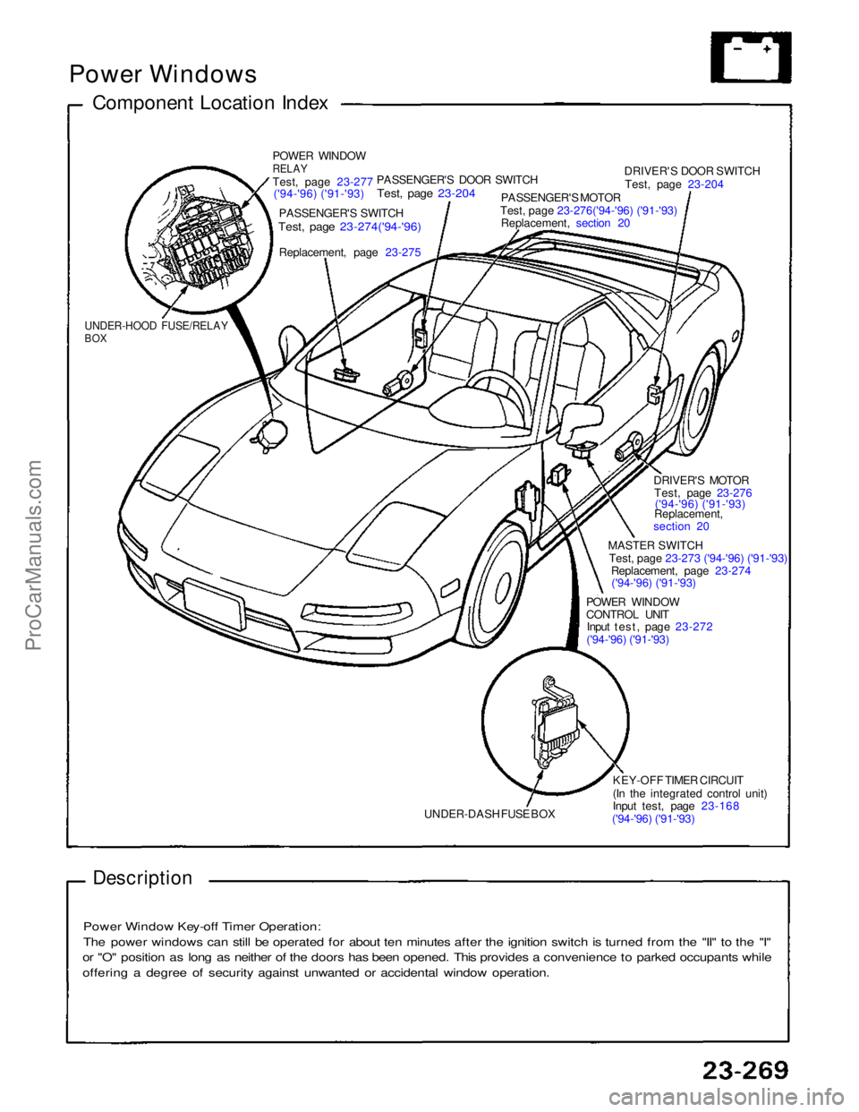
Power Windows
Component Location Index
POWER WINDOW
RELAY
Test
,
page 23-277
('94-'96) ('91-'93)
PASSENGER'S SWITCH
Test, page 23-274('94-'96)
Replacement, page
23-275
PASSENGER'S DOOR SWITCH
Test, page 23-204
PASSENGER'S MOTOR
Test, page 23-276('94-'96) ('91-'93)
Replacement, section 20
DRIVER'S DOOR SWITCH
Test, page 23-204
DRIVER'S MOTORTest, page 23-276('94-'96) ('91-'93)
Replacement,
section 20
MASTER SWITCH
Test, page 23-273 ('94-'96) ('91-'93)
Replacement, page 23-274
('94-'96) ('91-'93)
POWER WINDOW
CONTROL UNIT
Input test, page 23-272
('94-'96) ('91-'93)
KEY-OFF TIMER CIRCUIT
(In the integrated control unit)
Input test, page 23-168
('94-'96) ('91-'93)
UNDER-DASH FUSE BOX
UNDER-HOOD FUSE/RELAY
BOX
Description
Power Window Key-off Timer Operation:
The power windows can still be operated for about ten minutes after the ignition switch is turned from the "II" to the "I"
or "O" position as long as neither of the doors has been opened. This provides a convenience to parked occupants while
offering a degree of security against unwanted or accidental window operation.ProCarManuals.com
Page 916 of 1640
Power Seats
Component Location Index
PASSENGER'S SEAT
DRIVER'S SEAT
RECLINE MOTOR
Test, page 23-273 ('93-'96) ('91-'92) ENGINE COMPARTMENT
FUSE/RELAY BOX
SLIDE MOTOR Test, page 23-281 POWER SEAT SWITCH
Test, page 23-280ProCarManuals.com
Page 945 of 1640

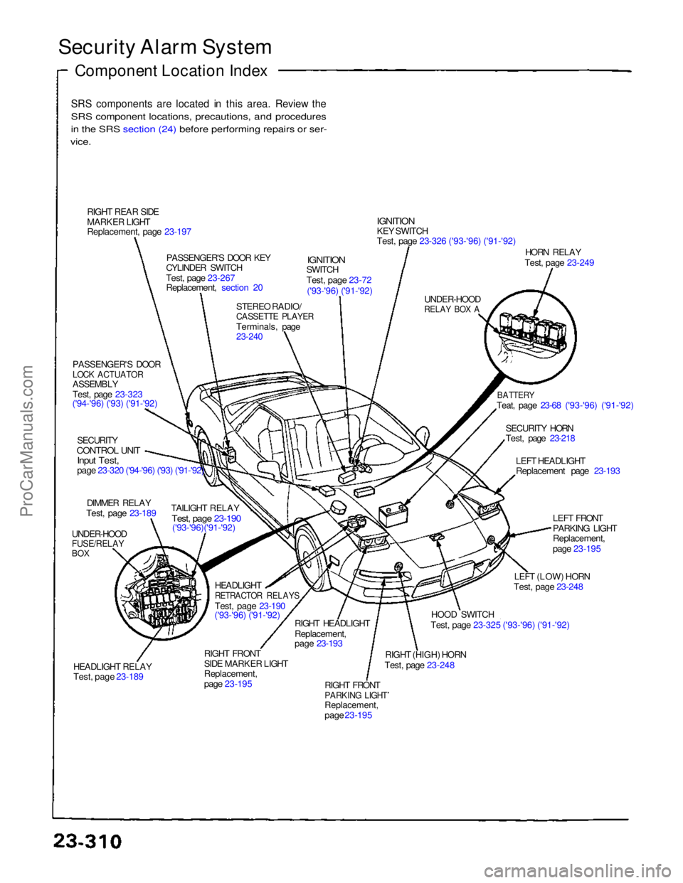
Security Alarm System
Component Location Index
SRS components are located in this area. Review the
SRS component locations, precautions, and procedures
i
n
the SRS section (24) before performing repairs or ser-
vice.
RIGHT REAR SIDE
MARKER LIGHT
Replacement, page 23-197 PASSENGER'S DOOR KEY
CYLINDER SWITCH
Test, page 23-267
Replacement, section 20
STEREO RADIO/
CASSETTE PLAYER
Terminals, page
23-240
IGNITION
SWITCH
Test, page 23-72
('93-'96) ('91-'92)
IGNITION
KEY SWITCH
Test, page 23-326 ('93-'96) ('91-'92)
UNDER-HOOD
RELAY BOX A
HORN RELAY
Test, page 23-249
BATTERY
Teat, page 23-68 ('93-'96) ('91-'92)
SECURITY HORN
Test, page 23-218 LEFT HEADLIGHT
Replacement page 23-193
LEFT FRONT
PARKING LIGHT
Replacement,
page 23-195
LEFT (LOW) HORN
Test, page 23-248
HOOD SWITCH
Test, page 23-325 ('93-'96) ('91-'92)
RIGHT (HIGH) HORN
Test, page 23-248
RIGHT FRONT
PARKING LIGHT
Replacement,
page 23-195
RIGHT HEADLIGHT
Replacement,
page 23-193
RIGHT FRONT
SIDE MARKER LIGHT
Replacement,
page 23-195 HEADLIGHT
RETRACTOR RELAYS
Test, page 23-190
('93-'96) ('91-'92)
HEADLIGHT RELAY
Test, page 23-189 TAILIGHT RELAY
Test, page 23-190
('93-'96)('91-'92)
UNDER-HOOD
FUSE/RELAY
BOX
DIMMER RELAY
Test, page 23-189
SECURITY
CONTROL UNIT
Input Test,
page 23-320 ('94-'96) ('93) ('91-'92)
PASSENGER'S DOOR
LOCK ACTUATOR
ASSEMBLY
Test, page 23-323
('94-'96) ('93) ('91-'92)ProCarManuals.com
Page 1209 of 1640

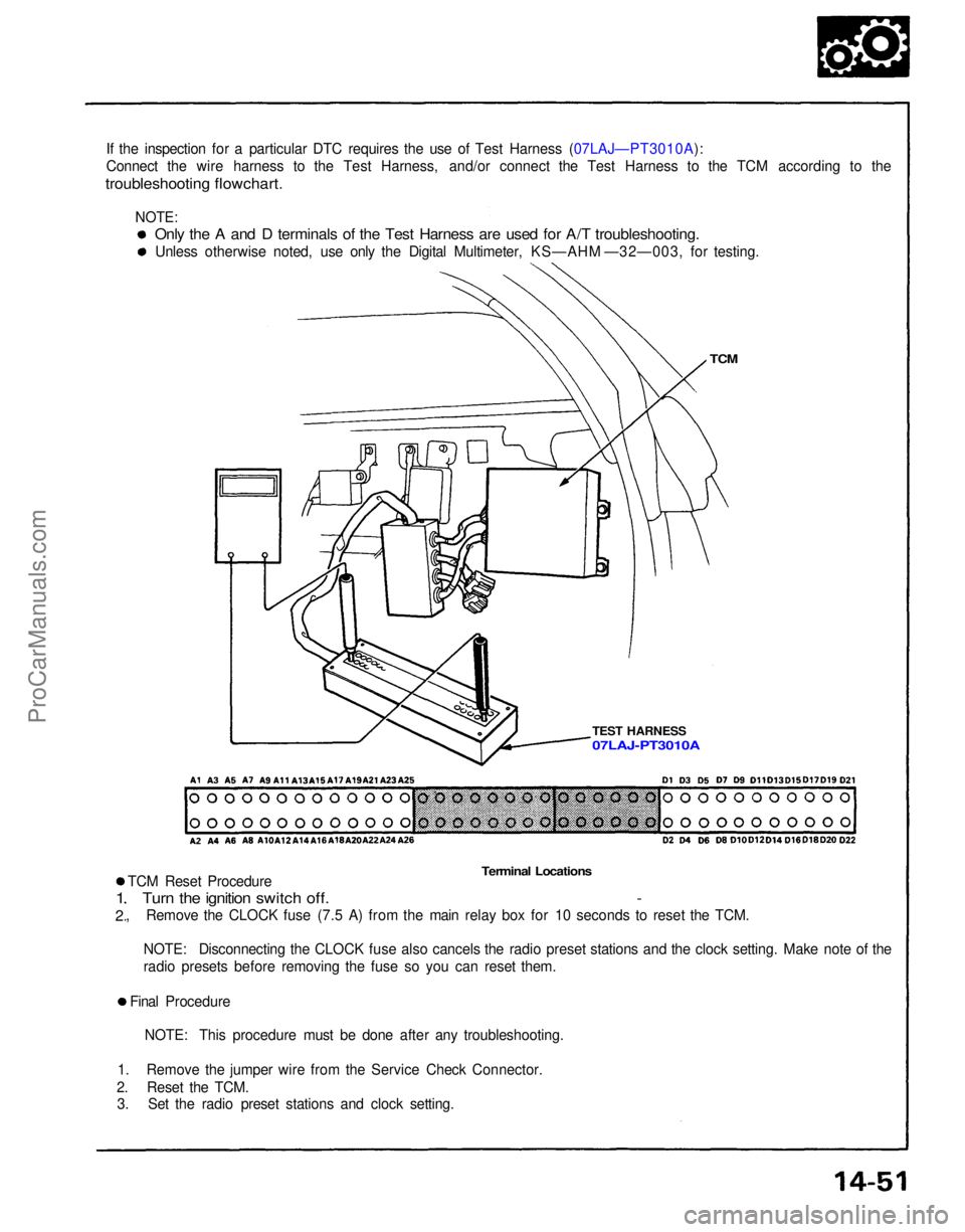
If the inspection for a particular DTC requires the use of Test Harness (07LAJ—PT3010A):
Connect the wire harness to the Test Harness, and/or connect the Test Harness to the TCM according to the
troubleshooting flowchart.
TCM
TEST HARNESS
Terminal Locations
TCM Reset Procedure
Turn the ignition switch off. -
, Remove the CLOCK fuse (7.5 A) from the main relay box for 10 seconds to reset the TCM.
1
2
NOTE: Disconnecting the CLOCK fuse also cancels the radio preset stations and the clock setting. Make note of the
radio presets before removing the fuse so you can reset them.
Final Procedure NOTE: This procedure must be done after any troubleshooting.
1. Remove the jumper wire from the Service Check Connector.
2. Reset the TCM. 3. Set the radio preset stations and clock setting.
Only the A and D terminals of the Test Harness are used for A/T troubleshooting.
Unless otherwise noted, use only the Digital Multimeter, KS—AHM —32—003, for testing.
07LAJ-PT3010A
NOTE:ProCarManuals.com