Page 232 of 2103

ENGINE OVERHAUL
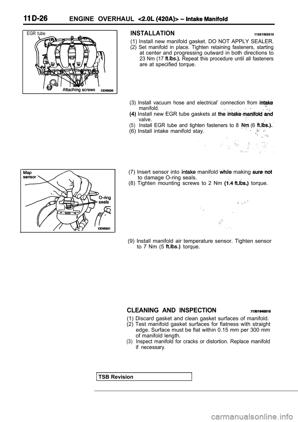
EGR tubeINSTALLATION11661966616
(1) Install new manifold gasket. DO NOT APPLY SEALER.
(2) Set manifold in place. Tighten retaining fasteners, starting
at center and progressing outward in both direction s to
23 Nm (17 Repeat this procedure until all fasteners
are at specified torque.
(3) Install vacuum hose and electrical’ connection from
manifold. .
(4) Install new EGR tube gaskets at
valve.
(5)Install EGR tube and tighten fasteners to 8 (6
(6) Install intake manifold stay. .
(7) Insert sensor into manifold making
to damage O-ring seals.
(8) Tighten mounting screws to 2 Nm torque.
(9) Install manifold air temperature sensor. Tighte
n sensor
to 7 Nm (5
torque.
CLEANING AND INSPECTION
(1) Discard gasket and clean gasket surfaces of man ifold.
(2) Test manifold gasket surfaces for flatness with straight
edge. Surface must be flat within 0.15 mm per 300 m m
of manifold length.
(3)Inspect manifold for cracks or distortion. Replace manifold
if necessary.
TSB Revision
Page 236 of 2103
11 ENGINE OVERHAUL
(9) Install head cover assembly to head and tighten
fasteners in sequence shown in the figure. Using th e
3 step torque method:
Step 1 Tighten all fasteners to 4.5 Nm (3.3
Step 2 Tighten all fasteners to 9.0 Nm (6.5
Step 3 Tighten all fasteners to 12 Nm (9
Spark plug well gaskets
TSB Revision
Page 237 of 2103

(1) Inspect camshaft bearing journals for damage and bind-
ing.
If journals are binding, also check the cylinder head bear-
ing surface for damage, and check the camshaft bearing
oil feed holes in the cylinder head for clogging.
(2) Check the cam surface for abnormal wear and damage.
Replace if defective. Also measure the cam height and
replace if out of limit.
Standard value: 0.0254 mm
in.)
Limit: 0.254 mm in.)
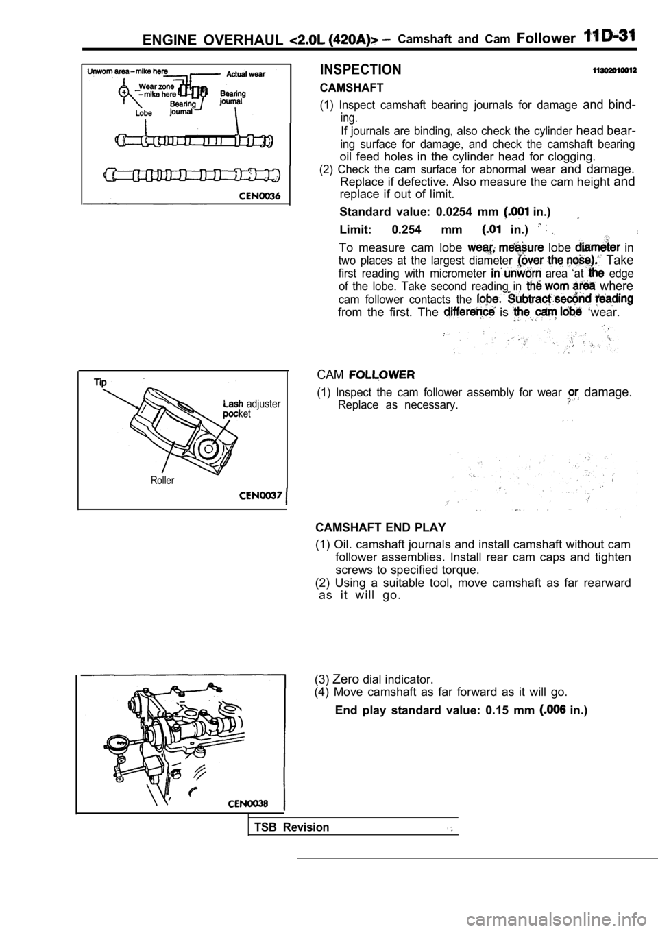
To measure cam lobe lobe in
two places at the largest diameter Take
first reading with micrometer area ‘at edge
of the lobe. Take second reading in
where
cam follower contacts the
from the first. The is ‘wear.
ENGINE OVERHAUL Camshaft and Cam Follower
INSPECTION
CAMSHAFT
adjusterket
Roller
CAM
(1) Inspect the cam follower assembly for wear damage.
Replace as necessary.
CAMSHAFT END PLAY
(1) Oil. camshaft journals and install camshaft wit hout cam
follower assemblies. Install rear cam caps and tigh ten
screws to specified torque.
(2) Using a suitable tool, move camshaft as far rea rward
a s i t w i l l g o .
(3) Zero dial indicator.
(4) Move camshaft as far forward as it will go.
End play standard value: 0.15 mm
in.)
TSB Revision
Page 240 of 2103
11ENGINE OVERHAUL Cylinder
l
(6) Tighten the cylinder head bolts in the sequence shown
in the figure.
Using the 4 step torque turn method, tighten accord ing
to the following values:
Step
Tighten center fasteners 1 thru 6 to 33 Nm (24
then outer fasteners 7 thru 10 to 26
(20
2
Tighten center fasteners
to 67. Nm (46
then outer fasteners’ 7 to 28 Nm
(20,
Step 3 Tighten center fasteners 1
6 to (46
then outer fasteners 7 thru to
(20
Step 4
Turn all fasteners 1 thru 10 turn (90 degrees).
Do not use a torque wrench for step.
Revision
Page 241 of 2103

E N G I N E O V E R H A U L Cylinder
INSPECTION11390790119
Middle
Cut away view
of valve guide
measurement
locations
Bottom
Tester valve
sprin
CYLINDER HEAD
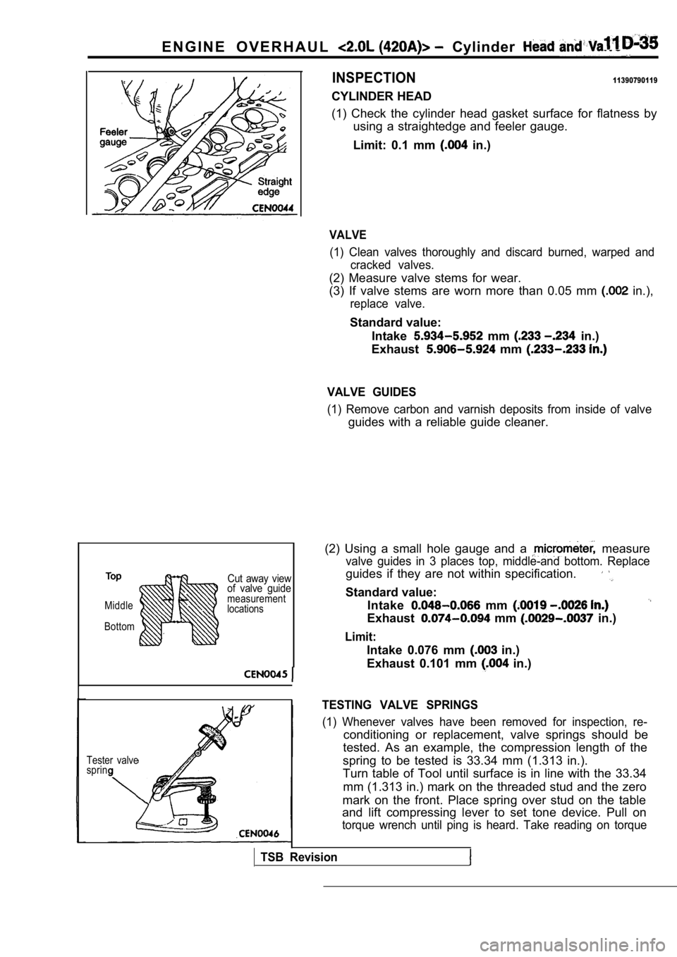
(1) Check the cylinder head gasket surface for flat ness by
using a straightedge and feeler gauge.
Limit: 0.1 mm
in.)
VALVE
(1) Clean valves thoroughly and discard burned, war ped and
cracked valves.
(2) Measure valve stems for wear.
(3) If valve stems are worn more than 0.05 mm
in.),
replace valve.
Standard value:
Intake
mm in.)
Exhaust
mm
VALVE GUIDES
(1) Remove carbon and varnish deposits from inside of valve
guides with a reliable guide cleaner.
(2) Using a small hole gauge and a
measure
valve guides in 3 places top, middle-and bottom. Re place
guides if they are not within specification.
Standard value:
Intake
mm
Exhaust mm in.)
Limit:
Intake 0.076 mm in.)
Exhaust 0.101 mm
in.)
TESTING VALVE SPRINGS
(1) Whenever valves have been removed for inspectio n, re-
conditioning or replacement, valve springs should be
tested. As an example, the compression length of th e
spring to be tested is 33.34 mm (1.313 in.).
Turn table of Tool until surface is in line with th e 33.34
mm (1.313 in.) mark on the threaded stud and the ze ro
mark on the front. Place spring over stud on the ta ble
and lift compressing lever to set tone device. Pull on
torque wrench until ping is heard. Take reading on torque
TSB Revision
Page 247 of 2103
E N G I N E O V E R H A U L Oil ‘Pan and Oil Pump
Locating
I
adapter
Locate wrench
at base of filter
(7)Apply Loctite 18716 or equivalent at the to
bed plate parting line.
(8) Install the oil pan gasket to the plate. Mopar
Silicone Rubber Adhesive Sealant or equivalent to h old
in place.
(9) Install oil pan and tighten the to 12 Nm (9
(lO)Ensure O-ring is in the groove on adapter. Alig n roll
pin into engine block and tighten assembly to 55 Nm
(40
Caution
When servicing the oil filter avoid deforming the f ilter
can by installing the remove/install tool band strap
against the can-to-base lockseam. The join-
ing the can to the base is reinforced by the base
plate.
new filter gasket and install it on filter.
filter mounting surface. The surface must be
smooth, flat and free of debris or old pieces of rubber.
filter on until gasket contacts base. Tighten to
turn or Torque to 21 Nm (15
rear plate.
flywheel or drive plate.
TSB Revision
Page 257 of 2103
Rod
a n d
(8) Install each bolt finger tight then alternately torque each
nut to. assemble the cap properly.
(9) Tighten the bolts to 27.0 Nm PLUS turn (20
PLUS turn). Do not use a torque wrench for last
step.
Oil seal
95059
seal
8995060
I
(lO)Using a feeler gauge, check connecting rod’ sid e clear-’
Standard value: mm in.)
Limit 0.37 mm
in.)
Caution
If burr’or scratch is present on the edge
(chamfer), cleanup with 400 grit paper to prevent
seal damage during’
new’
NOTE
When installing seal, no lube on seal is needed.
(11) Place Special Tool on crankshaft. This is a
pilot tool with a magnetic base.
seal over pilot tool. Make sure you can read
the words THIS SIDE OUT on seal. Pilot tool should
remain on crankshaft during
of seal.
the seal into the block using Special Tool
and handle until the tool bottoms out against
the block.
Caution
If the seal is driven into the past flush,
may cause an oil leak.
Page 260 of 2103

piston,
ENGINE OVERHAUL Cylinder Block
CONNECTING BEARING
(1) Place a piece of Plastigage across the, width of
bearing in the cap 6.35
mm off center and away -from the hole.
suspect areas can be checked, by placing in
the suspect area.
(2) Before assembling the rod with in place;
‘the crankshaft must be rotated the connecting rod
being checked starts moving toward the top of the e ngine.,
Only then should the cap be and torqued
to the specification.
Do not rotate the crankshaft while assembling the cap
or the Plastigage may be smeared, giving inaccurate re-
sults.
(3) Remove the bearing cap and compare the width of the
flattened Plastigage with the metric scale provided on
the package.
Standard value: mm in.)
Limit: 0.075 mm
in.)
bolt
Threads are not straight on line
Threads are straight
line,
bolt
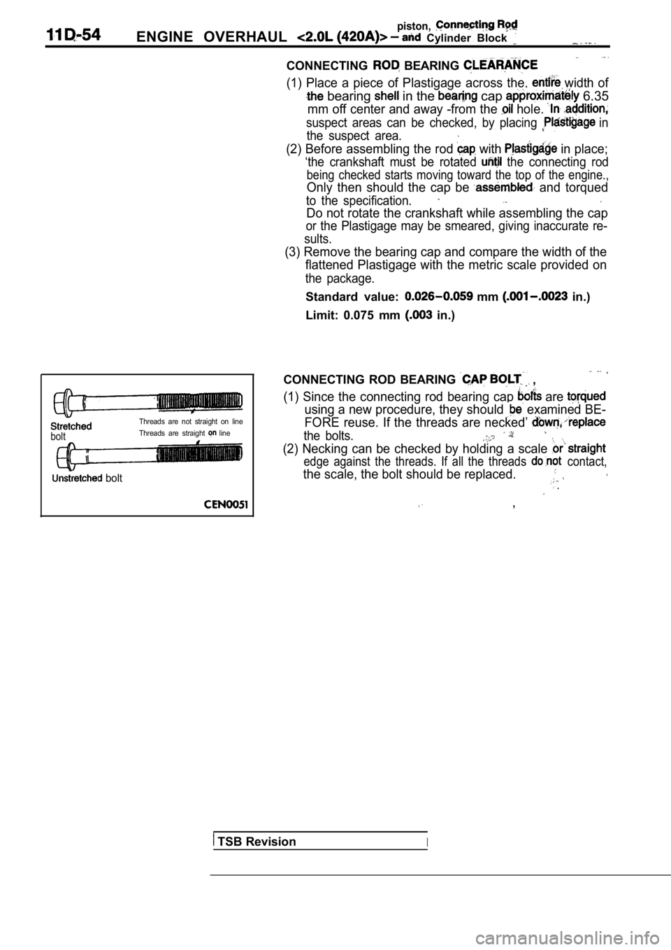
CONNECTING ROD BEARING ,
(1) Since the connecting rod bearing cap are
using a new procedure, they should examined BE-
FORE reuse. If the threads are necked’
the bolts.
(2) Necking can be checked by holding a scale
edge against the threads. If all the threads contact,
the scale, the bolt should be replaced. .
,
TSB RevisionI