Page 577 of 2103
ENGINE
AND ENGINE> Troubleshooting
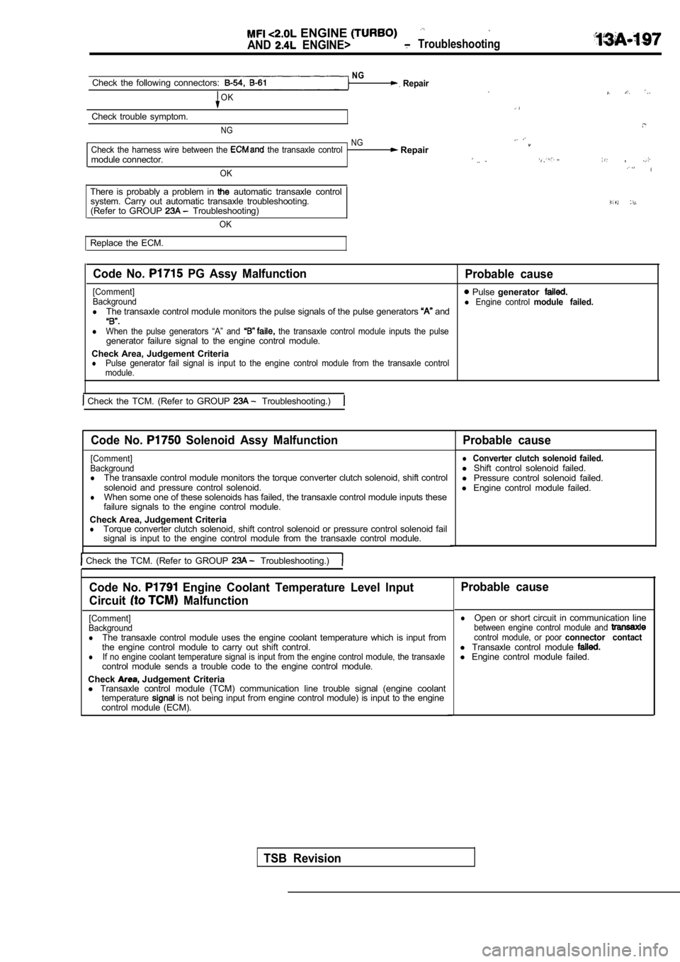
NGCheck the following connectors: Repair
OK
Check trouble symptom.
NG
NGCheck the harness wire between the the transaxle control Repairmodule connector. ,
OK
There is probably a problem in automatic transaxle control
system. Carry out automatic transaxle troubleshooti ng.
(Refer to GROUP Troubleshooting)
OK
Replace the ECM.
Code No. PG Assy Malfunction
Probable cause
[Comment] Pulse generatorBackgroundl Engine control module failed.lThe transaxle control module monitors the pulse sig nals of the pulse generators and
lWhen the pulse generators “A” and the transaxle control module inputs the pulsegenerator failure signal to the engine control modu le.
Check Area, Judgement Criteria
lPulse generator fail signal is input to the engine control module from the transaxle control
module.
Check the TCM. (Refer to GROUP Troubleshooting.)
Code No. Solenoid Assy Malfunction Probable cause
[Comment]
Background
lThe transaxle control module monitors the torque co nverter clutch solenoid, shift control
solenoid and pressure control solenoid.
lWhen some one of these solenoids has failed, the tr ansaxle control module inputs these
failure signals to the engine control module.
Check Area, Judgement Criteria
lTorque converter clutch solenoid, shift control sol enoid or pressure control solenoid fail
signal is input to the engine control module from t he transaxle control module.
Check the TCM. (Refer to GROUP Troubleshooting.)
l Converter clutch solenoid failed.l Shift control solenoid failed.
l Pressure control solenoid failed.
l Engine control module failed.
Code No. Engine Coolant Temperature Level Input
Circuit
Malfunction
[Comment]
Background
lThe transaxle control module uses the engine coolan t temperature which is input from
the engine control module to carry out shift contro l.
lIf no engine coolant temperature signal is input from the engine control module, the transaxlecontrol module sends a trouble code to the engine c ontrol module.
Check
Judgement Criteria
l Transaxle control module (TCM) communication line t rouble signal (engine coolant
temperature
is not being input from engine control module) is input to the engine
control module (ECM).
Probable cause
lOpen or short circuit in communication linebetween engine control module and control module, or poor connector contactl Transaxle control module l Engine control module failed.
TSB Revision
Page 626 of 2103
E N G I N E
AND ENGINE>
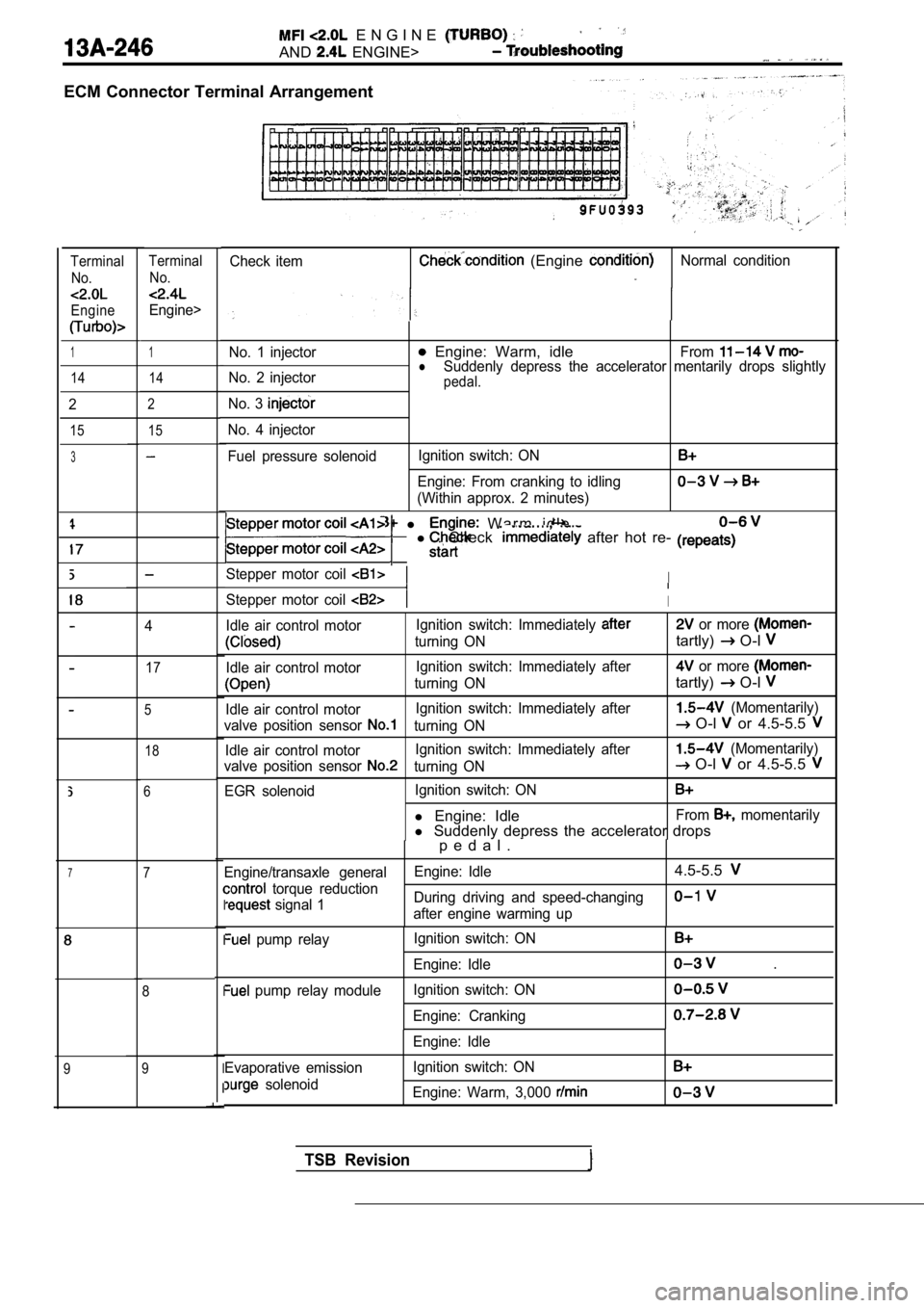
ECM Connector Terminal Arrangement
Check item (Engine Normal conditionTerminalNo.
Engine
TerminalNo.
Engine>
1No. 1 injector Engine: Warm, idleFromlNo. 2 injector Suddenly depress the accelerator mentarily drops sl
ightlypedal.
No. 3
No. 4 injector
Fuel pressure solenoidIgnition switch: ON
Engine: From cranking to idling
(Within approx. 2 minutes)
1
14 14
2
15
2
15
3
l W a r m i d l e
l . Check after hot re-
Stepper motor coil I
Stepper motor coil I
Idle air control motor Ignition switch: Immediately or more
turning ONtartly) O-l
Idle air control motorIgnition switch: Immediately after or more
turning ONtartly) O-l
Idle air control motorIgnition switch: Immediately after (Momentarily)
valve position sensor
turning ON O-l or 4.5-5.5
Idle air control motor Ignition switch: Immediately after (Momentarily)
valve position sensor
turning ON O-l or 4.5-5.5
EGR solenoid Ignition switch: ON
l
Engine: IdleFrom momentarily
l Suddenly depress the accelerator drops
4
17
5
18
6
p e d a l .
Engine/transaxle general Engine: Idle4.5-5.5
torque reduction
signal 1During driving and speed-changingafter engine warming upI
I
I
I
I
pump relay
pump relay module Ignition switch: ON
Engine: Idle
Ignition switch: ON
Engine: Cranking
.
Evaporative emission
solenoid Engine: Idle
Ignition switch: ON
Engine: Warm, 3,000
77
8
9
9
TSB Revision
Page 628 of 2103
ENGINE (TURBO)
AND ENGINE> Troubleshooting
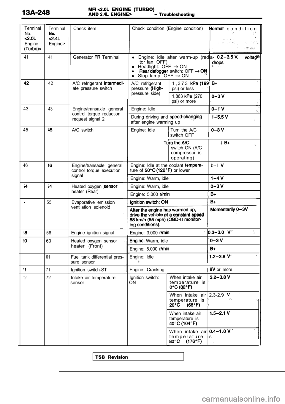
TerminalCheck itemCheck condition (Engine condition) c o n d i t i o n
No.
Engine>
Terminal
No.
Engine
41 41Generator Terminall Engine: idle after warm-up (radia-
tor fan: OFF)
l Headlight: OFF ONl switch: OFF l Stop lamp: OFF ON
A/C refrigerant A/C refrigerant1 , 3 7 3
ate pressure switch
pressurepsi) or less
pressure side)
1,863 (270
psi) or more
Engine/transaxle general
control torque reduction
request signal 2 Engine: Idle
During driving and
after engine warming up
Engine: Idle
Turn the A/C
,
switch OFF
switch ON (A/C
compressor is
operating)
Engine: Idle at the coolant b - l
ture of or lower
Engine: Warm, idle
Engine: Warm, idle
Engine: 5,000
the at a constant speed
Engine: 3,000
Warm, idle
Engine: 5,000
Engine: Idle
I
Engine: CrankingIor more
Ignition switch:
ON When intake air
t e m p e r a t u r e i s
When intake air 2.3-2.9
t e m p e r a t u r e i s
When intake air
temperature is
When intake air
t e m p e r a t u r e i s
.
42
4343
A/C switch45
46Engine/transaxle general
control torque execution
signal
Heated oxygen
heater (Rear)
55Evaporative emission
ventilation solenoid
58Engine ignition signal
Heated oxygen sensor
heater (Front)
60
61Fuel tank differential pres-
sure sensor
71Ignition switch-ST
Intake air temperature
sensor
‘272
TSB Revision
Page 650 of 2103
14. Stop the engine and
Normal if the reading does
it observe
repair according to “the table,
SymptomProbable
Fuel pressure drops gradually afterLeaky injector
engine is stopped inject&. . ,
Leaky fuel regulator valve seat
Fuel pressure drops Check is held. .mediately after engine is stopped open
15. Release residual pressure from the fuel pipe li ne.
(Refer
16. Remove the fuel pressure gauge and special tool from
the fuel rail.
Caution
Cover the hose connection with a shop towel to pre-
vent splash of fuel that could be caused by some residual pressure in the fuel pipe line.
17. Replace the O-ring at the end of the fuel high pressure
hose with a new one.
16. Fit the fuel high pressure the fuel rail and tighten
the bolts specified torque.
T i g h t e n i n g
‘Apply
drive drive the fuel pump.
(2) Check
fuel for leaks, repair as needed.
,
,
.
.
Page 661 of 2103
COOLANT SENSOR
Caution
Be careful not to touch the tool against the
(resin section) when and
1.Remove engine coolant temperature sensor from the in-,
take manifold.
2.With temperature sensing portion of engine tem-
perature sensor immersed in hot water, check resist ance.
,
Temperature
(32)
20 (66)
40 (104)
60 (176)
Resistance
2.1-2.7
3.If the resistance deviates from the standard value greatly,
replace the sensor.
4. Apply sealant threaded-‘portion. ,
Specified sealant:
NUT locking Part No. 4171 or equivalent,
5. Install engine coolant temperature sensor
it to specified torque.
Sensor tightening torque: 30 Nm (22
6. Fasten harness connectors securely.
Page 670 of 2103
( T U R B O )
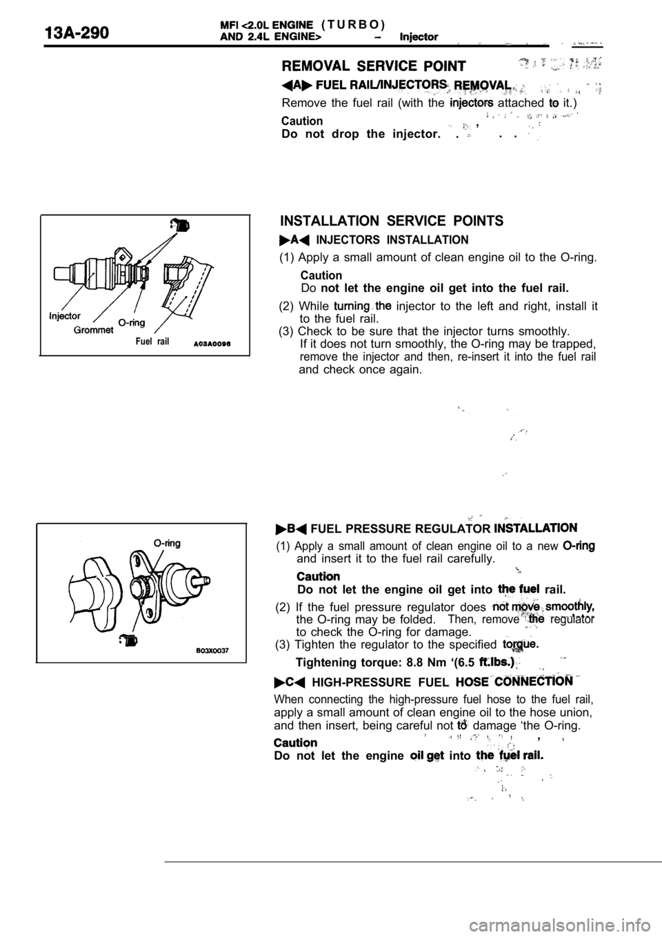
Remove the fuel rail (with the attached it.)
Caution ,
Do not drop the injector.
. . .
Fuel rail
INSTALLATION SERVICE POINTS
INJECTORS INSTALLATION
(1) Apply a small amount of clean engine oil to the O-ring.
Caution
Donot let the engine oil get into the fuel rail.
(2) While
injector to the left and right, install it
to the fuel rail.
(3) Check to be sure that the injector turns smooth ly.
If it does not turn smoothly, the O-ring may be tra pped,
remove the injector and then, re-insert it into the fuel rail
and check once again.
FUEL PRESSURE REGULATOR
(1) Apply a small amount of clean engine oil to a n ew
and insert it to the fuel rail carefully.
Do not let the engine oil get into rail.
(2) If the fuel pressure regulator does
the O-ring may be folded.Then, remove regulator
to check the O-ring for damage.
(3) Tighten the regulator to the specified
Tightening torque: 8.8 Nm ‘(6.5
HIGH-PRESSURE FUEL
When connecting the high-pressure fuel hose to the fuel rail,
apply a small amount of clean engine oil to the hose union,
and then insert, being careful not
damage ‘the O-ring.,
Do not let the engine into
,
Page 687 of 2103
F U E L S U P P L Y Fuel
Fuel gauge unit and
pipe assembly
Mating marks
Fuel gauge unit and
pump assembly
Mating marks
0 0 0 0 5 3 3 0
(7) After applying soapy water
fuel tank. Use the special tool to ,
specified torque so
the fuel
the fuel gauge unit and pump assembly (or
unit and pipe assembly) are aligned.
Caution
Make sure that the fuel gauge unit and
(or the fuel gauge unit and does not
turn together with the cap ‘when
cap.
If the
marks the of
the float will
light and the fuel
Caution
The packing should be as in the
illustration.
(8) Check for leaks from the installation section o f the
gauge unit and pump assembly or the fuel gauge
and pipe assembly by procedure.
1.Apply soapy water to the circumference of the cap.
2. Choke the vapor hose
main apply a n
internal pressure of 10
or less
the return hose and check to be that no bu
f o r m i n t h e s o a p y
TSB Revision
Page 694 of 2103
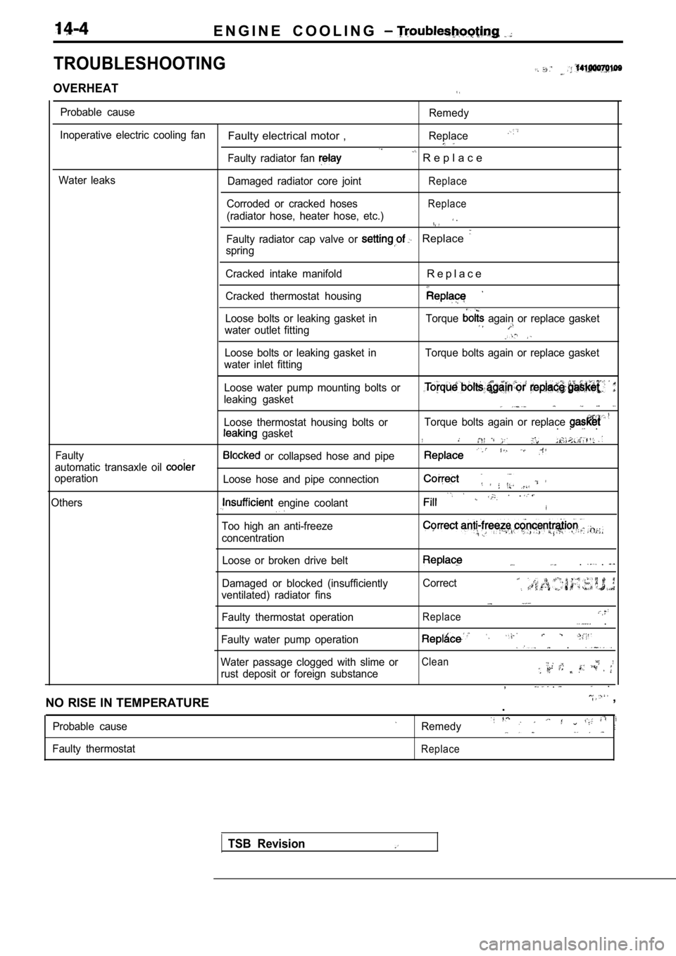
E N G I N E C O O L I N G
TROUBLESHOOTING
OVERHEAT
Probable cause
Inoperative electric cooling fan
Water leaks
Faulty electrical motor ,
Faulty radiator fan
Damaged radiator core joint
Corroded or cracked hoses
(radiator hose, heater hose, etc.)
Remedy
Replace
R e p l a c e
Replace
Replace
.
Faulty radiator cap valve or Replace
spring
Cracked intake manifold
Cracked thermostat housing
R e p l a c e
Loose bolts or leaking gasket in
water outlet fitting Torque again or replace gasket
Loose bolts or leaking gasket in
water inlet fitting Torque bolts again or replace gasket
Faulty Loose water pump mounting bolts or
leaking gasket
Loose thermostat housing bolts or
gasket
automatic transaxle oil
operation
Others
or collapsed hose and pipe
Loose hose and pipe connection
engine coolant
Too high an anti-freeze
concentration
Torque bolts again or replace . . .
.
Loose or broken drive belt
Damaged or blocked (insufficiently
ventilated) radiator fins
Faulty thermostat operation. .
Correct
Replace .
Faulty water pump operation .
Water passage clogged with slime orClean
rust deposit or foreign substance, . .
NO RISE IN TEMPERATURE
,
.
Probable cause
Faulty thermostatRemedy
Replace
TSB Revision