Page 305 of 2103
E N G I N E Timing Belt
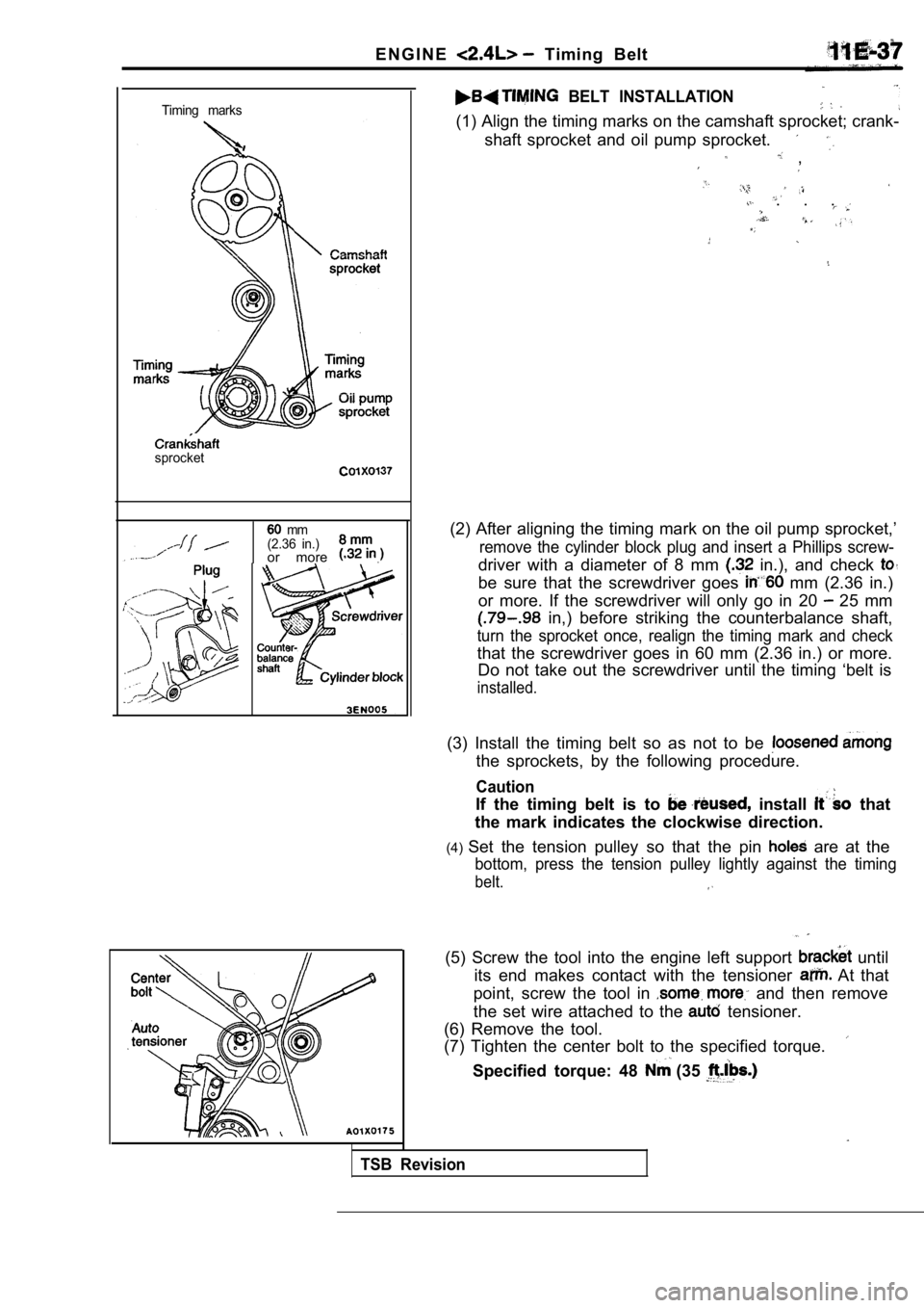
Timing marks
sprocket
mm
(2.36 in.)
or more .
BELT INSTALLATION
(1) Align the timing marks on the camshaft sprocket ; crank-
shaft sprocket and oil pump sprocket.
,
. . .
(2) After aligning the timing mark on the oil pump sprocket,’
remove the cylinder block plug and insert a Phillips screw-
driver with a diameter of 8 mm in.), and check
be sure that the screwdriver goes mm (2.36 in.)
or more. If the screwdriver will only go in 20
25 mm
in,) before striking the counterbalance shaft,
turn the sprocket once, realign the timing mark and check
that the screwdriver goes in 60 mm (2.36 in.) or mo re.
Do not take out the screwdriver until the timing ‘b elt is
installed.
(3) Install the timing belt so as not to be
the sprockets, by the following procedure.
Caution
If the timing belt is to install that
the mark indicates the clockwise direction.
(4) Set the tension pulley so that the pin
are at the
bottom, press the tension pulley lightly against th e timing
belt.
TSB Revision
(5) Screw the tool into the engine left support until
its end makes contact with the tensioner
At that
point, screw the tool in
and then remove
the set wire attached to the
tensioner.
(6) Remove the tool.
(7) Tighten the center bolt to the specified torque .
Specified torque: 48 (35
Page 306 of 2103
ENGINE Belt
48
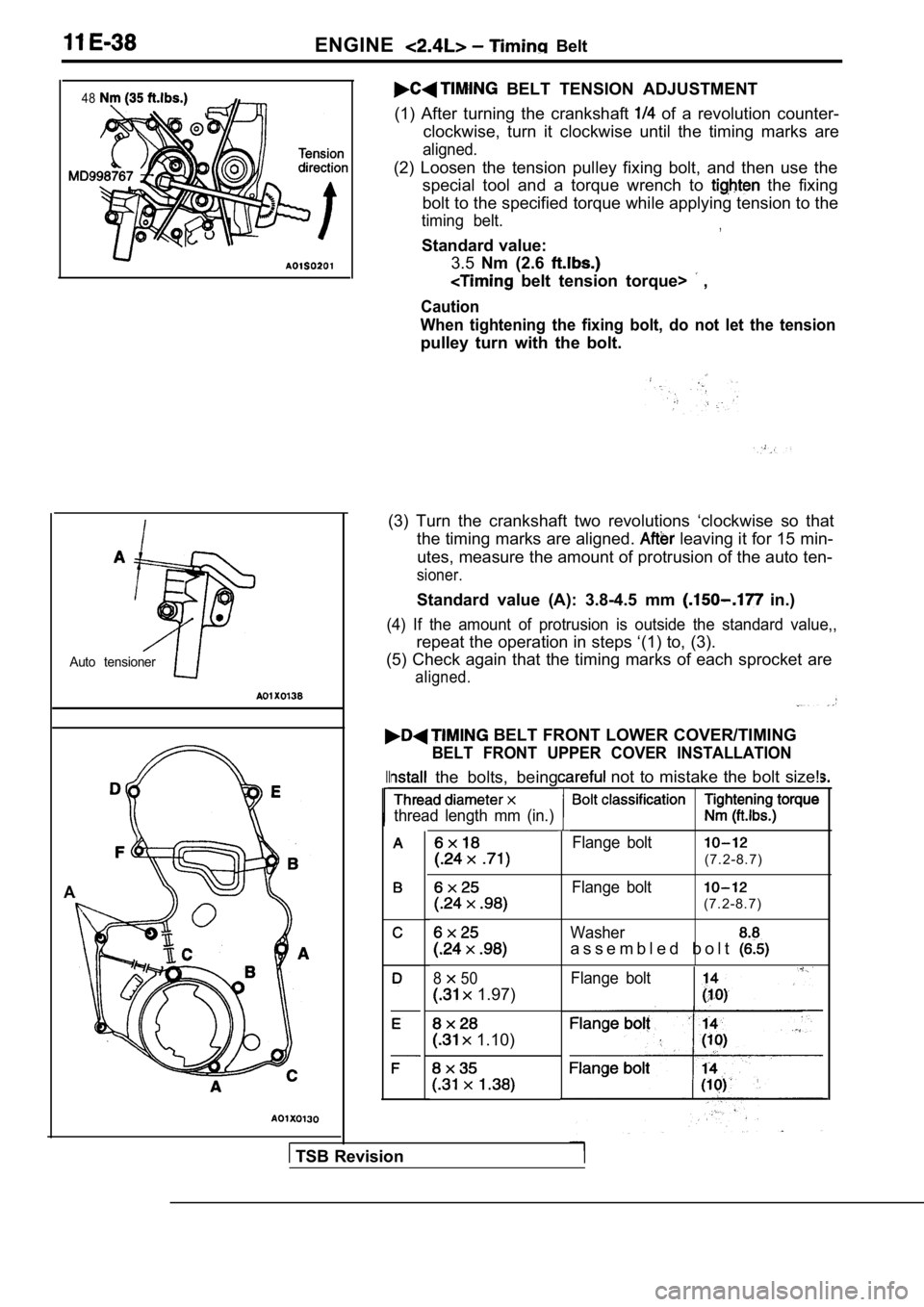
Auto tensioner
A
BELT TENSION ADJUSTMENT
(1) After turning the crankshaft
of a revolution counter-
clockwise, turn it clockwise until the timing marks are
aligned.
(2) Loosen the tension pulley fixing bolt, and then use the
special tool and a torque wrench to
the fixing
bolt to the specified torque while applying tension to the
timing belt.,
Standard value:
3.5 Nm (2.6
belt tension torque> ,
Caution
When tightening the fixing bolt, do not let the ten sion
pulley turn with the bolt.
(3) Turn the crankshaft two revolutions ‘clockwise so that
the timing marks are aligned.
leaving it for 15 min-
utes, measure the amount of protrusion of the auto ten-
sioner.
Standard value (A): 3.8-4.5 mm in.)
(4) If the amount of protrusion is outside the standard value,,
repeat the operation in steps ‘(1) to, (3).
(5) Check again that the timing marks of each sproc ket are
aligned.
BELT FRONT LOWER COVER/TIMING
BELT FRONT UPPER COVER INSTALLATION
II the bolts, being
thread length mm (in.)
850
1.97)
1.10)
not to mistake the bolt size!
Flange bolt
(7.2-8.7)
Flange bolt
(7.2-8.7)
Washer
a s s e m b l e d b o l t
Flange bolt
TSB Revision
Page 314 of 2103
ENGINE OVERHAUL
Crankshaft, flywheel and drive plate,
Cylinder block
REWORK DIMENSIONS
Cylinder head and valve
Crankshaft, flywheel and drive plate
TORQUE SPECIFICATIONS
Generator and ignition system
I‘
TSB Revision
Page 327 of 2103
ENGINE OVERHAUL Timing Belt
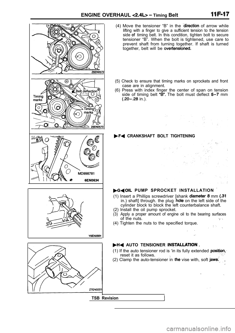
(4) Move the tensioner “B” in the of arrow while
lifting with a finger to give a sufficient tension to the tension
side timing belt. In this condition, tighten bolt to secure
tensioner “B”. When the bolt is tightened, use care to
prevent shaft from turning together. If shaft is tu rned
together, belt will be
(5) Check to ensure that timing marks on sprockets and front
case are in alignment.
(6) Press with index finger the center of span on t ension
side of timing belt
The bolt must deflect mm
in.).
CRANKSHAFT BOLT TIGHTENING
P U M P S P R O C K E T I N S T A L L A T I O N
(1) Insert a Phillips screwdriver [shank mm
in.) shaft] through. the plug on the left side of the
cylinder block to block the left counterbalance sha ft.
(2) Install the oil pump sprocket.
(3) Apply a proper amount of engine oil to the beari ng surfaces
of the nuts.
(4) Tighten the nuts to the specified torque.
AUTO TENSIONER .
(1) If the auto tensioner rod is ‘in its fully exte nded
reset it as follows.
(2) Clamp the auto-tensioner in vise with, soft ,
TSB Revision
Page 328 of 2103
E N G I N E O V E R H A U L Belt
(3) Push in the rod little by little with the until the set
hole A in the rod is the hole in cylinder.
(4) a wire mm’ in.) the set
holes.
Unclamp the auto tensioner vise.
,
(6) Install the auto tensioner to front case tighten to
the specified torque.
Caution,
Leave the wire the
. . .
TENSIONER PULLEY INSTALLATION
Install the tensioner pulley in such that its small
holes are arranged vertically.
TIMING BELT INSTALLATION
(1) Check that the timing belt tensioner and have b een,
installed in position. (See
(2) Align timing mark on camshaft sprocket with tim ing mark
on cylinder head.
(3) Align timing mark on crankshaft sprocket with timing mark
on front case.
TSB Revision
Page 329 of 2103
ENGINE OVERHAUL Belt
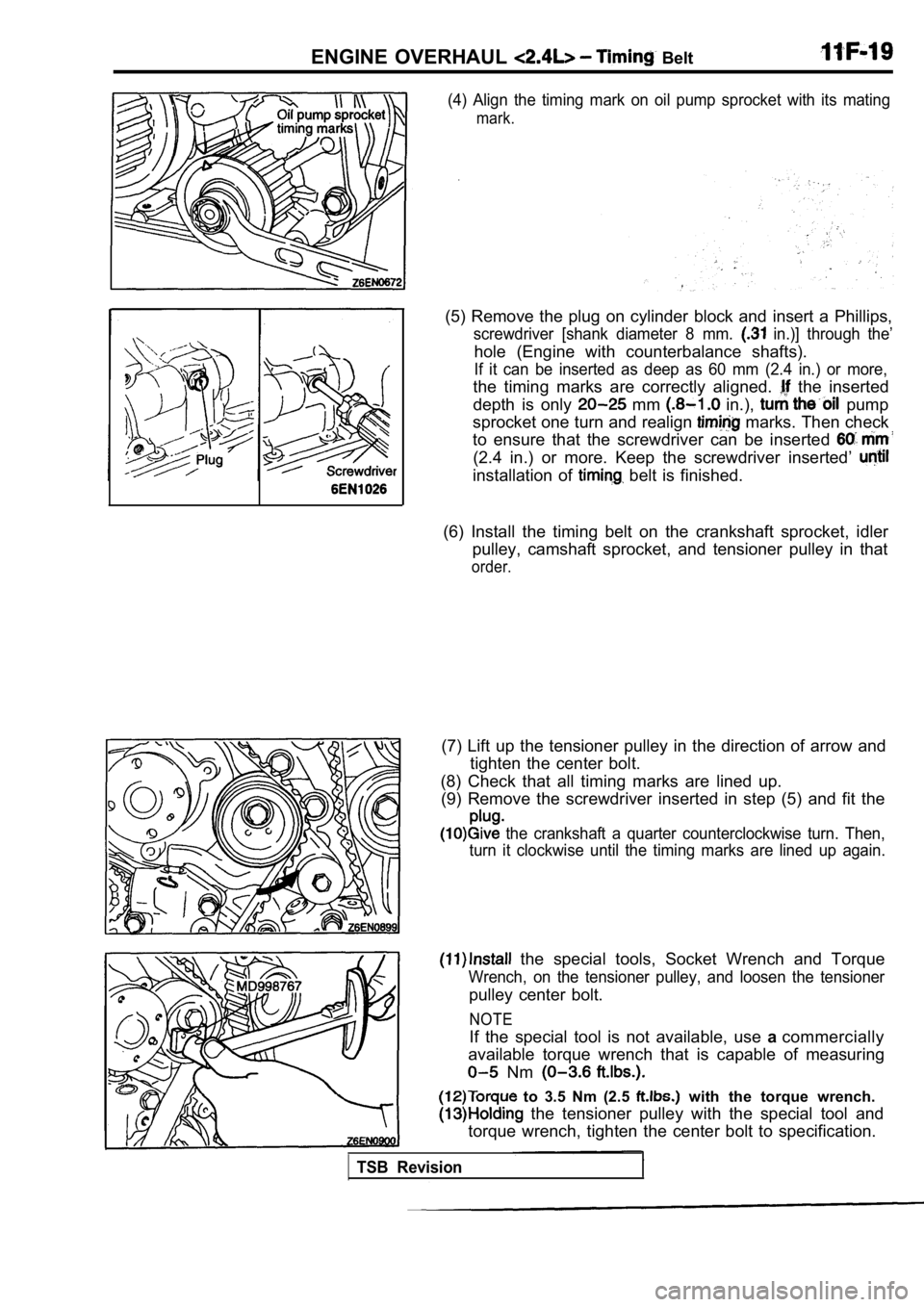
(4) Align the timing mark on oil pump sprocket with its mating
mark.
(5) Remove the plug on cylinder block and insert a Phillips,
screwdriver [shank diameter 8 mm. in.)] through the’
hole (Engine with counterbalance shafts).
If it can be inserted as deep as 60 mm (2.4 in.) or more,
the timing marks are correctly aligned. the inserted
depth is only
mm in.), pump
sprocket one turn and realign
marks. Then check
to ensure that the screwdriver can be inserted
(2.4 in.) or more. Keep the screwdriver inserted’
installation of belt is finished.
(6) Install the timing belt on the crankshaft sproc ket, idler
pulley, camshaft sprocket, and tensioner pulley in that
order.
(7) Lift up the tensioner pulley in the direction of arrow and
tighten the center bolt.
(8) Check that all timing marks are lined up. (9) Remove the screwdriver inserted in step (5) and fit the
the crankshaft a quarter counterclockwise turn. Then,
turn it clockwise until the timing marks are lined up again.
the special tools, Socket Wrench and Torque
Wrench, on the tensioner pulley, and loosen the ten sioner
pulley center bolt.
to 3.5 Nm (2.5 with the torque wrench.
the tensioner pulley with the special tool and
torque wrench, tighten the center bolt to specifica tion.
NOTE
If the special tool is not available, use acommercially
available torque wrench that is capable of measurin g
Nm
TSB Revision
Page 346 of 2103
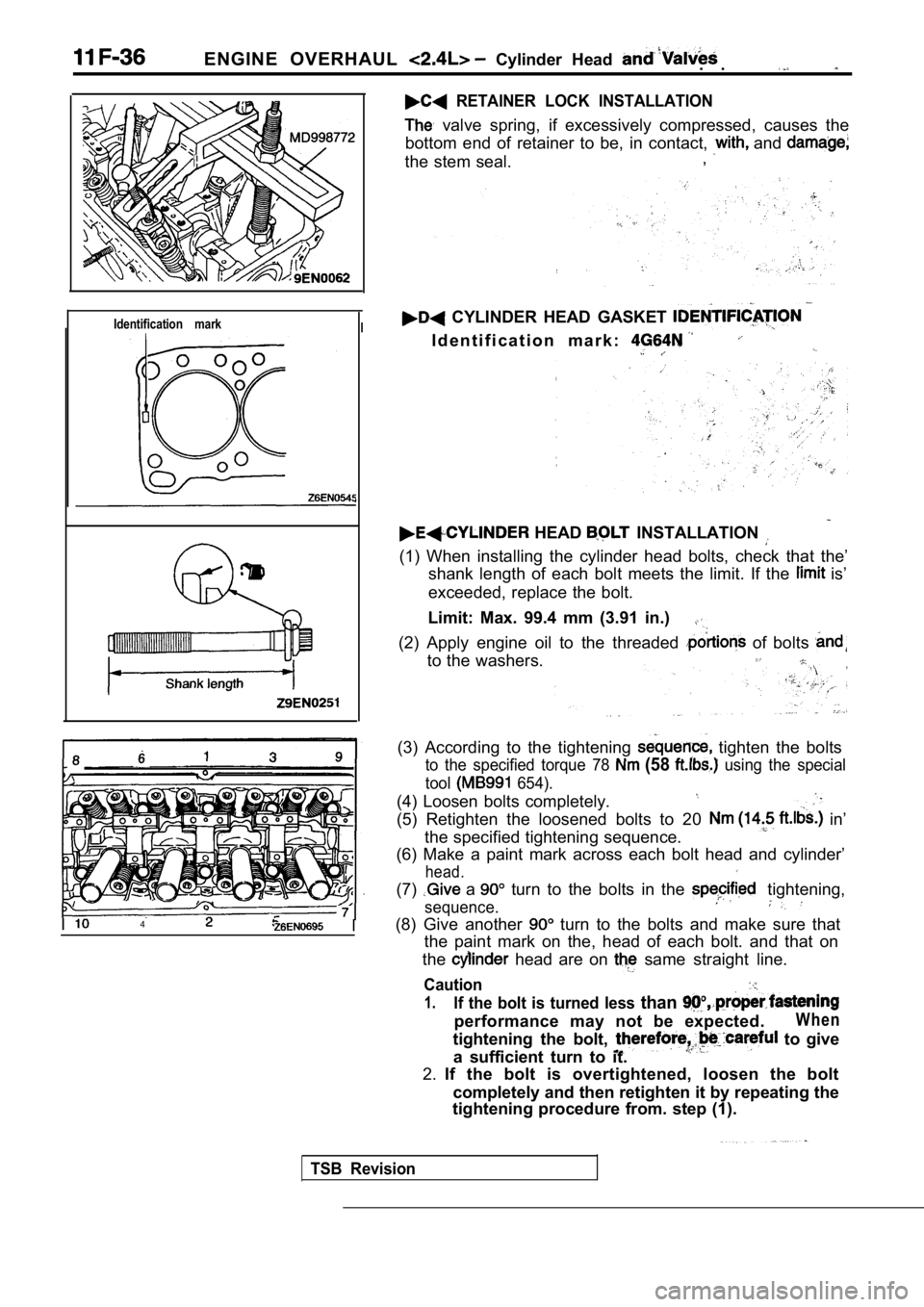
ENGINE OVERHAUL Cylinder Head . .
RETAINER LOCK INSTALLATION
valve spring, if excessively compressed, causes the
bottom end of retainer to be, in contact,
and
the stem seal. ,
Identification markI
I4
CYLINDER HEAD GASKET
I d e n t i f i c a t i o n m a r k :
HEAD INSTALLATION
(1) When installing the cylinder head bolts, check
that the’
shank length of each bolt meets the limit. If the
is’
exceeded, replace the bolt.
Limit: Max. 99.4 mm (3.91 in.)
(2) Apply engine oil to the threaded of bolts
to the washers.
(3) According to the tightening tighten the bolts
to the specified torque 78 (58 using the special
tool
654).
(4) Loosen bolts completely.
(5) Retighten the loosened bolts to 20 in’
the specified tightening sequence.
(6) Make a paint mark across each bolt head and cyl inder’
head.
(7) a turn to the bolts in the tightening,
sequence.
(8) Give another turn to the bolts and make sure that
the paint mark on the, head of each bolt. and that on
the
head are on same straight line.
Caution
1.If the bolt is turned less than
performance may not be expected.W h e n
tightening the bolt, to give
a sufficient turn to it.
2. If the bolt is overtightened, loosen the bolt
completely and then retighten it by repeating the
tightening procedure from. step (1).
TSB Revision
Page 355 of 2103
ENGINE OVERHAUL Shaft and Can
Case,
62
Crank pulley side
0
mm bolts
0
Oil pan viewed from lower side
(2) Secure the oil pump driven gear onto the left counterbal-
ance shaft by tightening the flange bolt to specified torque.
PLUG INSTALLATION
(1) Install a new O-ring to the of front case.
(2)Using the special tool, plug and tighten to speci-
fied torque.
OIL PAN INSTALLATION
(1) Clean both mating surfaces of oil pan and cylin der block.
(2) Apply a 4 mm in.) wide bead of sealant to the entire
circumference of the oil pan flange.
Specified sealant:
MITSUBISHI GENUINE PART No. or
equivalent
NOTE
(1) Be sure to install the oil pan quickly while th e sealant
is wet (within 15 minutes).
(2) After installation, keep the sealed area awayfrom
the oil and coolant for approx.
hour.
(3) Note the difference in bolt lengths at the loca tion shown.
TSB Revision