Page 160 of 2103
11ENGINE OVERHAUL Piston and
No.
Notch
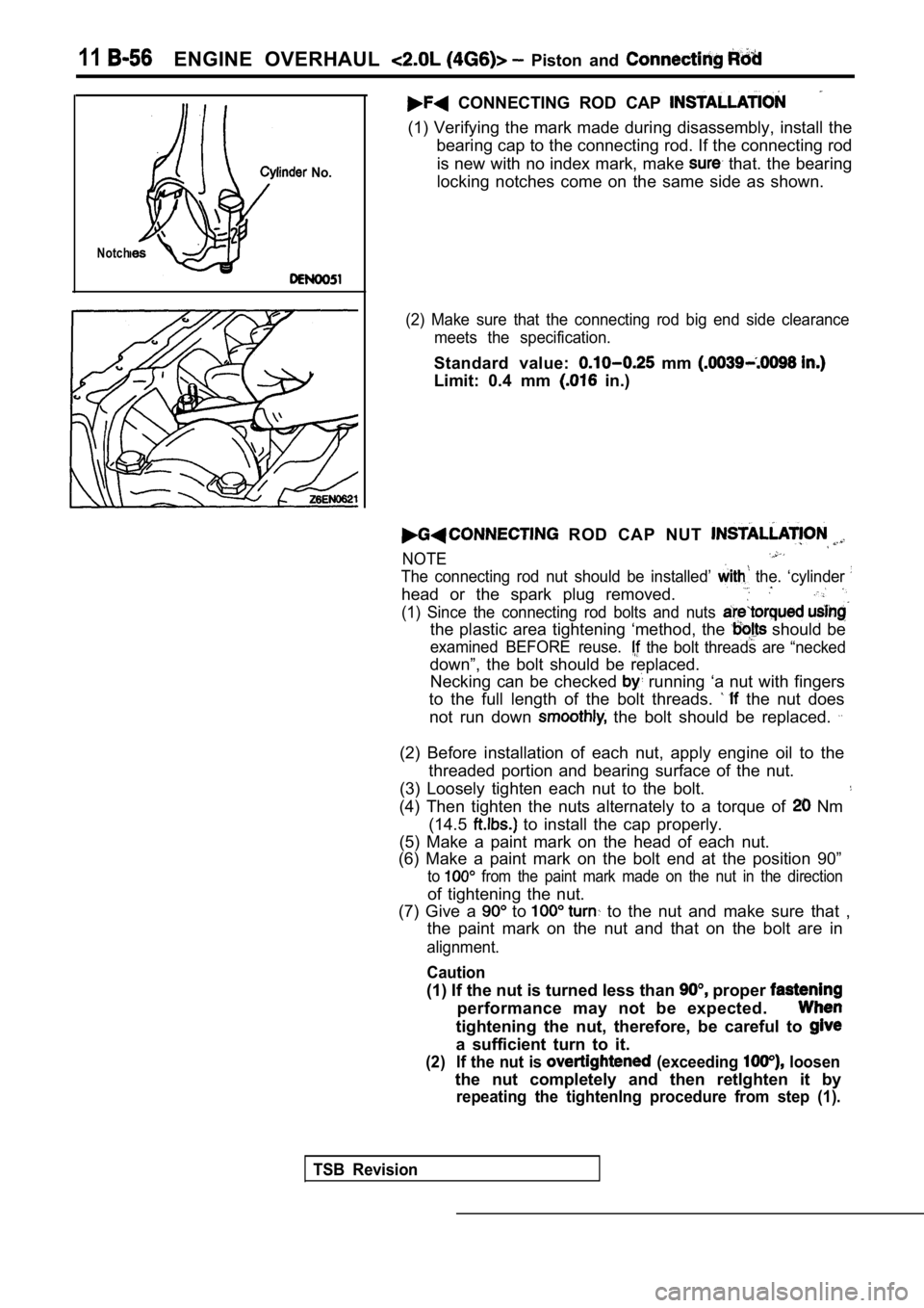
CONNECTING ROD CAP
(1) Verifying the mark made during disassembly, install the
bearing cap to the connecting rod. If the connectin g rod
is new with no index mark, make
that. the bearing
locking notches come on the same side as shown.
(2) Make sure that the connecting rod big end side clearance
meets the specification.
Standard value: mm
Limit: 0.4 mm in.)
ROD CAP NUT
NOTE
The connecting rod nut should be installed’ the. ‘cylinder
head or the spark plug removed.
(1) Since the connecting rod bolts and nuts
the plastic area tightening ‘method, the should be
examined BEFORE reuse. the bolt threads are “necked
down”, the bolt should be replaced. Necking can be checked
running ‘a nut with fingers
to the full length of the bolt threads.
the nut does
not run down
the bolt should be replaced.
(2) Before installation of each nut, apply engine o il to the
threaded portion and bearing surface of the nut.
(3) Loosely tighten each nut to the bolt.
(4) Then tighten the nuts alternately to a torque o f Nm
(14.5
to install the cap properly.
(5) Make a paint mark on the head of each nut.
(6) Make a paint mark on the bolt end at the positi on 90”
to from the paint mark made on the nut in the direction
of tightening the nut.
(7) Give a
to to the nut and make sure that ,
the paint mark on the nut and that on the bolt are in
alignment.
Caution
(1) If the nut is turned less than proper
performance may not be expected.
tightening the nut, therefore, be careful to
a sufficient turn to it.
(2) If the nut is (exceeding loosen
the nut completely and then retlghten it by
repeating the tightenlng procedure from step (1).
TSB Revision
Page 162 of 2103
ENGINE OVERHAUL Piston Rod
1I
PIN OIL CLEARANCE
(PLASTIGAGE METHOD)
(1) Remove oil from crankshaft pin and connecting rod
bearing.
(2) Cut the Plastigage to the same length as the width of
bearing and place it on crankshaft pin in parallel with
i t s a x i s .
(3) Install the connecting rod cap
tighten the
nuts to specified torque.
(4) Carefully remove the connecting rod cap.
(5) Measure the width of the Plastigage at its wide st part
by using a scale printed on the Plastigage package.
Standard value:,
mm
Limit: 0.1 mm in.)
TSB Revision
Page 167 of 2103
ENGINE OVERHAUL and
A
INSPECTION
O I L C L E A R A N C E
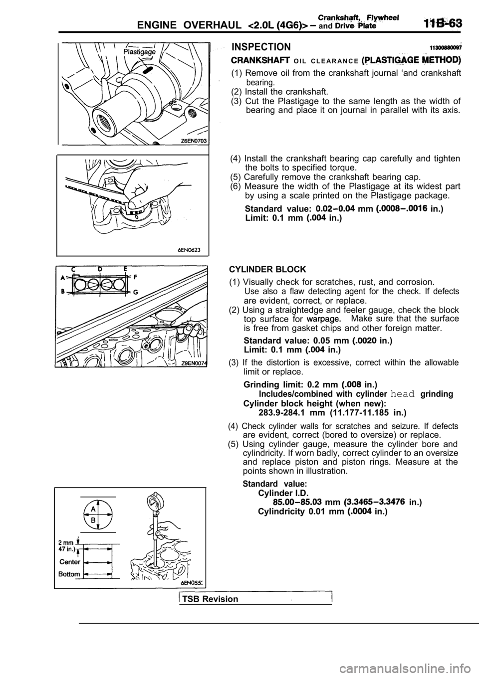
(1) Remove oil from the crankshaft journal ‘and crankshaft
bearing.
(2) Install the crankshaft.
(3) Cut the Plastigage to the same length as the wi dth of
bearing and place it on journal in parallel with it s axis.
(4) Install the crankshaft bearing cap carefully an d tighten
the bolts to specified torque.
(5) Carefully remove the crankshaft bearing cap.
(6) Measure the width of the Plastigage at its wide st part
by using a scale printed on the Plastigage package.
Standard value:
mm in.)
Limit: 0.1 mm
in.)
CYLINDER BLOCK (1) Visually check for scratches, rust, and corrosi on.
Use also a flaw detecting agent for the check. If d efects
are evident, correct, or replace.
(2) Using a straightedge and feeler gauge, check th e block
top surface for
Make sure that the surface
is free from gasket chips and other foreign matter.
Standard value: 0.05 mm
in.)
Limit: 0.1 mm
in.)
(3) If the distortion is excessive, correct within the allowable
limit or replace.
Grinding limit: 0.2 mm
in.)
Includes/combined with cylinder headgrinding
Cylinder block height (when new): 283.9-284.1 mm (11.177-11.185 in.)
(4) Check cylinder walls for scratches and seizure. If defects
are evident, correct (bored to oversize) or replace.
(5) Using cylinder gauge, measure the cylinder bore and
cylindricity. If worn badly, correct cylinder to an oversize
and replace piston and piston rings. Measure at the
points shown in illustration.
Standard value:
Cylinder I.D.
mm in.)
Cylindricity 0.01 mm
in.)
TSB Revision
Page 178 of 2103
Crankshaft
B E L T
ADJUSTMENT
Check the belt tension with the tension gauge, or check the
belt deflection by pressing the middle point of the belt by
a force of 98
(22 ibs.).
Standard value: Tension: 400
490 (90 110
Deflection
9.0 12.0 mm
GENERATOR BELT
1. Remove the under cover side panel (R.H.).
2. Loosen the generator pivot nut.
3. Loosen the lock nut.
4. Turn the adjusting screw to adjust
belt tension or
deflection to the standard
NOTE
When installing a new belt, apply 310
(70 ibs.) of tension’
for 5 minutes or more, and then apply the final ten sion.
Standard value:. . . .
items
Tension
(Ibs.)
When a new is
installed
When a belt is
Deflection
mm (in.)
value>
5. Tighten the generator pivot nut.
Tightening torque: 54 Nm
6. Tighten the lock nut.Tightening torque: 61 Nm (45
7. Install the under cover side panel (R.H.).
TSB Revision
Page 179 of 2103
ENGINE On-vehicle
Power
Powersteering oilpump pulleyTension
pulley
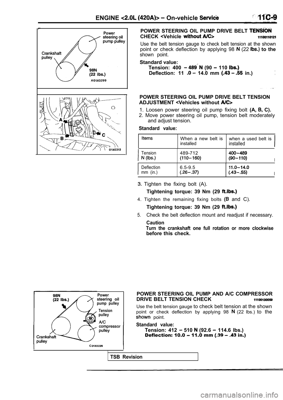
POWER STEERING OIL PUMP DRIVE BELT
CHECK
Use the belt tension gauge to check belt tension at the shown
point or check deflection by applying 98 (22 to the
shown point.
Standard value:
Tension: 400
(90 110
Deflection: 11 14.0 mm in.)
POWER STEERING OIL PUMP DRIVE BELT TENSION
ADJUSTMENT
1. Loosen power steering oil pump fixing bolt (A, C).
2. Move power steering oil pump, tension belt moder ately
and adjust tension.
Standard value:
When a new belt is when a used belt is
installedinstalled
Tension489-712
I
Deflection6.5-9.5
mm (in.)I
Tighten the fixing bolt (A).
Tightening torque: 39 Nm (29
4. Tighten the remaining fixing bolts and C).
Tightening torque: 39 Nm (29
5.Check the belt deflection mount and readjust if nec essary.
Caution
Turn the crankshaft one full rotation or more clock wise
before this check.
POWER STEERING OIL PUMP AND A/C COMPRESSOR
DRIVE BELT TENSION CHECK
Use the belt tension gauge to check belt tension at the shown
point or check deflection by applying 98
(22 Ibs.) to the
point.
Standard value:
Tension: 412 510 (92.6 114.6 Ibs.)
Deflection: 10.0
11.0 mm in.)
TSB Revision
Page 193 of 2103
ENGINECamshaft and
67
a
EXHAUST CAMSHAFT
CAMSHAFT
Use the special tool to the camshaft turning, and
then install the intake
camshaft, sprockets.
CYLINDER HEAD COVER INSTALLATION
Install the cylinder head cover assembly to the hea d and
tighten fasteners in sequence shown in figure. Tigh ten all
fasteners according to the
torque method.
(1) Tighten to 4.5 Nm (3.3
(2) Tighten to 9.0 Nm (6.6
(3) Tighten to 12 Nm (6.9
TSB Revision
Page 202 of 2103
E N G I N E Cylinder Head
Unstretched bolt
‘Location of 110 mm (4.330 in.) short bolts.Step 4
Painted marks
Projection
Water outlet fitting
INSTALLATION SERVICE POINTS
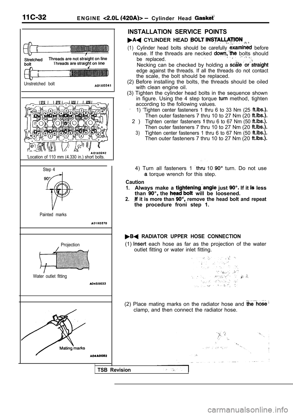
CYLINDER HEAD
(1)Cylinder head bolts should be carefully before
reuse. If the threads are necked bolts should
be replaced.
Necking can be checked by holding a
edge against the threads. If all the threads do not contact
the scale, the bolt should be replaced.
(2) Before installing the bolts, the threads should be oiled
with clean engine oil.
(3) Tighten the cylinder head bolts in the sequence shown
in figure. Using the 4 step torque
method, tighten
according to the following values.
1) ‘Tighten center fasteners 1 thru 6 to 33 Nm (25
Then outer fasteners 7 thru 10 to 27 Nm (20
2 )Tighten center fasteners thru 6 to 67 Nm (50
Then outer fasteners 7 thru 10 to 27 Nm (20
3)Tighten center fasteners 1 thru 6 to 67 Nm (50
Then outer fasteners 7 thru 10 to 27 Nm (20
4) Turn all fasteners 1 10 turn. Do not use
torque wrench for this step.
Caution
1.Always make a just If it less
than
the will be loosened.
2. it is more than remove the head bolt and repeat
the procedure froni step 1.
RADIATOR UPPER HOSE CONNECTION
(1) each hose as far as the projection of the water
outlet fitting or water inlet fitting.
(2) Place mating marks on the radiator hose and
clamp, and then connect the radiator hose.
TSB Revision
Page 206 of 2103
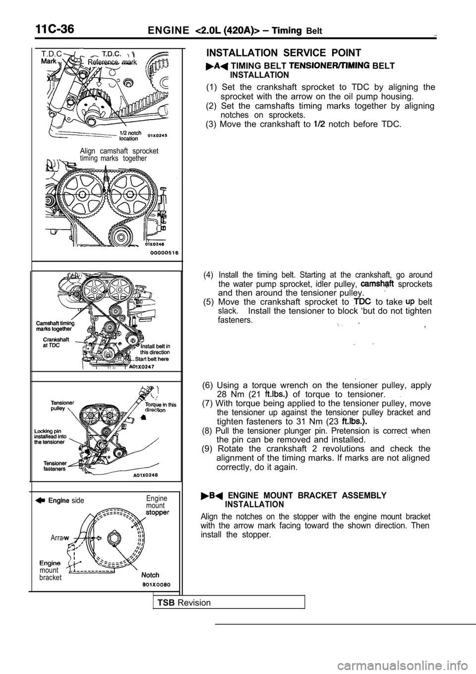
ENGINE Belt
Reference mark
T.D.C.
Align camshaft sprockettimingmarks together
side
Arra
mount
bracket Engine
mount
INSTALLATION SERVICE POINT
TIMING BELT BELT
INSTALLATION
(1) Set the crankshaft sprocket to TDC by aligning the
sprocket with the arrow on the oil pump housing.
(2) Set the camshafts timing marks together by alig ning
notches on sprockets.
(3) Move the crankshaft to notch before TDC.
(4) Install the timing belt. Starting at the crankshaft, go around
the water pump sprocket, idler pulley, sprockets
and then around the tensioner pulley.
(5) Move the crankshaft sprocket to to take belt
slack.Install the tensioner to block ‘but do not tighten
fasteners.
(6) Using a torque wrench on the tensioner pulley, apply
28 Nm (21
of torque to tensioner..
(7) With torque being applied to the tensioner pull ey, move
the tensioner up against the tensioner pulley brack et and
tighten fasteners to 31 Nm (23
(8) Pull the tensioner plunger pin. Pretension is correct when
the pin can be removed and installed.
(9) Rotate the crankshaft 2 revolutions and check t he
alignment of the timing marks. If marks are not ali gned
correctly, do it again.
ENGINE MOUNT BRACKET ASSEMBLY
INSTALLATION
Align the notches on the stopper with the engine mo unt bracket
with the arrow mark facing toward the shown direction. Then
install the stopper.
TSB Revision