Page 1272 of 2103
AUTOMATIC TRANSAXLE
OVERHAUL
Apply automatic transmission fluid to the bolts and tighten
the
to the specified torque sequence shown in
the illustration.
TSB Revision
Page 1286 of 2103

AUTOMATIC TRANSAXLE
OVERHAUL
General
Precautions to be taken when disassembling and the
Because the automatic transaxle is of component parts of especially high degree of
precision, these parts should be very carefully han dled during disassembly and assembly so as not
to scar or scratch them.
A rubber mat should be placed on the and it should always be kept clean.
During disassembly, cloth gloves or shop towels, sh ould not be used.
such items must be used,
either use articles made of nylon, or use paper tow els.
All disassembled parts must be thoroughly cleaned.
Metal parts may be cleaned with ordinary but must thoroughly air dried.
Clean the clutch disc, resin thrust plate and rubbe r parts by using ATF (automatic transmission fluid) ,
being very careful that dust, dirt, etc. do not adhere to them.
Do not reuse gaskets, oil seals, or, rubber parts.
Replace such parts with new ones at every reassembl y. The oil’ gauge need not
be replaced.
Do not use grease other than petrolatum jelly.
Apply ATF to friction components, rotating
and sliding parts before installation.
A new clutch disc should be immersed in ATF for at least two hours before installation.
Do not apply sealer or adhesive to gaskets.
When a bushing must be replaced, replace the assemb ly in which it is incorporated:,
If the transaxle main unit is damaged, also disasse
mble and clean the ‘cooler system.,
TSB Revision
Page 1313 of 2103

A U T O M A T I C T R A N S A X L E
OV E R HAUL -Transaxle
I
68
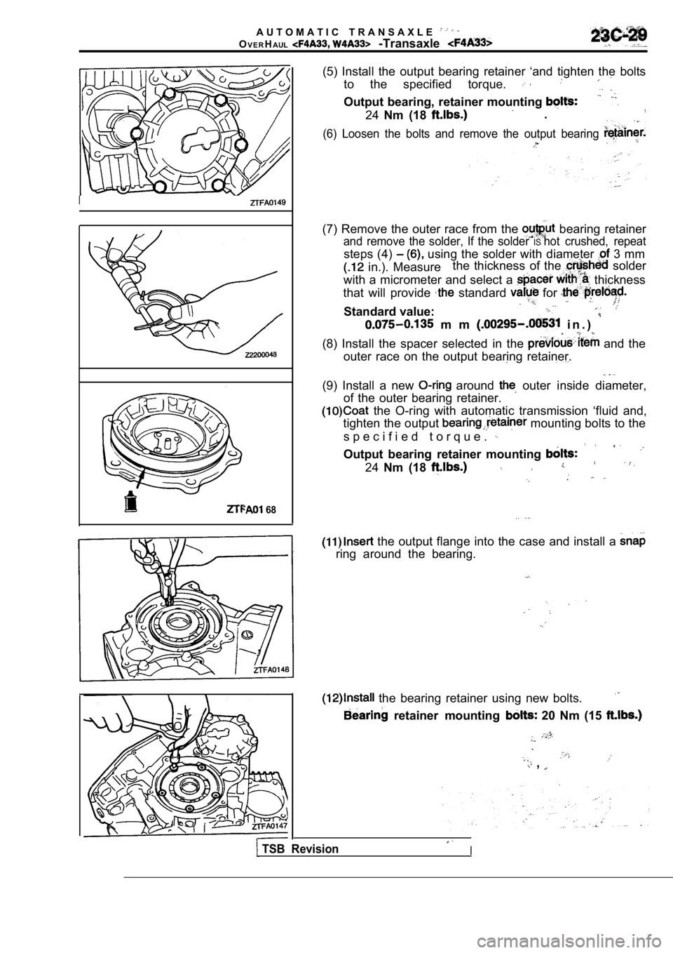
(5) Install the output bearing retainer ‘and tighte n the bolts
to the specified torque.
Output bearing, retainer mounting
24 Nm (18 .,
(6) Loosen the bolts and remove the output bearing
(7) Remove the outer race from the bearing retainer
and remove the solder, If the solder IShot crushed, repeat
steps (4) using the solder with diameter 3 mm
in.). Measure the thickness of the solder
with a micrometer and select a
thickness
that will provide
standard for
Standard value:
m m i n . ) .
(8) Install the spacer selected in the and the
outer race on the output bearing retainer.
(9) Install a new around outer inside diameter,
of the outer bearing retainer.
the O-ring with automatic transmission ‘fluid and,
tighten the output
mounting bolts to the
s p e c i f i e d t o r q u e .
Output bearing retainer mounting
24 Nm (18
the output flange into the case and install a
ring around the bearing.
the bearing retainer using new bolts.
retainer mounting 20 Nm (15
,
TSB RevisionI
Page 1324 of 2103
AUTOMATIC TRANSAXLE
OVERHAUL
-Transaxle
a new O-ring on the rear bearing retainer,
coat the O-ring with automatic transmission fluid,; then
install in the transaxle case and tighten the mount ing
bolts to the specified torque.
Differential rear bearing
mounting
35 Nm (26
the front bearing cap and tighten the bolts to the
specified torque..
Differential front bearing cap mounting bolts: 70 Nm (51
the differential cover and a new gasket.
Differential cover mounting bolts: 11 Nm (8
the detent plate.
Detent plate mounting bolt: 11 Nm (8
,,
a new O-ring on the manual control shaft assembly,
coat the O-ring with automatic
and then
insert into the transaxle case.
the groove in the manual control shaft and the set
screw hole; then install the set screw.
Manual
shaft set screw: 9 (7
the parking roller support.
Parking roller support bolts: 24 Nm (18
TSB RevisionI
Page 1328 of 2103
AUTOMATIC TRANSAXLE
OVERHAUL
Transaxle
the lock nut by hand until it touches the
Then, use torque wrench the lock nut
specified torque.
Lock nut: 29 Nm (21
Caution Caution
The lock nut may turn- with the The lock nut may turn- with the
tightened quickly, or tightened quickly, or
wrench.
wrench.
(g)Remove the special tool for securing the piston.
the plug to the pressure outlet and tight-
en to the specified torque.
ring. the
servo switch and fasten with a snap
,
the oil pump drive hub with automatic transmission
,
fluid and install the torque. converter. in firmly
that dimension A in the diagram is at the standard value.
Standard value: 16.3
TSB Revision
Page 1329 of 2103
-Transaxle
COMPONENTS
Lubricate all internal
parts with automatic
Itransmission fluid
during reassembly.
22200100127
1.Torque converter
assembly
Thrust washer 5.Front clutch assembly6.Thrust race
7.Thrust bearing 8.Thrust washer
9. Rear clutch assembly
10. Thrust bearing
11.Rear clutch hub
12. Thrust bearing
13. Thrust race 14. band15. drum
16.Snap ring
17. Center support
s p r i n g ,
1 9 . R e t u r n
20.Pressure plate
21.Brake
22.Brake23.Reaction plate:,.
24. Reverse sun gear25. Thrust bearing 26.Thrust race 27. sun 28. carrier. 29.Thrust bearing,30.Output flange..
TSBRevision
Page 1355 of 2103
AUTOMATIC TRANSAXLE
OVERHAUL -Transaxle
Detent plate
a new O-ring on the, differential retainer,
coat the O-ring with then
install in the transaxle case and tighten the mount ing
bolts to the specified torque. ,
Differential rear bearing retainer’ mounting
35
Nm (26
,
the front bearing cap and tighten the the
specified torque.
Differential front bearing cap mounting
70Nm (51
the differential cover and a’ new gasket,
D i f f e r e n t i a l
the detent . .
Detent plate mounting bolt: 11 Nm(8
a new O-ring on the manual control shaft
coat the O-ring automatic transmission fluid and then
insert into the transaxle case.
the groove in the manual control shaft and the set
screw hole; then install the set screw.
Manual control ‘shaft,
the parking roller support.
Parking roller support
bolts:
24 Nm (18
evision
Page 1359 of 2103

AUTOMATIC TRANSAXLE
OVERHAUL -Transaxle
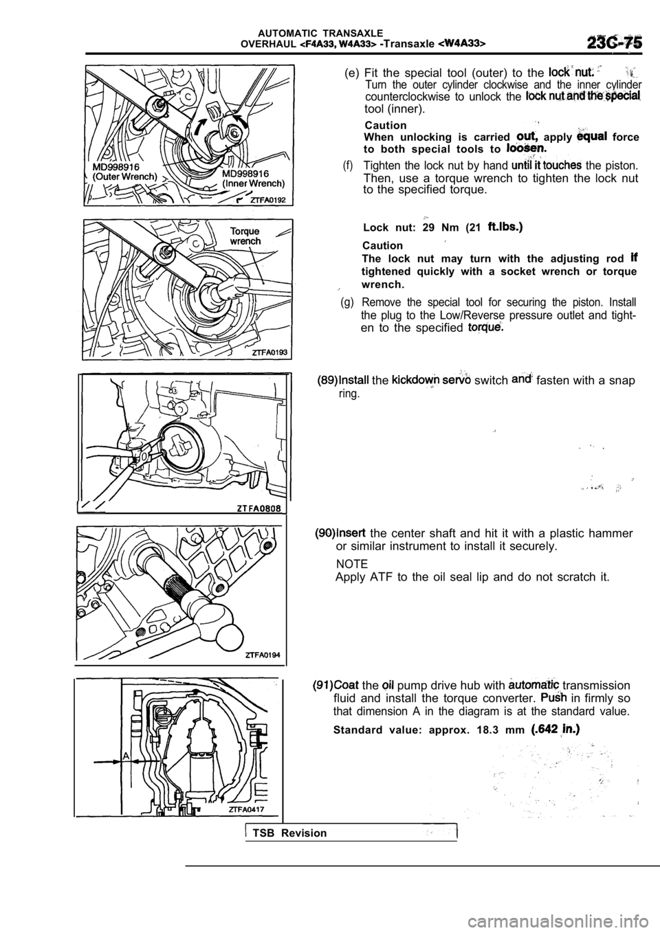
(e) Fit the special tool (outer) to the
Turn the outer cylinder clockwise and the inner cyl inder
counterclockwise to unlock the
tool (inner).
Caution
When unlocking is carried
apply force
to both special tools to
(f)Tighten the lock nut by hand the piston.
Then, use a torque wrench to tighten the lock nut
to the specified torque.
Lock nut: 29 Nm (21
Caution
The lock nut may turn with the adjusting rod
tightened quickly with a socket wrench or torque
wrench.
(g) Remove the special tool for securing the piston. In stall
the plug to the Low/Reverse pressure outlet and tight-
en to the specified
the switch fasten with a snap
ring.
the center shaft and hit it with a plastic hammer
or similar instrument to install it securely.
NOTE
Apply ATF to the oil seal lip and do not scratch it .
the pump drive hub with transmission
fluid and install the torque converter.
in firmly so
that dimension A in the diagram is at the standard value.
Standard value: approx. 18.3 mm
TSB Revision