Page 712 of 2103
Water Hose and
ENGINE COOLING and Engine>
WATER HOSE AND WATER PIPE
ENGINE (TURBO) AND ENGINE>1 4 1 0 0 3 3 0 2 4 5
REMOVAL AND INSTALLATION
Engine (Turbo)>
Pre-removal and Post-installation Operationl
Engine Coolant Draining and Supplying (Refer to
GROUP 00 Maintenance Service.)
l Air Hose (C) Removal and Installation (Refer to
GROUP 15
Charge Air Cooler.)
l Turbocharger Removal and Installation (Refer toGROUP 15 Exhaust Manifold.)
11
2417
24 Nm17
48Nm35
3
Specified Sealant:
or equivalent
58
Removal steps
1. Radiator upper hose connection
2. Radiator lower hose connection
3. Water hose4. Heater hose connection
5. Water hose
6. Thermostat case assembly
8. Water pipe assembly
9. Water hose
10. Water hose
11. Heater hose connection
12. inlet pipe assembly
hose
Water hose16. Water pipe assembly (A)17. Water pipe assembly (B)
18. Water
19. Water pipe (C)20. Joint
TSB Revision
Page 713 of 2103
Water Hose and Water Pipe
ENGINE COOLING and Engine>
Engine>
Pre-removal and Post-installation Operation“(1) Engine Coolant Draining and Supplying (Refer toGROUP 00 Maintenance Service.)(2) Air Cleaner Removal and Installation
(3) Exhaust Manifold Removal and
(Refer to GROUP 15 Exhaust Manifold.)
Specified Sealant:Mitsubishi Genuine Part No. or equivalent
Removal steps
1. Radiator upper hose connection 2. Radiator lower hose 3. Thermostat case assembly 4. O-ring
5. Water hose 6. Water hose
7. Heater hose connection
8. Water inlet pipe assembly 9. o-ring
TSB Revision
Page 721 of 2103
INTAKE AND EXHAUST Intake Manifold Engine
REMOVAL AND INSTALLATION
Operationl Residual Fuel Pressure Releasing(Refer to GROUP Service.)l Engine Coolant Draining(Refer to GROUP Service.)l Reservoir Assembly Removal with Auto-Cruise
2.9
Post-installation Operationl Reservoir Assembly Installation
l Engine Coolant Supplying (Refer to GROUP Service.)l Accelerator Cable Adjustment (Refer to GROUP 17 On-vehicle Service.)
3.92 . 9
O-ring
Engineoil
Removalsteps
1. Air intake hose2.Breather hose
3. Accelerator cable connection
4. Clip5. MAP sensor connector
6. Charge temperature sensor connector
7. Vacuum hose connection
8.TPS connector9. motor connector 10.
wiring harness11. connection
12. PCV hose assembly 13. Vacuum hose connection14. Brake booster hose
connection
15. pipe connection
16. fuel hose connection
TSB Revision
Page 725 of 2103

INTAKE AND EXHAUST Intake Manifold Engine
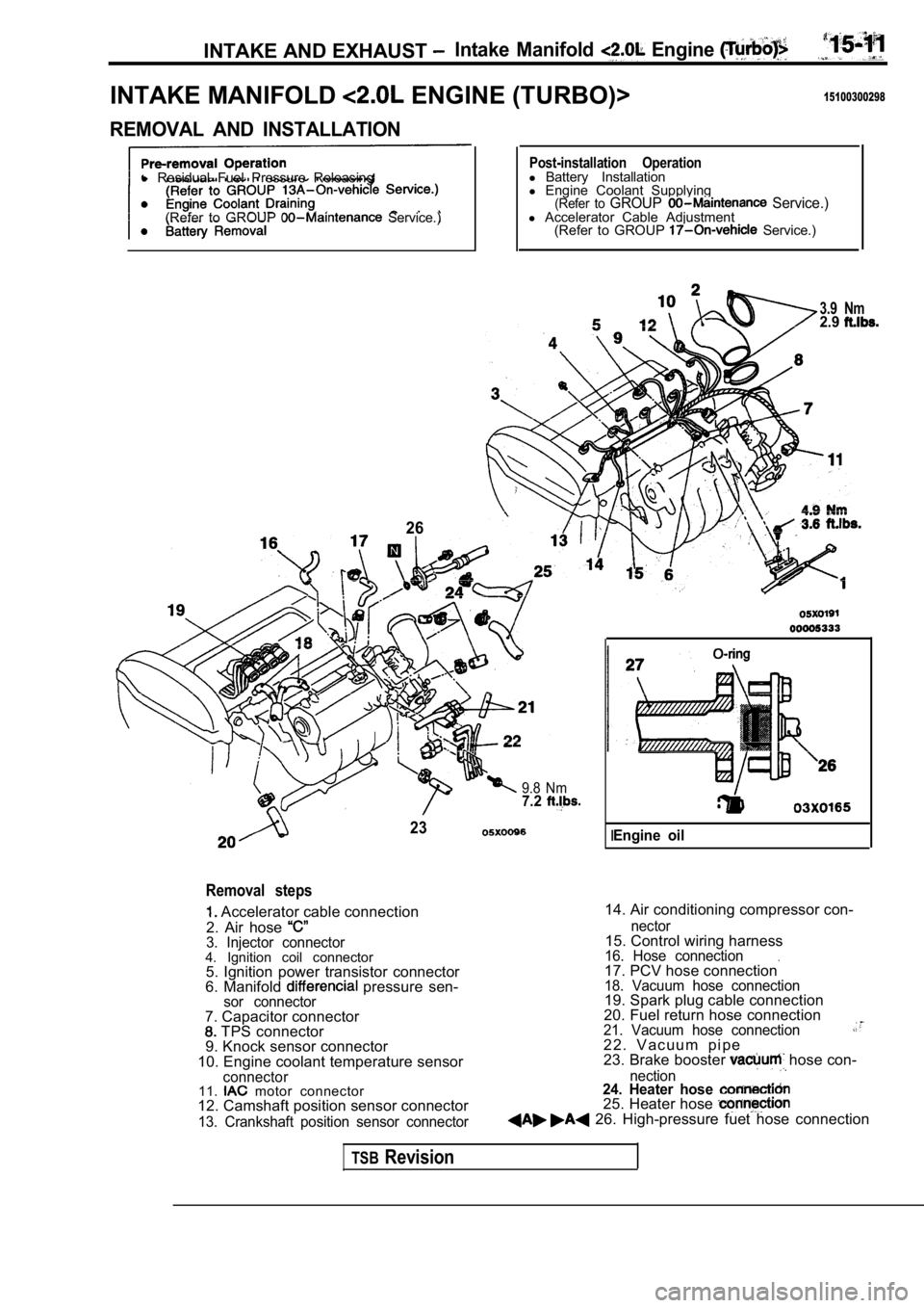
INTAKE MANIFOLD ENGINE (TURBO)>15100300298
REMOVAL AND INSTALLATION
l Residual Fuel Pressure Releasing
(Refer to GROUP
Service.)
26
Post-installation Operationl Battery Installation
l Engine Coolant Supplying
(Refer to GROUP Service.)l Accelerator Cable Adjustment
(Refer to GROUP Service.)
3.9 Nm2.9
9.8 Nm7.2
23
Removal steps
Accelerator cable connection
2. Air hose
3. Injector connector4. Ignition coil connector 5. Ignition power transistor connector
6. Manifold
pressure sen-sor connector
14. Air conditioning compressor con-
7. Capacitor connector
TPS connector
9. Knock sensor connector
10. Engine coolant temperature sensor
connector11. motor connector
12. Camshaft position sensor connector
13. Crankshaft position sensor connector nector
15. Control wiring harness16. Hose connection.17. PCV hose connection18. Vacuum hose connection19. Spark plug cable connection
20. Fuel return hose connection
21. Vacuum hose connection2 2 . V a c u u m p i p e
23. Brake booster hose con-
nection24. Heater hose 25. Heater hose 26. High-pressure fuet hose connection
IEngine oil
TSBRevision
Page 731 of 2103
INTAKE, AND EXHAUST Exhaust Manifold Engine
EXHAUST MANIFOLD ENGINE (NON-TURBO)>’
REMOVAL AND INSTALLATION
and Post-installation Operationl Engine Coolant Draining and (Refer to GROUP
3.9 Nm2.9
6
Removal steps
1. Air intake hose
2. Radiator upper hose connection
3. Air hose connection
4. Control wiring harness connection
5. Water pipe assembly
6. Engine oil level gauge
Nm
44Nm33
,
7.Heat protector6.Engine hanger9. Front exhaust connection10.Heatprotector11. Exhaust 12. Exhaust manifold gasket
TSB RevisionI
Page 732 of 2103
INTAKE AND EXHAUST Exhaust Manifold
E X H A U S T M A N I F O L D E N G I N E ( T U R B O ) >
REMOVAL AND INSTALLATION
Pre-removal and Post-installation OperationEngine Coolant Draining and Refilling
l Engine Oil Draining and Refilling
(Refer to GROUP 00
Maintenance Service.)
Nm
12-15 Nm8.8-11- - 1 6 ’
3
. .
Removal steps
1. Condenser fan motor assembly with air conditioning>
2. Heated oxygen sensor
3. Engine oil level gauge guide
4. Air cleaner and air intake hose
assembly5. Air hose (A) connection
6. Water hose connection
7. Water hose connection
8. Oil pipe (A) connection 9. Heat protector
A)
10. Heat protectorB)
11. Engine hanger
12. Front exhaust pipe connection 13. Flange bolts 14. Flange 15.
Coned disc spring .16. Exhaust -manifold17.Exhaust manifold gasket Ring19. Gasket (A)
TSB Revision
Page 734 of 2103

INTAKE AND EXHAUST Exhaust Manifold ENGINE (Turbo)>
Identification holeExhaust
manifold
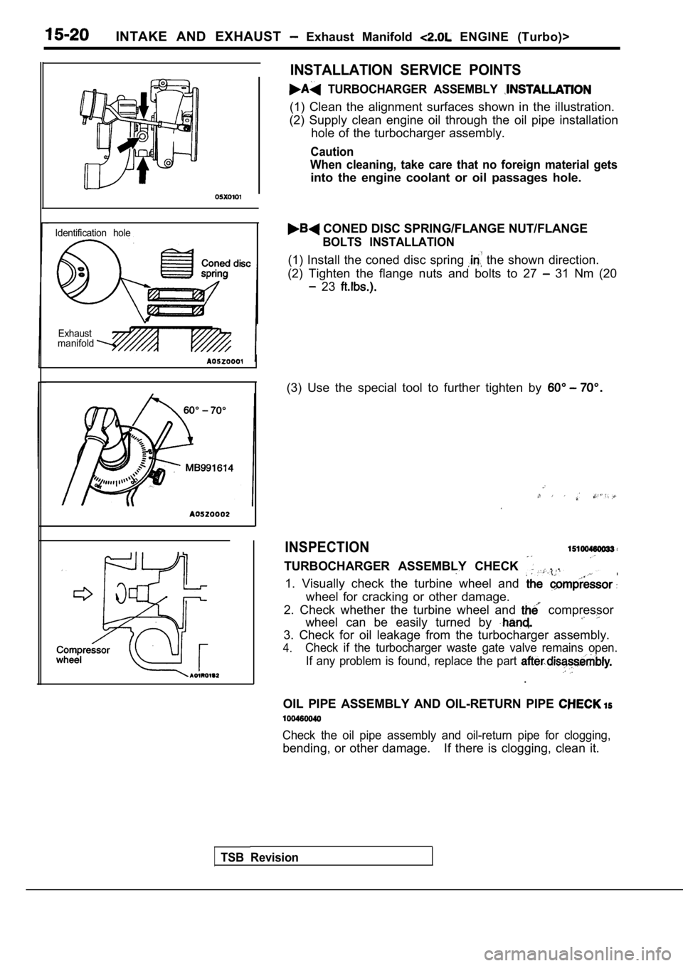
INSTALLATION SERVICE POINTS
TURBOCHARGER ASSEMBLY
(1) Clean the alignment surfaces shown in the illus tration.
(2) Supply clean engine oil through the oil pipe in stallation
hole of the turbocharger assembly.
Caution
When cleaning, take care that no foreign material g ets
into the engine coolant or oil passages hole.
CONED DISC SPRING/FLANGE NUT/FLANGE
BOLTS INSTALLATION
(1) Install the coned disc spring the shown direction.
(2) Tighten the flange nuts and bolts to 27
31 Nm (20
23
(3) Use the special tool to further tighten by
INSPECTION
TURBOCHARGER ASSEMBLY CHECK . .
1. Visually check the turbine wheel and
wheel for cracking or other damage.
2. Check whether the turbine wheel and
compressor
wheel can be easily turned by
3. Check for oil leakage from the turbocharger asse mbly.
4.Check if the turbocharger waste gate valve remains open.
If any problem is found, replace the part
.
OIL PIPE ASSEMBLY AND OIL-RETURN PIPE
Check the oil pipe assembly and oil-return pipe for clogging,
bending, or other damage. If there is clogging, clea n it.
TSB Revision
Page 741 of 2103

CONTENTS
AUTO-CRUISE CONTROL SYSTEM
. . . . . . . . . . . . . . . . . . . . . . . . . . . . . . . . . . . . .7
AUTO-CRUISE CONTROL* . . . . . . . . . . . . . . 40
GENERAL INFORMATION . . . . . . . . . . . . . . . . 7
ON-VEHICLE SERVICE. . . . . . . . . . . . . . . . . 33
Auto-cruise Control Cable Check and
Adjustment . . . . . . . . . . . . . . . . . . . . . . . . . . . . . .
33
Auto-cruise Control Component Check . . . . . 37
Auto-cruise Control System Operation Check
. . . . . . . . . . . . . . . . . . . . . . . . . . . . . . . . . . . . . . . . .
35
SERVICE SPECIFICATIONS . . . . . . . . . . . . . 8
SPECIAL TOOLS . . . . . . . . . . . . . . . . . . . . . . . . 8
TROUBLESHOOTING
ENGINE (NON-TURBO)> . . . . . . . . . . . 9
TROUBLESHOOTING
(TURBO) AND ENGINE> . . . . .
EMISSION CONTROL’ SYSTEM
. . . . .
CATALYTIC . . . . . . . . . . . . . .
General Information . . . . . . . . . . . . . . . . . . 57
EVAPORATIVE EMISSION .
SYSTEM. . . . . . . . . . . . . . . .
Air Conditioning . . . . . . . . . . . . . . . . . . . 52
Component Location
. . . . . . . . . . . . . . . . . .
Engine Coolant Temperature Sensor
Intake Air Temperature Sensor . . . . . . . . . . . . 52
WARNINGS REGARDING SERVICING OF SUPPLEMENTAL RESTRA INT SYSTEM (SRS) EQUIPPED
WARNING!
(1) Improper serviceor maintenance of any component of the or any SRS-related can to injuryorcleathtoservicepersonnel (from inadvertentfiring the SRS inoperative).
(2) Service or maintenance of any SRS component or SRS-related component must be performed only
MITSUBISHI dealer.
(3) MITSUBISHI dealer personnel must thoroughly rev iew this manual, and especially its GROUP
Restraint System (SRS) and GROUP 00 Maintenance Service, before any service or maintenance of any
componentof the SRS or any SRS-related component.
NOTEJhe includes the following components: warning light, air bag module, clock components (that may have to be removed/installed in connection with or areIndicated in the table of contents by an asterisk