Page 663 of 2103

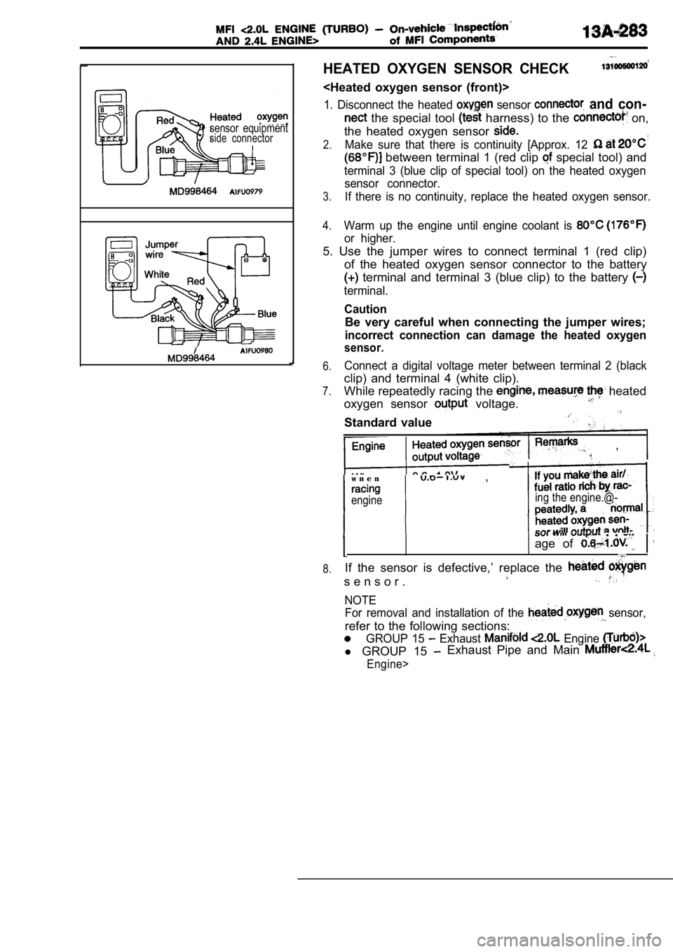
sensor equipmentside connector
HEATED OXYGEN SENSOR CHECK
1. Disconnect the heated sensor and con-
the special tool harness) to the on,
the heated oxygen sensor
2.Make sure that there is continuity [Approx. 12
between terminal 1 (red clip special tool) and
terminal 3 (blue clip of special tool) on the heate d oxygen
sensor connector.
3.If there is no continuity, replace the heated oxyge n sensor.
4.Warm up the engine until engine coolant is
or higher.
5. Use the jumper wires to connect terminal 1 (red clip)
of the heated oxygen sensor connector to the batter y
terminal and terminal 3 (blue clip) to the battery
terminal.
Caution
Be very careful when connecting the jumper wires;
incorrect connection can damage the heated oxygen
sensor.
6.
7.
8.Connect a digital voltage meter between terminal 2 (black
clip) and terminal 4 (white clip).
While repeatedly racing the
heated
oxygen sensor
voltage.
Standard value
,
w n e n ,
engineing the engine.@-
. .
age of
If the sensor is defective,’ replace the
s e n s o r .
NOTEFor removal and installation of the
sensor,
refer to the following sections:
GROUP 15 Exhaust Engine
l GROUP 15 Exhaust Pipe and Main
Engine>
Page 665 of 2103
RESISTOR CHECK Engine (Turbo)>;
T e r m i n a l s
1. Disconnect the resistor connector.
2. Measure the resistance between terminals.
Measuring terminalsResistance
4-3
5-3
6-3
3.
If the resistance is out of specification, replace the resistor.
ai r
I D L E A I R MO T O R )
CHECK Engine (Turbo
1. Check to be sure that the engine coolant tempera ture
is
or below.
NOTE
Disconnecting the engine coolant temperature sensor
connector and connecting the harness-side of the co nnec-
tor to another engine coolant temperature sensor th at
is at
or below is also okay.
2. Check that the operation sound of the stepper mo tor
can be heard after the ignition is ON (but without
starting the motor), then
3.If the operation sound cannot be heard, check the
motor’s activation circuit.
If the circuit is normal, it is probable that there, is
tion of the stepper of the engine module.
Page 691 of 2103

CONTENTS
GENERAL INFORMATION. . . . . . . . . . . . . . . . . .2SERVICE SPECIFICATIONS . . . . . . . . . . . . . . . . . 3
LUBRICANT3THERMOSTAT. . . . . . . . . . . . . . . . . . . . . . . . . . . .13. . . . . . . . . . . . . . . . . . . . . . . . . . . . . . .
ON-VEHICLE SERVICE. . . . . . . . . . . . . . . . . . . . .7TROUBLESHOOTING. . . . . . . . . . . . . . . . . . . . . . .4
Engine Coolant Concentration Test. . . . . . . . . . . .7.
Engine Coolant Leak Check . . . . . . . . . . . . . . . . . .
7WATER HOSE ‘AND PIPE
. . . . . . . . .
Engine Coolant Replacement. . . . . . . . . . . . . . . . .7 AND
Radiator Cap Valve Opening Pressure CheckENGINE>. . . . . . . . . . . . . . . .. . . . . . . . . . . . . . . . . .22
. . . . . . . . . . . . . . . . . . . . . . . . . . . . . . . . . . . . . . . . . . . . .7WATER PUMP
RADIATOR. . . . . . . . . .18. . . . . . . . . . . . . . . . . . . . . . . . . . . . . . . . .8 ENGINE (NON-TURBO)>
ENGINE (TURBO) AND , , S E A L A N T
. . . . . . . . . . . . . . . . . . . . . . . . . . . . . . . . . .3ENGINE>. . . . . . . . . . . . . . . . . . . . . . . . . . . . . . .18
Page 692 of 2103
14-2ENGINE COOLING General Information
GENERAL INFORMATION , ,
The cooling system is designed to keep every partthat the heat absorbed by the coolant may be of the engine at appropriate temperature in diated into the air.
er condition the engine may be operated.
The cooling of the water-cooled, pressureThe water pump is of the centrifugal type and is
driven by the
the
forced circulation type in which the water pump crankshaft. .
pressurizes coolant and circulates it throughout th e
engine: If the coolant temperature exceeds the
scribed temperature, the thermostat opens to circu-
late the coolant through the radiator as well so
and is cooled the
CONSTRUCTION DIAGRAM
Engine (Non-turbo)>
Radiator
Radi
.
oil cooler hose and pipe
Engine (Turbo)>
Radiator fan assembly
(Air cooled) oil cooler hose and pipetank
TSB Revision
Page 693 of 2103
G e n e r a l
ENGINE COOLING
Engine>
Radiator fan assemblyReserve tank
(Airoilcooler
cooled) oil cooler hose and pipe
SERVICE SPECIFICATIONS
ItemsStandard valueLimit
ThermostatValve opening temperature of Engine (Non-turbo)90.5 (195) thermostat Engine (Turbo) and Engine 82 (180)
Full-opening temperature of Engine (Non-turbo)
102 (216)
thermostat
Engine (Turbo) and Engine95 (203),
Radiator cap valve opening pressure (psi) Engine (Non-turbo)9 4 - 1 2 2 ( 1 4 - 1 8 )
Engine (Turbo) and Engine
LUBRICANT
ItemQuantity
Engine coolant HIGH QUALITY ETHYLENE GLYCOL ANTIFREE ZE COOLANT7.0 (7.4)
SEALANT
ItemSpecified sealant,
Thermostat case Engine (Turbo) and Engine>
Mitsubishi Genuine Parts No. or equivalent:
TSB Revision
Page 694 of 2103

E N G I N E C O O L I N G
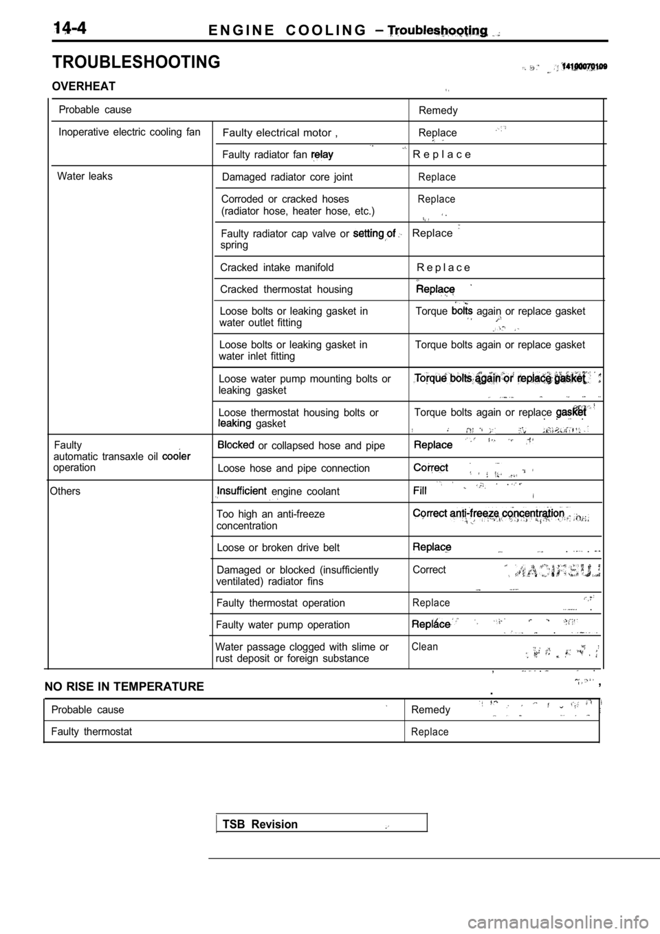
TROUBLESHOOTING
OVERHEAT
Probable cause
Inoperative electric cooling fan
Water leaks
Faulty electrical motor ,
Faulty radiator fan
Damaged radiator core joint
Corroded or cracked hoses
(radiator hose, heater hose, etc.)
Remedy
Replace
R e p l a c e
Replace
Replace
.
Faulty radiator cap valve or Replace
spring
Cracked intake manifold
Cracked thermostat housing
R e p l a c e
Loose bolts or leaking gasket in
water outlet fitting Torque again or replace gasket
Loose bolts or leaking gasket in
water inlet fitting Torque bolts again or replace gasket
Faulty Loose water pump mounting bolts or
leaking gasket
Loose thermostat housing bolts or
gasket
automatic transaxle oil
operation
Others
or collapsed hose and pipe
Loose hose and pipe connection
engine coolant
Too high an anti-freeze
concentration
Torque bolts again or replace . . .
.
Loose or broken drive belt
Damaged or blocked (insufficiently
ventilated) radiator fins
Faulty thermostat operation. .
Correct
Replace .
Faulty water pump operation .
Water passage clogged with slime orClean
rust deposit or foreign substance, . .
NO RISE IN TEMPERATURE
,
.
Probable cause
Faulty thermostatRemedy
Replace
TSB Revision
Page 697 of 2103

ENGINE COOLING On-vehicle Service
Engine (Turbo) and
ON-VEHICLE SERVICE
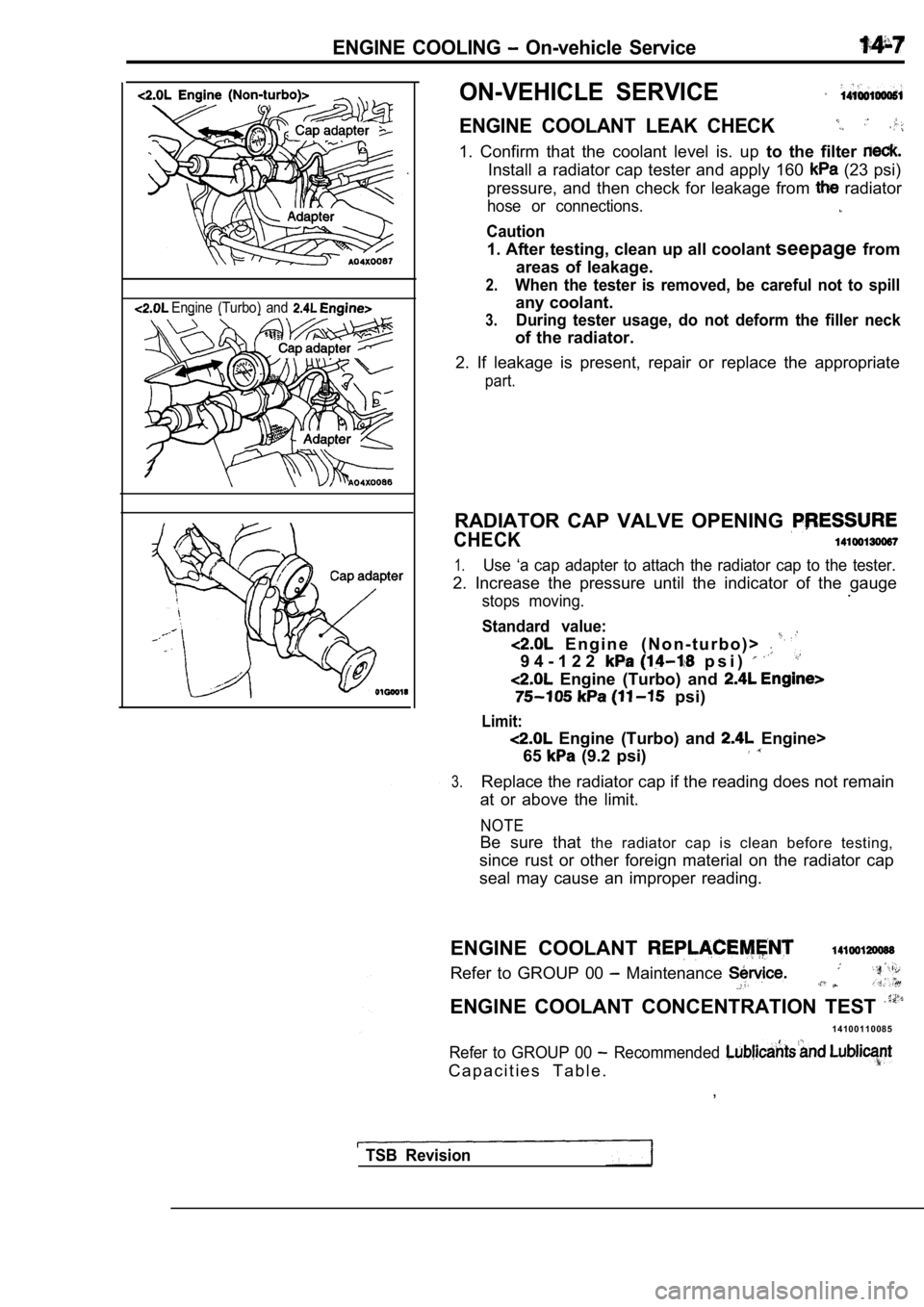
ENGINE COOLANT LEAK CHECK
1. Confirm that the coolant level is. up to the filter
Install a radiator cap tester and apply 160 (23 psi)
pressure, and then check for leakage from
radiator
hose or connections.
Caution
1. After testing, clean up all coolant seepagefrom
areas of leakage.
2.When the tester is removed, be careful not to spill
any coolant.
3.During tester usage, do not deform the filler neck
of the radiator.
2. If leakage is present, repair or replace the app ropriate
part.
RADIATOR CAP VALVE OPENING
CHECK
1.Use ‘a cap adapter to attach the radiator cap to the tester.
2. Increase the pressure until the indicator of the gauge
stops moving..
Standard value:
E n g i n e ( N o n - t u r b o ) >
9 4 - 1 2 2 p s i )
Engine (Turbo) and
psi)
Limit:
Engine (Turbo) and Engine>
65
(9.2 psi)
3.Replace the radiator cap if the reading does not re main
at or above the limit.
NOTE
Be sure that the radiator cap is clean before testing,
since rust or other foreign material on the radiato r cap
seal may cause an improper reading.
ENGINE COOLANT
Refer to GROUP 00 Maintenance
ENGINE COOLANT CONCENTRATION TEST
1 4 1 0 0 1 1 0 0 8 5
Refer to GROUP 00 Recommended
C a p a c i t i e s T a b l e . ,
TSB Revision
Page 698 of 2103
14-8ENGINE COOLING, Radiator
RADIATOR
REMOVAL AND INSTALLATION
Engine (Non-turbo)>
Operationl Engine Coolant Draining (Refer to GROUP 00 Maintenance Service.)
2
12 Nm6.7
Radiator removal steps1. Drain plug
2. Radiator cap
3. Overflow tube
4.
tank
5. Reserve tank bracket
6. upper hose 7. h o s e
8. Transaxle cooler hose, tion
10. Radiator assembly
11. Transaxle fluid cooler hose and pipe assembly
12. Lower insulator
13.Condenser fan motor assembly
14.Radiator fan motor assembly15. Fan
16. Radiator fan motor
17. Shroud
Radiator fan motor removal steps
11. Transaxle fluid cooler hose and pipe assembly
with fan motor assembly
Radiator fan motor17. Shroud
TSB Revision