Page 629 of 2103
ENGINE (TURBO)
AND
ENGINE>
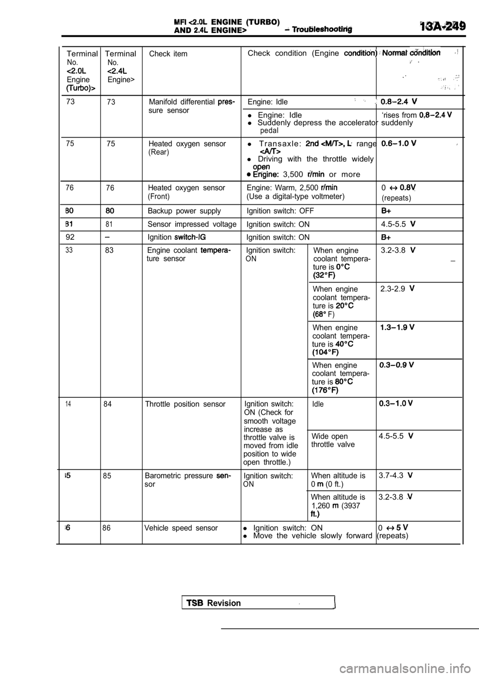
Terminal TerminalCheck itemCheck condition (Engine
No. No.
Engine Engine>
7373Manifold differential Engine: Idle
sure sensorl Engine: Idle‘rises from l Suddenly depress the accelerator suddenlypedal
75
75 Heated oxygen sensorl T r a n s a x l e : range
(Rear)l Driving with the throttle widely
3,500 or more
76
76Heated oxygen sensor Engine: Warm, 2,500 0
(Front)(Use a digital-type voltmeter)(repeats)
Backup power supply Ignition switch: OFF
81Sensor impressed voltage Ignition switch: ON4.5-5.5
92IgnitionIgnition switch: ON
3383 Engine coolant Ignition switch:When engine3.2-3.8
ture sensorONcoolant tempera-_
ture is
When engine2.3-2.9
coolant tempera-
ture is
F)
When engine
coolant tempera-
ture is
When engine
coolant tempera-
ture is
1484Throttle position sensor Ignition switch:Idle
ON (Check for
smooth voltage increase as
throttle valve is Wide open
4.5-5.5
moved from idlethrottle valve
position to wide
open throttle.)
85Barometric pressure Ignition switch: When altitude is3.7-4.3
sorON0 (0 ft.)
When altitude is
3.2-3.8
1,260 (3937
86Vehicle speed sensorl Ignition switch: ON 0l Move the vehicle slowly forward (repeats)
Revision
Page 632 of 2103
ENGINE (TURBO)
AND ENGINE> Troubleshooting
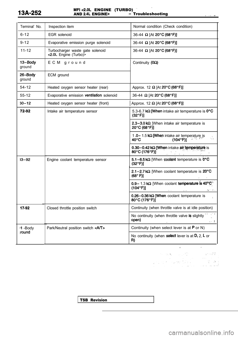
Terminal’ No.
6 - 1 2
9 - 1 2 11-12
ground
ground
54-12
55-12
72-92
17-92
-Body
Inspection item
EGR solenoid Normal condition (Check condition)
36-44 [At
Evaporative emission purge solenoid
Turbocharger waste gate solenoid
Engine (Turbo)>
36-44 [At
36-44 [At
E C M g r o u n dContinuity
ECM ground
Heated oxygen sensor heater (rear)
Evaporative emission
solenoid Approx. 12
[At
36-44 [At
Heated oxygen sensor heater (front) Approx. 12 [At
Intake air temperature sensor5.3-6.7 intake air temperature is
[When intake air temperature is
1 1.5 intake air temperature is
Engine coolant temperature sensor
intake is
.
[When temperature is
[When coolant temperature is
1.3 [When coolant
coolant temperature is
TSB Revision
Closed throttle position switch
Continuity (when throttle valve is at idle position
)
No continuity (when throttle valve
slightly
Park/Neutral position switch Continuity (when select lever is at or N)
No continuity (when lever is at 2, or
Page 638 of 2103
Analyzer
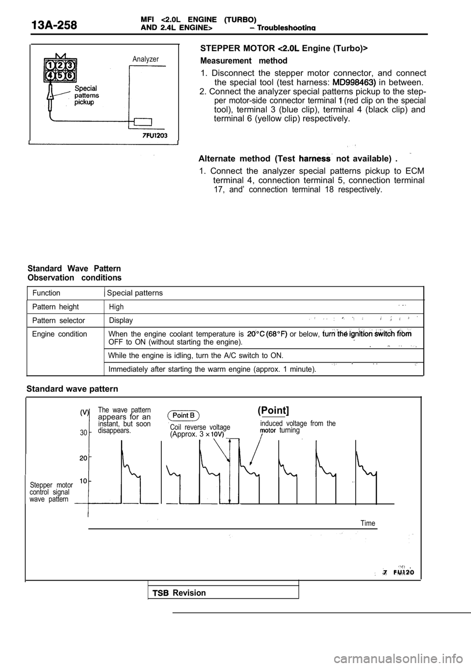
STEPPER MOTOR Engine (Turbo)>
Measurement method
1. Disconnect the stepper motor connector, and connect
the special tool (test harness:
in between.
2. Connect the analyzer special patterns pickup to the step-
per motor-side connector terminal (red clip on the special
tool), terminal 3 (blue clip), terminal 4 (black clip) and
terminal 6 (yellow clip) respectively.
Alternate method (Test
not available) .
1. Connect the analyzer special patterns pickup to ECM
terminal 4, connection terminal 5, connection termi nal
17, and’ connection terminal 18 respectively.
Standard Wave Pattern
Observation conditions
Function Special patterns
Pattern height
Pattern selector
Engine conditionHigh
Display
When the engine coolant temperature is or below,
OFF to ON (without starting the engine)..
While the engine is idling, turn the A/C switch to ON.. .Immediately after starting the warm engine (approx. 1 minute).
Standard wave pattern
The wave patternappears for aninstant, but soon
30disappears.
Stepper motor
10
control signal
wave pattern
Coil reverse voltage(Approx. 3
(Point]
induced voltage from the turning
Time
Revision
Page 642 of 2103
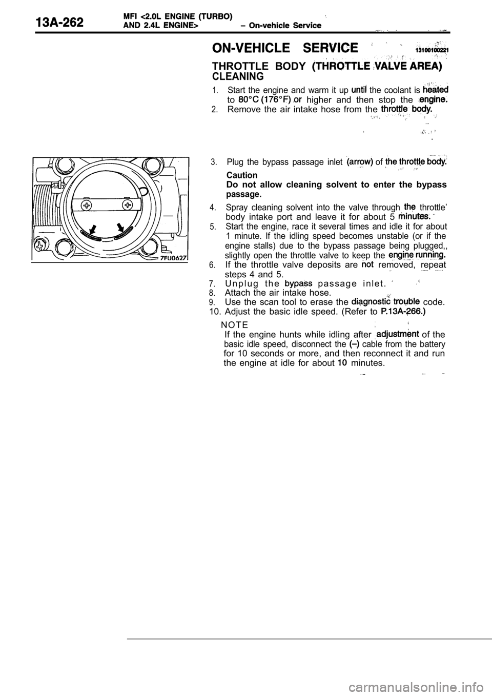
THROTTLE BODY
CLEANING
1.
2.
Start the engine and warm it up the coolant is
to higher and then stop the
Remove the air intake hose from the
.
3.
4.
5.
6.
7.
8.
9.
Plug the bypass passage inlet of
Caution
Do not allow cleaning solvent to enter the bypass
passage.
Spray cleaning solvent into the valve through throttle’
body intake port and leave it for about 5
Start the engine, race it several times and idle it for about
1 minute. If the idling speed becomes unstable (or if the
engine stalls) due to the bypass passage being plug ged,,
slightly open the throttle valve to keep the
If the throttle valve deposits are removed, repeat
steps 4 and 5.
U n p l u g t h e p a s s a g e i n l e t .
Attach the air intake hose.
Use the scan tool to erase the
code.
10. Adjust the basic idle speed. (Refer to
N O T E If the engine hunts while idling after
of the
basic idle speed, disconnect the cable from the battery
for 10 seconds or more, and then reconnect it and r un
the engine at idle for about
minutes.
Page 646 of 2103
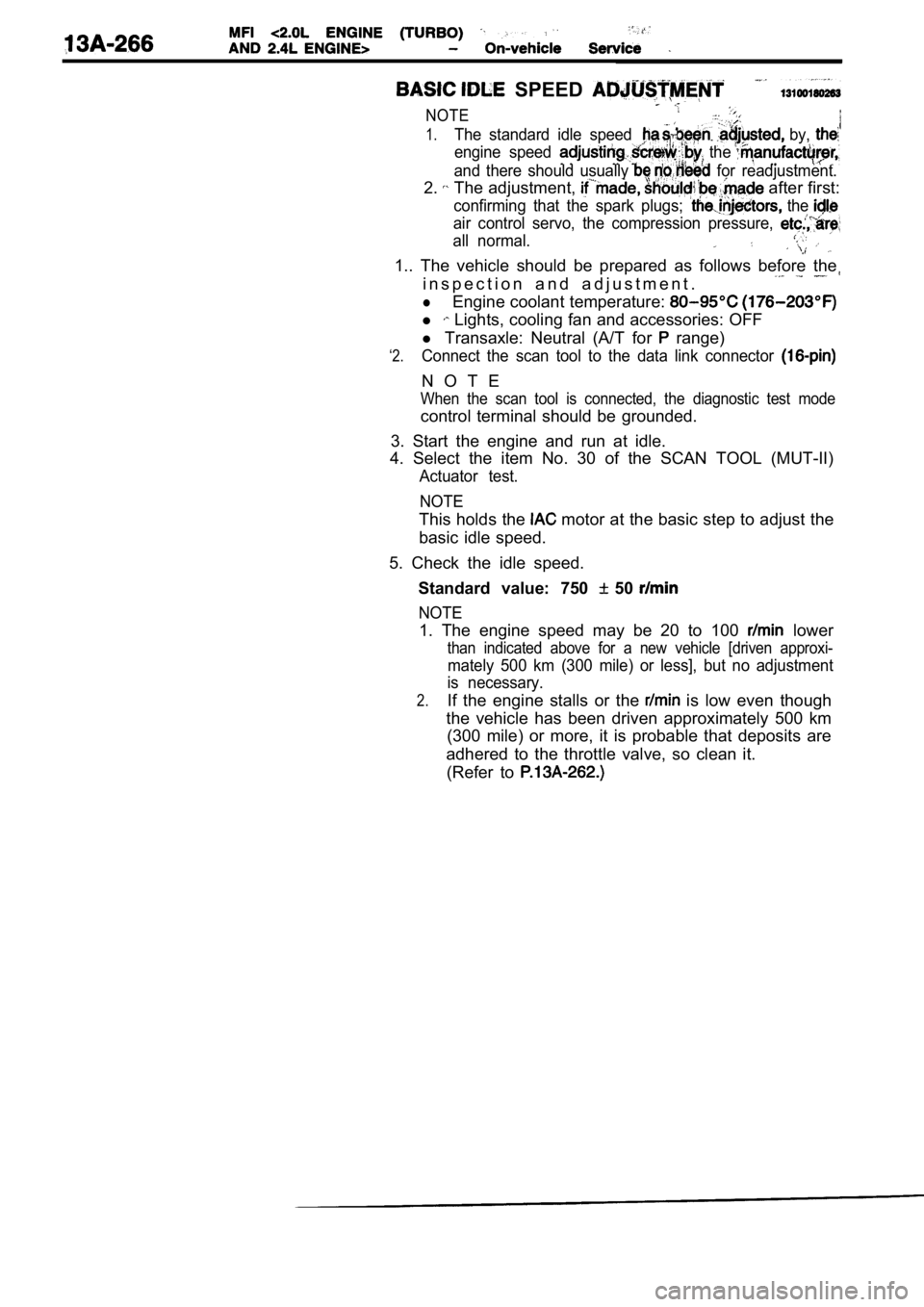
SPEED
NOTE
1.The standard idle speed by,
engine speed the
and there should usually for readjustment.
2. The adjustment, after first:
confirming that the spark plugs; the
air control servo, the compression pressure,
all normal.
1.. The vehicle should be prepared as follows before the
i n s p e c t i o n a n d a d j u s t m e n t .
lEngine coolant temperature:
l Lights, cooling fan and accessories: OFF
‘2.
l Transaxle: Neutral (A/T for range)
Connect the scan tool to the data link connector
N O T E
When the scan tool is connected, the diagnostic tes t mode
control terminal should be grounded.
3. Start the engine and run at idle.
4. Select the item No. 30 of the SCAN TOOL (MUT-II)
Actuator test.
NOTE
This holds the motor at the basic step to adjust the
basic idle speed.
5. Check the idle speed. Standard value: 750
50
NOTE
1. The engine speed may be 20 to 100 lower
than indicated above for a new vehicle [driven appr oxi-
mately 500 km (300 mile) or less], but no adjustment
is necessary.
2.If the engine stalls or the is low even though
the vehicle has been driven approximately 500 km (300 mile) or more, it is probable that deposits ar e
adhered to the throttle valve, so clean it. (Refer to
Page 652 of 2103
COMPONENT LOCATION
Engine (Turbo)>
Name
Air conditioning compressor clutch relay
Air conditioning switch Camshaft position sensor
Check engine/Malfunction indicator lamp
Crankshaft position sensor Data link connector
EGR solenoid
Engine control module (ECM)
Engine coolant temperature sensor
Evaporative emission purge solenoid
Fuel pressure solenoid
Fuel pump check terminal
Fuel pump relay
Heated oxygen sensor (Front)
Heated oxygen sensor (Rear)
Idle air control motor Ignition coil (Ignition power transistor)
NOTESymbol NameSymbol
A Injector
Knock sensor
Manifold differential pressure (MDP) sensor
fuel injection (MFI) relay
Park/Neutral position switch
Power steering pressure switch
ResistorI.
Throttle position sensor (with
throttle position switch)
Turbocharger waste gate solenoid
Vehicle speed sensor
Volume air flow sensor (with air
temperature sensor and barometric pressure
sensor)
.
The “Name” column is in alphabetical order.
Page 656 of 2103
Name
Air conditioning compressor clutch relay
Air conditioning switchSymbol Name
air control motor
coil power transistor)
Camshaft position sensor
Check engine/Malfunction indicator lamp
Crankshaft position sensor
Data link connectorIgnition power transistor
injector
Manifold differential pressure sensor
EGR solenoid fuel relavI I
Engine control module (ECM)
Engine coolant temperature sensorPark/Neutral position switch
Power steering pressure switch
Evaporative emission purge solenoid
Fuel
check terminal
Throttle position sensor (with
throttle position switch)
Fuel pump relay
Fuel pump relay module
Heated oxygen sensor (Front)
Heated oxygen sensor (Rear)Vehicle speed sensor.
Vehicle speed sensor
Volume air flow sensor (with
temperature sensor and barometric pressure
sensor)
NOTE
The “Name” column is in alphabetical order.
Page 661 of 2103
COOLANT SENSOR
Caution
Be careful not to touch the tool against the
(resin section) when and
1.Remove engine coolant temperature sensor from the in-,
take manifold.
2.With temperature sensing portion of engine tem-
perature sensor immersed in hot water, check resist ance.
,
Temperature
(32)
20 (66)
40 (104)
60 (176)
Resistance
2.1-2.7
3.If the resistance deviates from the standard value greatly,
replace the sensor.
4. Apply sealant threaded-‘portion. ,
Specified sealant:
NUT locking Part No. 4171 or equivalent,
5. Install engine coolant temperature sensor
it to specified torque.
Sensor tightening torque: 30 Nm (22
6. Fasten harness connectors securely.