1990 MITSUBISHI SPYDER coolant
[x] Cancel search: coolantPage 742 of 2103
17-2
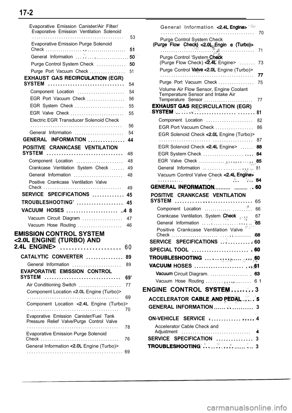
Evaporative Emission Canister/Air Filter/
Evaporative Emission Ventilation Solenoid
. . . . . . . . . . . . . . . . . . . . . . . . . . . . . . . . . . . . . . . . .53
Evaporative Emission Purge Solenoid
Check. . . . . . . . . . . . . . . . .. . . . . . . . . . . . . . . . . . .
General Information. . .. . .. . . . . . . . . . . . . . .
Purge Control System Check. . . . . . . . . . . . .
Purge Port Vacuum Check. . . . . . . . . . . . . . . .51
EXHAUST GAS (EGR)
SYSTEM. . . . . . . . . . . . . . . . . . . . . . . . . . . . . . . 54
Component Location. . . . . . . . . . . . . . . . . . . . .54
EGR Port Vacuum Check. . . . . . . . . . . . . . . . .56
EGR System Check. . . . . . . . . . . . . . . . . . . . . .55
EGR Valve Check. . . . . . . . . . . . . . . . . . . . . . . .55
Electric EGR Transducer Solenoid Check
. . . . . . . . . . . . . . . . . . . . . . . . . . . . . . . . . . . . . . . . .
56
General Information. . . . . . . . . . . . . . . . . . . . . .54
GENERAL INFORMATION. . . . . . . . . . . . . . .44
POSITIVE CRANKCASE VENTILATION
SYSTEM. . . . . . . . . . . . . . . . . . . . . . . . . . . . . . . 48
Component Location. . . . . . . . . . . . . . . . . . . . .48
Crankcase Ventilation System Check. . . . . .49
General Information. . . . . . . . . . . . . . . . . . . . . .48
Positive Crankcase Ventilation Valve
Check. . . . . . . . . . . . . . . . . . . . . . . . . . . . . . . . . . .49
SERVICE SPECIFICATIONS. . . . . . . . . . . . .45
TROUBLESHOOTING’
. . . . . . . . . . . . . . . . . . .45
VACUUM HOSES. . . . . . . . . . . . . . . . . . . . . ..4 8
Vacuum Circuit Diagram. . . . . . . . . . . . . . . . . .47
Vacuum Hose Routing
. . . . . . . . . . . . . . . . . . . .46
CONTROL SYSTEM
ENGINE (TURBO) AND
ENGINE>. . . . . . . . . . . . . . . . . . . . . 6 0
CATALYTIC CONVERTER. . . . . . . . . . . . . . .89
General Information. . . . . . . . . . . . . . . . . . . . . .89
EVAPORATIVE EMISSION CONTROL
SYSTEM. . . . . . . . . . . . . . . . . . . . . . . . . . . . . . .69’
Air Conditioning Switch
. . . . . . . . . . . . . . . . . . .77
Component Location Engine (Turbo)>
. . . . . . . . . . . . . . . . . . . . . . . . . . . . . . . . . . . . . . . . .
69
Component Location Engine (Turbo)>
. . . . . . . . . . . . . . . . . . . . . . . . . . . . . . . . . . . . . . . . .
70
Evaporative Emission Canister/Fuel Tank
Pressure Relief Valve/Purge Control Valve
. . . . . . . . . . . . . . . . . . . . . . . . . . . . . . . . . . . . . . . . .78
Evaporative Emission Purge Solenoid
Check. . . . . . . . . . . . . . . . . . . . . . . . . . . . . . . . . . .76
General Information Engine (Turbo)> G e n e r a l I n f o r m a t i o n
. . . . . . . . . . . . . . . . . .
. . . . . . . . . . . . . . . . . . . . . . .70
Purge Control System Check
. . . . . . . . . . . . . . . . . . . . . . . . . .. . . . . . . . . . . . . . . .71
Purge Control ‘System
(Purge Flow Check) Engine>. . . . . . .73
Purge Control Engine (Turbo)>
. . . . . . . . . . . . . . . . . . . . . . . . . . . . . . . . . . . . . . . . . .
Purge Port Vacuum Check. . . . . . . . . . . . . . . .75
Volume Air Flow Sensor, Engine Coolant
Temperature Sensor and Intake Air
Temperature Sensor. . . . . . . . . . . . . . . . . . . . . . .77
RECIRCULATION (EGR)
.... . .. . . . . . . . . . . . . . . . . . . . . . . .81
Component Location. . . . . . . . . . . . . . . . . . . . .82
EGR Port Vacuum Check . . . . . . . . . . . . . . . . .86
EGR Solenoid Check Engine (Turbo)>
. . . . . . . . . . . . . . . . . . . . . . . . . . . . . . . . . . . . . . . . .
87
EGR Solenoid Check Engine>. . . . . .
EGR System Check . . . . . . . . . . . . . . . . . .
EGR Valve Check. . . . . . . . . . . . .. . .
General Information... . . . . . . . . . . . . .....81
Vacuum Control Valve Check
. . . . . . . . .
.......................................
POSITIVE CRANKCASE VENTILATION
SYSTEM
. . . . . . . ... . .. . . . . . . . . . . . . . . . . 65
Component Location. . . . . . . . . . . . .. . . . . . . . .66
Crankcase Ventilation. System . .67
General Information
. . . .. . . . . ... . ........
Positive Crankcase Ventilation Valve
Check. . . . . . . . . . . . . . . . . . . . . ... . ............
SERVICE SPECIFICATIONS. .. . . . . . . . . 60
SPECIAL TOOL . . . . . . . . . . . . . . . . . . . . . . .
. . .. .
HOSES
. . . . ..
. . . . . . . . . . . . . . . . . . . . .,
Circuit Diagram.. . . . . . . . . . . . . . . . . . ,
Vacuum Hose Routing. . . . . . . ...... . . . 6 1
ENGINE CONTROL
3
ACCELERATOR
......
GENERAL INFORMATION . . . . . .. . . . . . . . . .3
ON-VEHICLE SERVICE. . . . . . . . . . . .4
Accelerator Cable Check and
Adjustment. . . . . . . . . . . . . . . . . . . . . . . . . . . . . . .
SERVICE SPECIFICATION. . . . . . . . . . . . . . .3
. ... . . . . ...3. . . . . . . . . . . . . . . . . . . . . . . . . . . . . . . . . . . . . . . . .
69
Page 790 of 2103
ENGINE AND EMISSION CONTROL
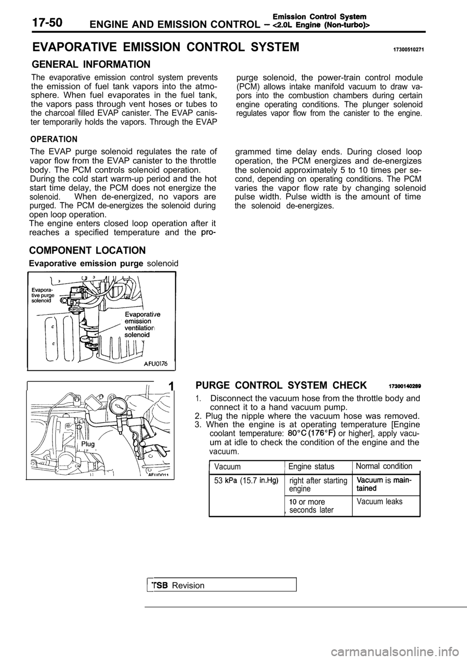
EVAPORATIVE EMISSION CONTROL SYSTEM17300510271
GENERAL INFORMATION
The evaporative emission control system prevents
the emission of fuel tank vapors into the atmo-
sphere. When fuel evaporates in the fuel tank,
the vapors pass through vent hoses or tubes to
the charcoal filled EVAP canister. The EVAP canis-
ter temporarily holds the vapors. Through the EVAP
OPERATION
The EVAP purge solenoid regulates the rate of
vapor flow from the EVAP canister to the throttle
body. The PCM controls solenoid operation.
During the cold start warm-up period and the hot
start time delay, the PCM does not energize the
solenoid.When de-energized, no vapors are
purged. The PCM de-energizes the solenoid during
open loop operation.
The engine enters closed loop operation after it
reaches a specified temperature and the
COMPONENT LOCATION
Evaporative emission purge solenoidpurge solenoid, the power-train control module
(PCM) allows intake manifold vacuum to draw va-
pors into the combustion chambers during certain
engine operating conditions. The plunger solenoid
regulates vapor flow from the canister to the engin e.
grammed time delay ends. During closed loop
operation, the PCM energizes and de-energizes
the solenoid approximately 5 to 10 times per se-
cond, depending on operating conditions. The PCM
varies the vapor flow rate by changing solenoid
pulse width. Pulse width is the amount of time
the solenoid de-energizes.
Revision
I 1PURGE CONTROL SYSTEM CHECK
1.Disconnect the vacuum hose from the throttle body a nd
connect it to a hand vacuum pump.
2. Plug the nipple where the vacuum hose was remove d.
3. When the engine is at operating temperature [Eng ine
coolant temperature: or higher], apply vacu-
um at idle to check the condition of the engine and the
vacuum.
Vacuum Engine status Normal condition
53
(15.7 right after starting
engine is
or moreVacuum leaks
, seconds later
Page 792 of 2103

ENGINE AND EMISSION CONTROL
ENGINE COOLANT TEMPERATURE SENSOR
AND INTAKE AIR TEMPERATURE SENSOR
To check these parts, refer to GROUP Troubleshooting.
AIR CONDITIONING SWITCH17300200031
To check the air conditioning switch, refer to GROU P 55
Air Conditioning Switch.
TSB Revision
Page 795 of 2103
Emission Control
Engine
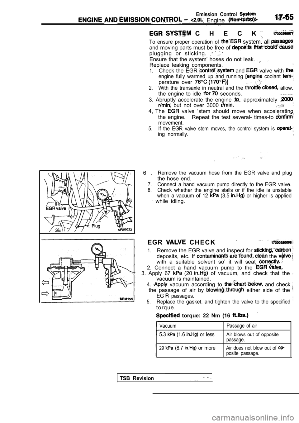
C H E C K . .
To ensure proper operation of system, all
and moving parts must be free of
plugging or sticking.
Ensure that the system’ hoses do not leak.
Replace leaking components.
1.Check the EGR and valve with
engine fully warmed up and running coolant
perature over
2.With the transaxle in neutral and the allow.
the engine to idle seconds.
3. Abruptly accelerate the engine
approximately
but not over 3000
4, The valve ‘stem should move when accelerating
the engine. Repeat the test several- times-to
movement.
5.If the EGR valve stem moves, the control system is
ing normally.
6 .Remove the vacuum hose from the EGR valve and plug
the hose end.
7.Connect a hand vacuum pump directly to the EGR valv e.
8.Check whether the engine stalls or if the idle is unstable
when a vacuum of 12
(3.5 or higher is applied
while idling.
E G R
C H E C K
1.Remove the EGR valve and inspect for
deposits, etc. If the
with a suitable solvent so’ it will seat
2. Connect a hand vacuum pump to the
3. Apply 67 (20 of vacuum, and check that the
vacuum is maintained.
4.
vacuum according to and check
the passage of air by either side of the
EG passages.
5.Replace the gasket, and tighten the valve to the sp ecified
t o r q u e .
torque: 22 Nm (16
Vacuum
5.3 (1.6 or less
Passage of air
Air blows out of opposite
passage.
29 (8.7 or moreAir does not blow out of
posite passage.
TSB Revision
Page 808 of 2103
17-68ENGINEAND EMISSION CONTROL (Turbo) and
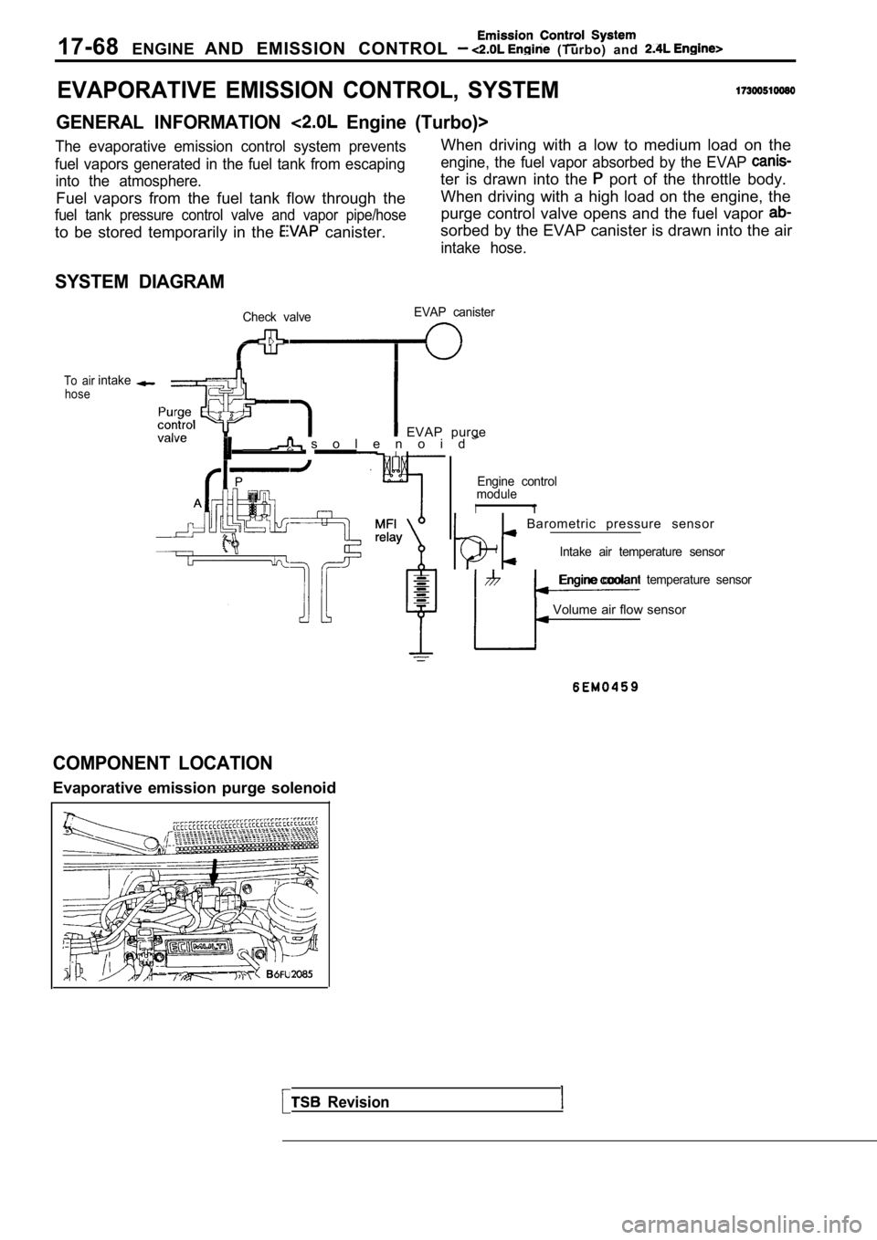
EVAPORATIVE EMISSION CONTROL, SYSTEM
GENERAL INFORMATION Engine (Turbo)>
The evaporative emission control system preventsWhen driving with a low to medium load on the
fuel vapors generated in the fuel tank from escapin gengine, the fuel vapor absorbed by the EVAP
into the atmosphere.ter is drawn into the port of the throttle body.
Fuel vapors from the fuel tank flow through the When driving with a high load on the engine, the
fuel tank pressure control valve and vapor pipe/hos
epurge control valve opens and the fuel vapor
to be stored temporarily in the canister.sorbed by the EVAP canister is drawn into the air
intake hose.
SYSTEM DIAGRAM
Check valve EVAP canister
To air
hoseintake
EVAP purge s o l e n o i d
Revision
Engine control
module
I1
Barometric pressure sensor
Intake air temperature sensor
Engine coolant temperature sensor
Volume air flow sensor
COMPONENT LOCATION
Evaporative emission purge solenoid
Page 809 of 2103
(Turbo) and
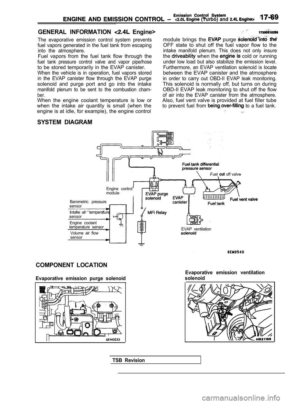
GENERAL INFORMATION Engine>
The evaporative emission control system prevents
fuel vapors generated in the fuel tank from escapin g
into the atmosphere.
Fuel vapors from the fuel tank flow through the
fuel tank pressure control valve and vapor pipe/hos e
to be stored temporarily in the EVAP canister.
When the vehicle is in operation, fuel vapors stored
in the EVAP canister flow through the EVAP purge
solenoid and purge port and go into the intake
manifold plenum to be sent to the combustion cham-
ber.
When the engine coolant temperature is low or
when the intake air quantity is small (when the
module brings the purge
OFF state to shut off the fuel vapor flow to the
intake manifold plenum. This does not only insure
the when the cold or running
under low load but also stabilize the emission leve l.
Furthermore, an EVAP ventilation solenoid is locate
between the EVAP canister and the atmosphere
in order to carry out OBD-II EVAP leak monitoring.
This solenoid is normally off, but turns on during
OBD-II EVAP leak monitoring to shut off the flow
of air into the EVAP canister from the atmosphere.
Also, fuel vent valve is provided at fuel filler tu be
to prevent fuel from to a fuel tank.
engine is at idle, for example), the engine control
SYSTEM DIAGRAM
Fuel off valve
Engine control
module
Barometric pressure
sensor
Intake air temperature
sensor
Engine coolant
temperature sensor
Volume air flow
sensorEVAP ventilation
COMPONENT LOCATION
Evaporative emission purge solenoid
Evaporative emission ventilation
solenoid
TSB Revision
Page 810 of 2103
17-70 CONTROL (Turbo) and Engine>
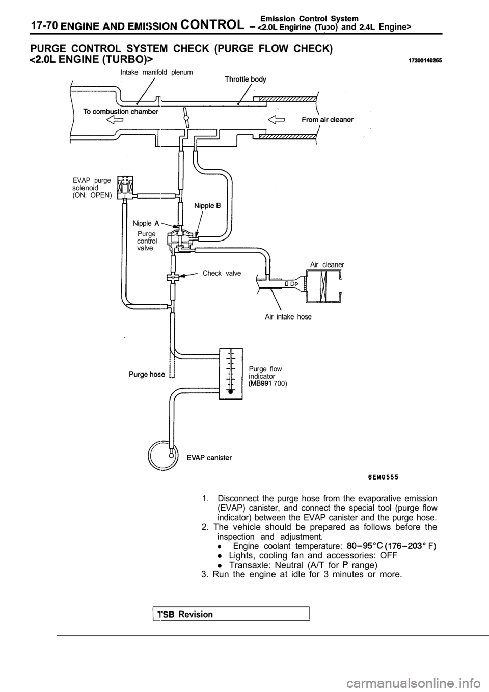
PURGE CONTROL SYSTEM CHECK (PURGE FLOW CHECK)
ENGINE (TURBO)>
Intake manifold plenum
EVAP purgesolenoid(ON: OPEN)
Nipple
Purgecontrolvalve
Check valve Air cleaner
Air intake hose
Purge flow
indicator
700)
1.Disconnect the purge hose from the evaporative emis sion
(EVAP) canister, and connect the special tool (purg e flow
indicator) between the EVAP canister and the purge hose.
2. The vehicle should be prepared as follows before the
inspection and adjustment.
lEngine coolant temperature: F)
l Lights, cooling fan and accessories: OFF
l Transaxle: Neutral (A/T for
range)
3. Run the engine at idle for 3 minutes or more.
Revision
Page 812 of 2103
(Turbo) and Engine>
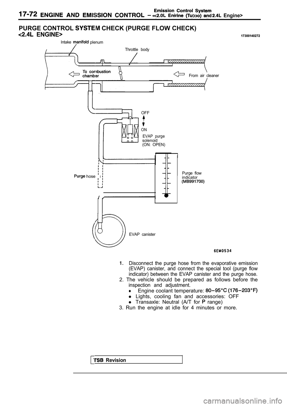
PURGE CONTROL CHECK (PURGE FLOW CHECK)
ENGINE>17300140272
IntakeplenumThrottle body
From air cleaner
OFF
ON EVAP purge
solenoid
(ON: OPEN)
hose IPurge flow
indicator
Revision
EVAP canister
Disconnect the purge hose from the evaporative emis sion
(EVAP) canister, and connect the special tool (purg e flow
indicator) between the EVAP canister and the purge hose.
2. The vehicle should be prepared as follows before the
inspection and adjustment.
lEngine coolant temperature:
l Lights, cooling fan and accessories: OFF
l Transaxle: Neutral (A/T for
range)
3. Run the engine at idle for 4 minutes or more.