1989 MITSUBISHI GALANT wiring
[x] Cancel search: wiringPage 964 of 1273
ACTIVE-ELECTRONIC CONTROL SUSPENSION - Troubleshooting 33B-25
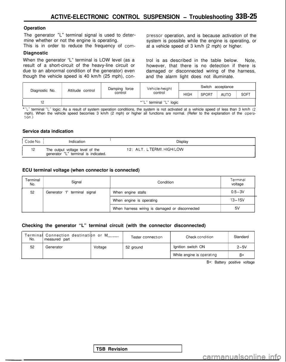
OperationThe generator
‘I-” terminal signal is used to deter-
pressor
operation, and is because activation of the
mine whether or not the engine is operating.
This is in order to reduce the frequency of
com-
system is possible while the engine is operating, or
at a vehicle speed of 3 km/h (2 mph) or higher.
Diagnostic
When the generator “L” terminal is LOW level (as a result of a short-circuit of the heavy-line circuit or
due to an abnormal condition of the generator) even
though the vehicle speed is 40 km/h (25 mph),
con-
trol is as described in the table below.Note,
however, that there is no detection if there is
damaged or disconnected wiring of the harness,
and the alarm light does not illuminate.
Diagnostic No. Attitude control Damping force
control Vehrcle-height
control
HIGH
Switch acceptance
SPORTAUTOSOFT
I12‘“L” terminal “L” logic
““L” terminal “L” logic: As a result of system operation conditions, the system is not ac\
tivated at a vehicle speed of less than 3 km/h (2mph). When the vehicle speed becomes 3 km/h (2 mph) or higher all fun\
ctions are normal. (Refer to the explanation of the opera-
tron.)
Service data indication
1 CodeNo. /Indication Display
I12The output voltage level of the12: ALT. LTERMI.
HIGH/LOW
generator “L” terminal is indicated.
TSB Revision
ECU terminal voltage (when connector is connected)
Terminal
No.Signal Condition Termrnal
voltage
52Generator ‘I” terminal signal When engine stalls
When engine is operating
When harness wiring is damaged or disconnected0.5-3v
13-15v
5v
Checking the generator “L” terminal circuit (with the connector d\
isconnected)
Terminal Connection destination or
M
easurement
No.measured part Tester connectronCheck condrtion
Standard
52 Generator
Voltage52 ground Ignition switch ON
2-5V
While engine is operatingB+
B+: Battery positive voltage
Page 966 of 1273
ACTIVE-ELECTRONIC CONTROL SUSPENSION - Troubleshooting 33B-27
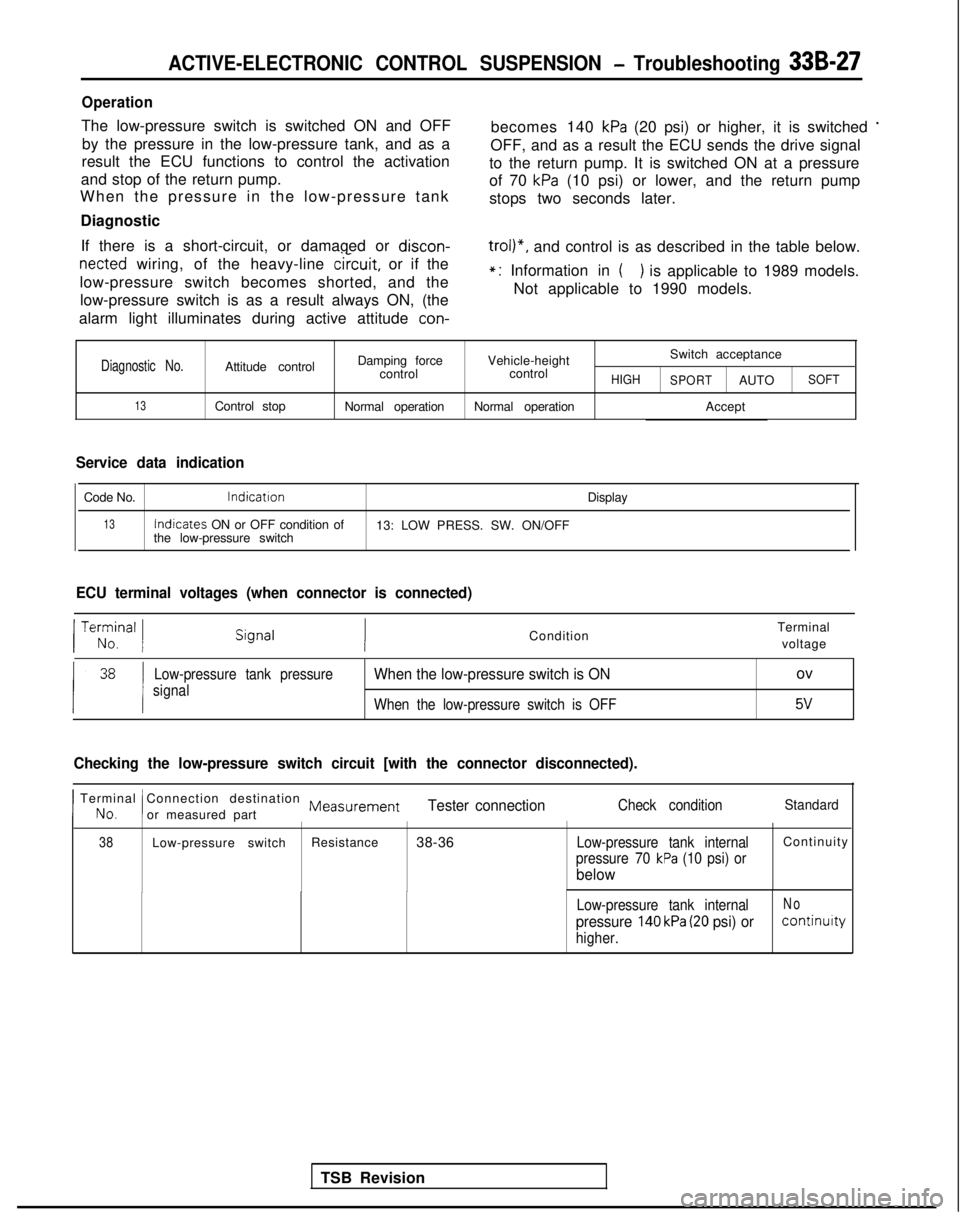
Operation
The low-pressure switch is switched ON and OFFby the pressure in the low-pressure tank, and as a becomes 140 kPa (20 psi) or higher, it is switched *
result the ECU functions to control the activation
OFF, and as a result the ECU sends the drive signal
and stop of the return pump. to the return pump. It is switched ON at a pressure
When the pressure in the low-pressure tank of 70
kPa (10 psi) or lower, and the return pump
stops two seconds later.
Diagnostic
If there is a short-circuit, or damaged or discon-
netted wiring, of the heavy-line
circuit,
or if the
low-pressure switch becomes shorted, and the low-pressure switch is as a result always ON, (the
trol)“, and control is as described in the table below.
alarm light illuminates during active attitude
con-
*: Information in () is applicable to 1989 models.
Not applicable to 1990 models.
Diagnostic No.Attitude control Damping force
Vehicle-height Switch acceptance
control controlHIGH
SPORTAUTOSOFT
13Control stop Normal operationNormal operation Accept
Service data indication
Code No.lndicatron
Display
13Indicates
ON or OFF condition of
13: LOW PRESS. SW. ON/OFF
the low-pressure switch
ECU terminal voltages (when connector is connected)
TSB Revision
/ Te;;,nal 1Condition Terminal
voltage
Low-pressure tank pressure
signalWhen the low-pressure switch is ONov
When the low-pressure switch is OFF5v
Checking the low-pressure switch circuit [with the connector disconnecte\
d).
I No.
Terminal Connection destination Measurement
!or measured partTester connectionCheck conditionStandard
38Low-pressure switch Resistance
38-36Low-pressure tank internalContinuit
y
pressure 70 kPa (10 psi) or
below
Low-pressure tank internalNo
pressure 140 kPa (20 psi) orcontinuity
higher.
Page 968 of 1273
ACTIVE-ELECTRONIC CONTROL SUSPENSION - Troubleshooting 33B-29
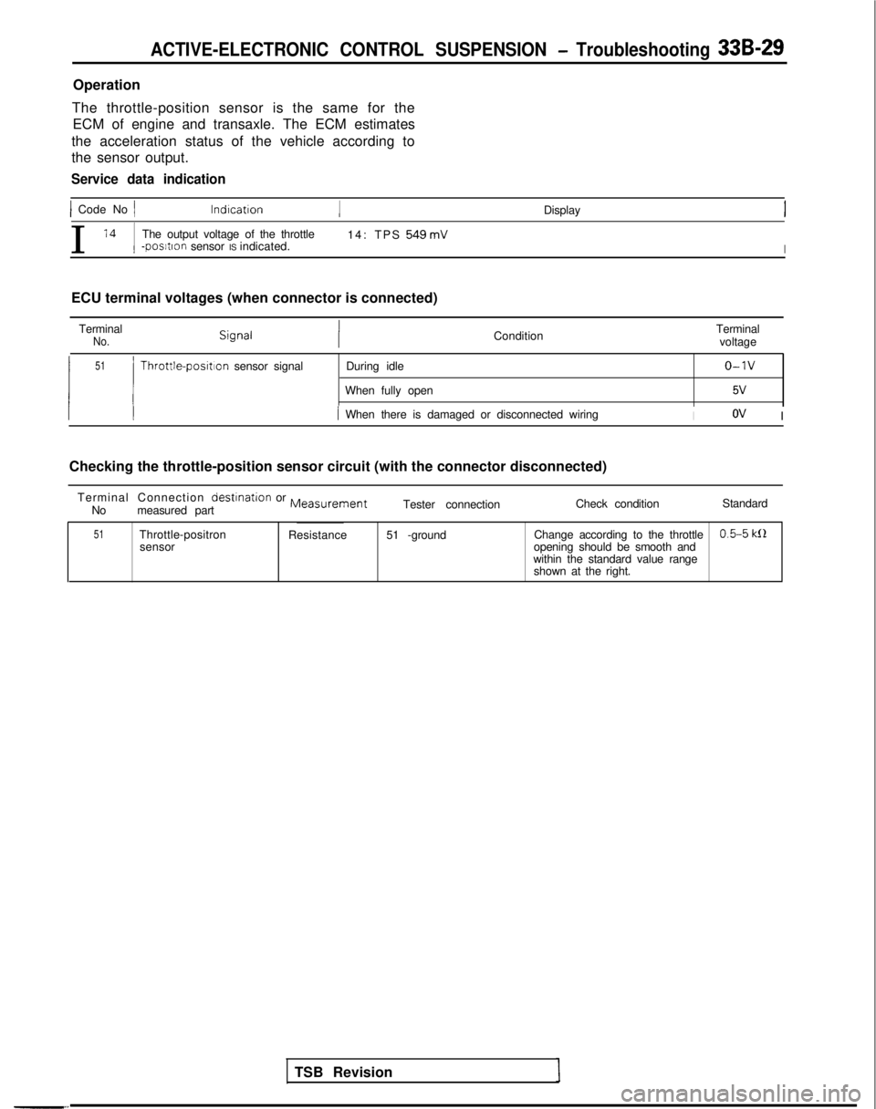
Operation
The throttle-position sensor is the same for the ECM of engine and transaxle. The ECM estimates
the acceleration status of the vehicle according to
the sensor output.
Service data indication
) Code No 1 lndrcatron
Display
I
l4 1
The output voltage of the throttle 14: TPS 549mV-postron sensor IS indicated.I
ECU terminal voltages (when connector is connected)
Terminal
No.Condition Terminal
voltage
51
1 !
Throttle-posrtlon sensor signal During idleo-1v
When fully open5v
/ When there is damaged or disconnected wiringIov I
Checking the throttle-position sensor circuit (with the connector disco\
nnected) Terminal Connection
destrnation or MeasurementNo measured part Tester connection
Check condition
Standard
51Throttle-positron
sensor Resistance
51 -ground Change according to the throttle0.5-5 k0opening should be smooth and
within the standard value range shown at the right.
TSB Revision
Page 970 of 1273
ACTIVE-ELECTRONIC CONTROL SUSPENSION - Troubleshooting 33B-31
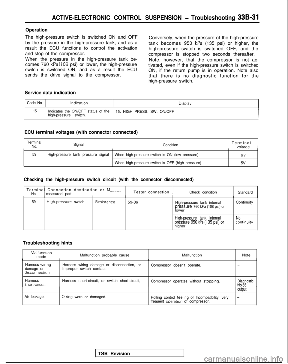
Operation
The high-pressure switch is switched ON and OFF by the pressure in the high-pressure tank, and as a
result the ECU functions to control the activation
and stop of the compressor.
When the pressure in the high-pressure tank be-
comes 760
kPa (108 psi) or lower, the high-pressure
switch is switched ON, and as a result the ECU
sends the drive signal to the compressor. Conversely, when the pressure of the high-pressure
tank becomes 950
kPa (135 psi) or higher, the
high-pressure switch is switched OFF, and the
compressor is stopped two seconds thereafter.
Note, however, that the compressor is not ac-
tivated, even if the high-pressure switch is switched ON, if the return pump is in operation. Note also
that there is no diagnostic function for the
high-pressure switch.
Service data indication Code No
lndlcationDisDlav
15Indicates the ON/OFF status of the
high-pressure switch. 15: HIGH PRESS. SW. ON/OFF
I
ECU terminal voltages (with connector connected)
Terminal
No.Signal ConditionTermina
l
voltaaeI
59
High-pressure tank pressure signal
When high-pressure switch is ON (low pressure)
o
v
When high-pressure switch is OFF (high pressure)
5v
Checking the high-pressure switch circuit (with the connector disconnec\
ted)
Terminal Connection destination or
M
easurement
Nomeasured part Tester connection ,
Check conditionStandard
59High-pressure
switch Reststance
59-36
High-pressure tank internal
pressure 760 kPa (108 psi) orlower Continuity
High-pressure tank internalpressure 950 kPa (135 psi) orhigher
Nocontinurty
Troubleshooting hints
Malfunctlonmode
Malfunction probable cause
MalfunctionNote
TSB Revision
Harness
wlrlngdamage ordlsconnectlon
Harness wiring damage or disconnection, or
Improper switch contact Compressor doesn’t operate.-
Harnessshort-crrcuit
Air leakage. Harness short-circuit, or switch short-circuit, O-ring
worn or damaged. Compressor operates without stopplng.DiagnosticNo.55output.
Rolling control feehng
of Incompatibility. very-freauent oaeration of compressor.
Page 974 of 1273
ACTIVE-ELECTRONIC CONTROL SUSPENSION - Troubleshooting 33B-35
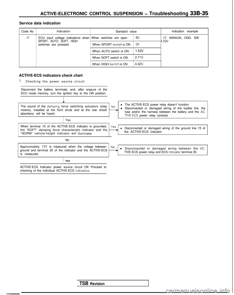
Service data indication
Code No Indication
Standard value
17ECU input voltage indications when When switches are openSPORT, AUTO, SOFT, HIGH5V
switches are pressed.When SPORT switch
is ONOV
When AUTO switch is ON1.53v
When SOFT switch is ON 2.71V
When HIGH swrtch
is ON 4.02V
ACTIVE-ECS indicators check chart
1.Checking the power source circuit
Disconnect the battery terminals, and, after erasure of the
ECU mode memory, turn the ignition key to the ON position.
1
Indication example
17: MANUAL CNG. SW
4.03v
The sound of the damplng force switching actuators (steplNoThe ACTIVE-ECS power relay doesn’t function
motors), installed at the front struts and at the rear shock
--+l Disconnected or damaged wiring of the fusible link, the
absorbers, will be heard. fuse and/or the harness between the battery and the AC-TIVE-ECS power relay contacts
Yes
When terminal 15 of the ACTIVE-ECS indicator is grounded,yes
the “SOFT” damping force characteristic indicator and the -lDisconnected or damaged wiring of the ground line 15 of
“NORM” vehicle-height indicator will
illuminate.the ACTIVE-ECS indicator.
No
Approximately
12V is measured when the voltage betweenNo
ground and terminal 20 of the indicator and the ACTIVE-ECS --+l Disconnected or damaged wiring between the AC-
is measured. TIVE-ECS power relay and ECS Indicator
terminal 20.
I Yes
TSB Revision
-. ACTIVE-ECS Indicator power source circuit OK Proceed to
checking of the individual ACTIVE-ECS
lndlcators
Page 975 of 1273
33B-36 ACTIVE-ELECTRONIC CONTROL SUSPENSION - Troubleshooting
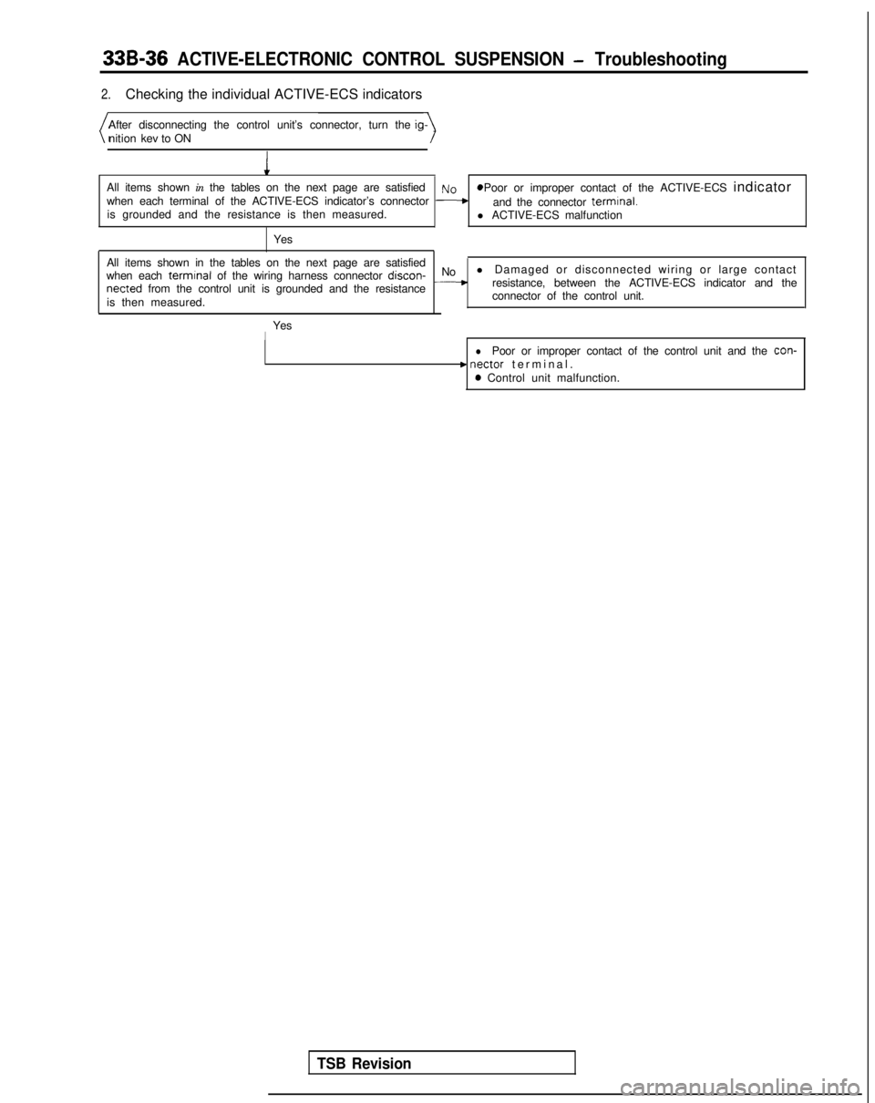
2.Checking the individual ACTIVE-ECS indicators
After disconnecting the control unit’s connector, turn the nition kev to ON
1
All items shown in the tables on the next page are satisfied~~ 8 Poor or improper contact of the ACTIVE-ECS indicator
when each terminal of the ACTIVE-ECS indicator’s connector Fand the connector terminal.is grounded and the resistance is then measured. l ACTIVE-ECS malfunction
Yes
All items shown in the tables on the next page are satisfied
when each
terminal of the wiring harness connector discon-
No
l Damaged or disconnected wiring or large contactnetted from the control unit is grounded and the resistance__*resistance, between the ACTIVE-ECS indicator and the
is then measured. connector of the control unit.
Yes
I
lPoor or improper contact of the control unit and the con-
c nectar terminal
.
0 Control unit malfunction.
TSB Revision
Page 976 of 1273
ACTIVE-ELECTRONIC CONTROL SUSPENSION - Troubleshooting 33B-37
r
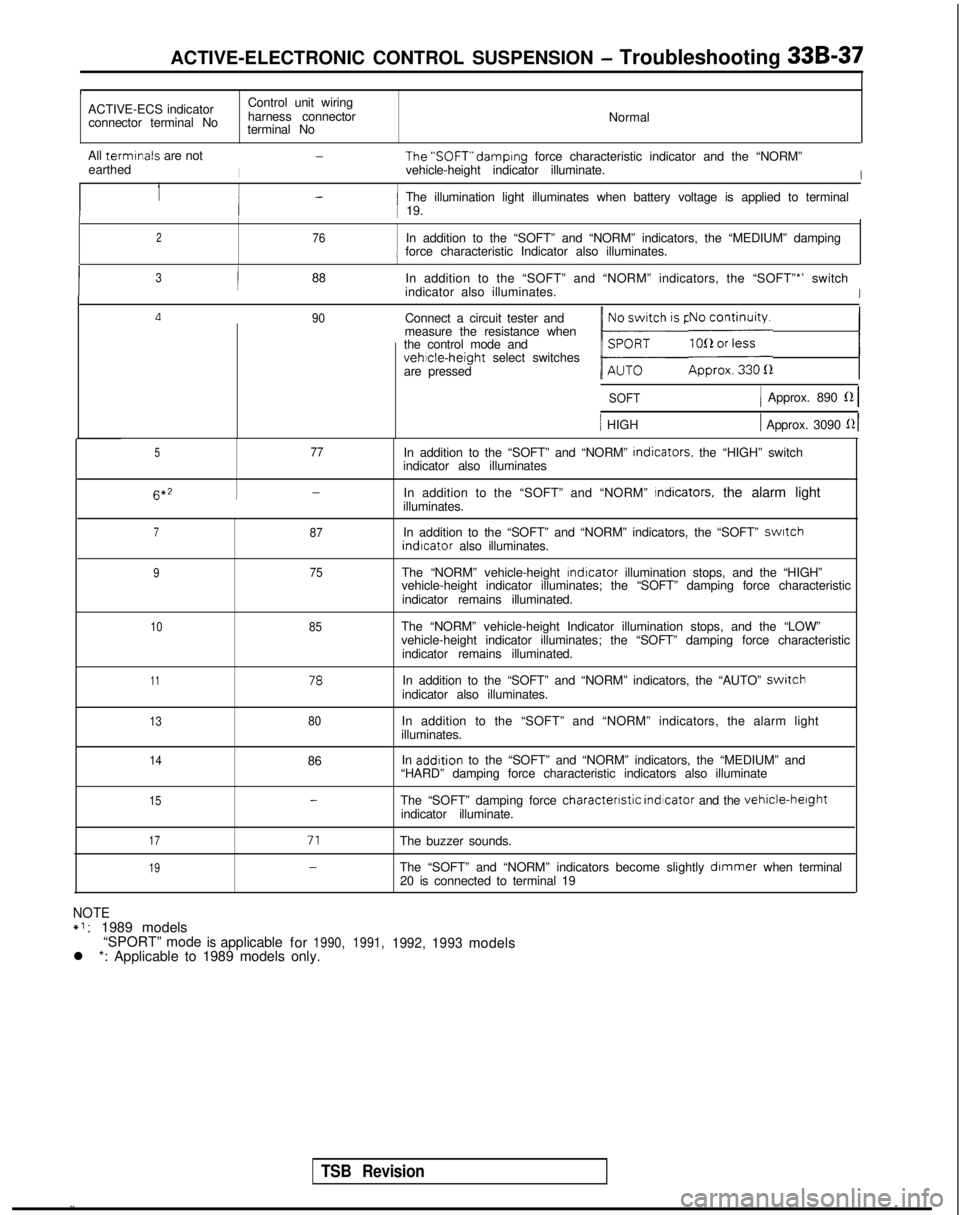
ACTIVE-ECS indicator
Control unit wiring
connector terminal No harness connector
Normal
terminal No
All termrnals
are not
I
-The’SOFT” damprng
force characteristic indicator and the “NORM”
earthed vehicle-height indicator illuminate.
I
1-1 The illumination light illuminates when battery voltage is applied to t\
erminali 19.
276In addition to the “SOFT” and “NORM” indicators, the “MED\
IUM” dampingi force characteristic Indicator also illuminates.
I3/88
In addition to the “SOFT” and “NORM” indicators, the “SOF\
T”*’ switch
indicator also illuminates.
I
Ll90Connect a circuit tester and
measure the resistance when
the control mode and
vehicle-height select switches
are pressed
1 b;h is pressed.1 E;i;yi;;a 1
SOFT1 Approx. 890 fZ 1
/ HIGH1 Approx. 3090 121
577In addition to the “SOFT” and “NORM”
Indicators.
the “HIGH” switch
indicator also illuminates 6*2
-In addition to the “SOFT” and “NORM” Indicators, the alarm light
illuminates.
787In addition to the “SOFT” and “NORM” indicators, the “SOF\
T” swatch indrcator
also illuminates.
975The “NORM” vehicle-height rndicator
illumination stops, and the “HIGH”
vehicle-height indicator illuminates; the “SOFT” damping force cha\
racteristic
indicator remains illuminated.
1085The “NORM” vehicle-height Indicator illumination stops, and the “\
LOW”
vehicle-height indicator illuminates; the “SOFT” damping force cha\
racteristic indicator remains illuminated.
1178In addition to the “SOFT” and “NORM” indicators, the “AUT\
O” switchindicator also illuminates.
1380In addition to the “SOFT” and “NORM” indicators, the alarm l\
ight
illuminates.
1486 In addrtion
to the “SOFT” and “NORM” indicators, the “MEDIUM” and\
“HARD” damping force characteristic indicators also illuminate
15-The “SOFT” damping force characterrstic
indicator and the vehicle-herghtindicator illuminate.
17
1971
-
The buzzer sounds.
The “SOFT” and “NORM” indicators become slightly
dimmer when terminal
20 is connected to terminal 19
NOTE*l:1989 models
“SPORT” modeisapplicable for1990, 1991,1992,1993models
l *: Applicable to 1989 models only.
TSB Revision
Page 978 of 1273
ACTIVE-ELECTRONIC CONTROL SUSPENSION - Troubleshooting 33B-39
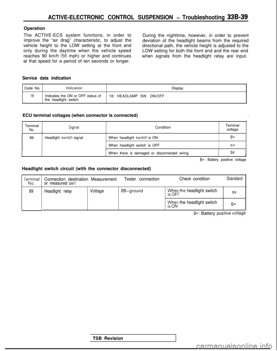
Operation
The ACTIVE-ECS system functions, in order to improve the “air drag” characteristic, to adjust the During the nighttime, however, in order to prevent
vehicle height to the LOW setting at the front end deviation of the headlight beams from the required
only during the daytime when the vehicle speed directional path, the vehicle height is adjusted to the
reaches 90 km/h
(56 mph) or higher and continues LOW setting for both the front end and the rear end
at that speed for a period of ten seconds or longer. when signals from the headlight relay are input.
Service data indication
Code No.lndlcation
Display
18Indicates the ON or OFF status of
18: HEADLAMP SW. ON/OFF
the headlight switch.
ECU terminal voltages (when connector is connected)
/
TerminalNo. Slgnal
ConditionTerminal
voltage
89 Headlight switch
signal When headlight
switch is ON
When headlight switch is OFFB+
o
v
When there is damaged or disconnected wiring
5vJ
B+: Battery positive voltage
Headlight switch circuit (with the connector disconnected)
TSB Revision
TeKJna’
89
Connection destination Measurement Tester connectionCheck conditionStandard
or measured Dart
Headlight relayVoltage 89-groundph&the headlight switchov
rt$z; the headlight switchB+
~.A.-II___B+: Battery posrrrve voltage