1989 MITSUBISHI GALANT wiring
[x] Cancel search: wiringPage 479 of 1273
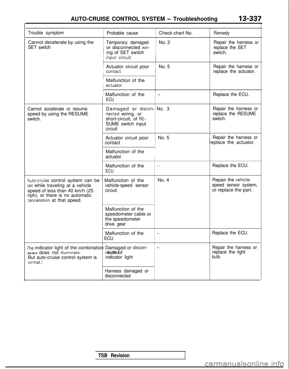
AUTO-CRUISE CONTROL SYSTEM - Troubleshooting
13-337
Trouble symptom
Cannot decelerate by using the
SET switch
Probable cause
Check chart No.Remedy
Temporary damagedNo. 2Repair the harness or
or disconnected wir-
replace the SET
ing of SET switchswitch.
Actuator circuit poorNo. 5Repair the harness or
replace the actuator.
Malfunction of the
1 Malfunction of the
ECU
-Replace the ECU.
Cannot accelerate or resume
speed by using the RESUME
switch.
Damaged or discon- No. 3 netted
wiring, or
short-circuit, of
RE-
SUME switch input
circuit Repair the harness or
replace the RESUME
switch.
Actuator circuit poor No. 5iRepair the harness or
; contact replace the actuator.
Malfunction of the
actuator
,
Malfunction of the-Replace the ECU.
ECU
Jute-cruise control system can be i Malfunction of the No. 4
Repair the vehicle-
set while traveling at a vehiclevehicle-speed sensor speed sensor system,
speed of less than 40 km/h (25circuitor replace the part.
nph), or there is no automatic
zancellation at that speed.
Malfunction of the
speedometer cable or
the speedometer
drive gear
Malfunction of the
’ ECU
-Replace the ECU.
The indicator light of the combination Damaged or discon-
neter does not illuminate. netted bulb of
But auto-cruise control system isindicator light
lormal.1
-Repair the harness or
replace the light
bulb.
Harness damaged or
disconnected
TSB Revision
Page 493 of 1273
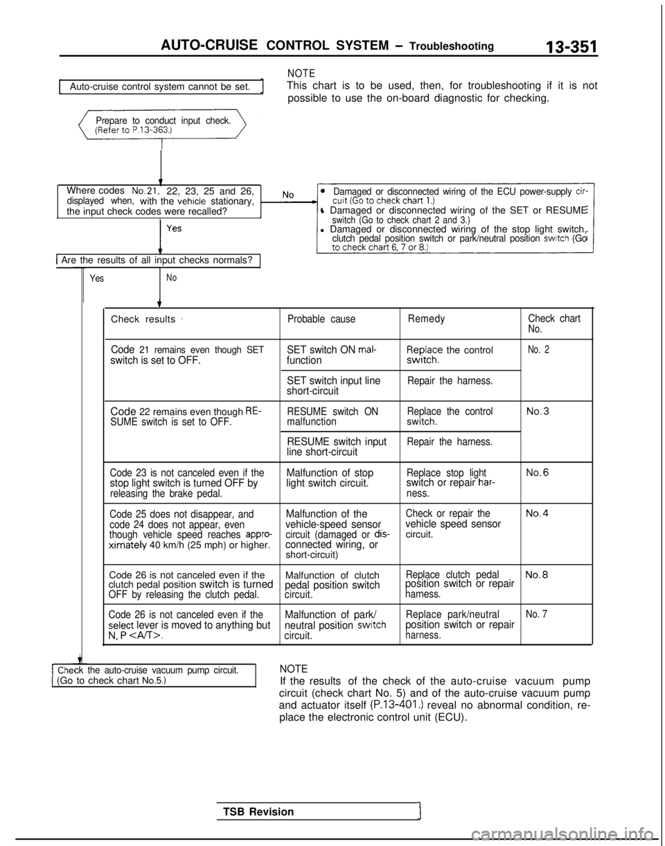
AUTO-CRUISE CONTROL SYSTEM - Troubleshooting
NOTE
13-351
Auto-cruise control system cannot be set.
This chart is to be used, then, for troubleshooting if it is not
possible to use the on-board diagnostic for checking.
Prepare to conduct input check.
Where codesNo.21,22, 23, 25 and 26,displayed when,with the vehicle stationary,
the input check codes were recalled?Damaged or disconnected wiring of the ECU power-supply cir-
l Damaged or disconnected wiring of the SET or RESUMEswitch (Go to check chart 2 and 3.)l Damaged or disconnected wiring of the stop light switch,clutch pedal position switch or park/neutral position switch (Go
1 Are the results of all input checks normals?
YesNo
ck the auto-cruise vacuum pump circuit.1 (Go to check chart No.5.)
TSB Revision1 7
Check results
’Probable cause RemedyCheck chartNo.
Code 21 remains even though SETswitch is set to OFF. SET switch ON mal-function
SET switch input line
short-circuitF,I~JI;? the control
Repair the harness.
No. 2
Code 22 remains even though RE-SUME switch is set to OFF. RESUME switch ON
Replace the controlNo.3malfunctionswitch.
RESUME switch inputRepair the harness.line short-circuit
Code 23 is not canceled even if theMalfunction of stopReplace stop lightNo.6
stop light switch is turned OFF by light switch circuit.switch or repair har-
releasing the brake pedal.
ness.
Code 25 does not disappear, and
Malfunction of theCheck or repair theNo.4
code 24 does not appear, evenvehicle-speed sensor vehicle speed sensorthough vehicle speed reaches appro-circuit (damaged or dis-circuit.ximately 40 km/h (25 mph) or higher.connected wiring, orshort-circuit)
Code 26 is not canceled even if the Malfunction of clutch
Replace clutch pedalNo.8clutch pedal position switch is turnedpedal position switchposition switch or repairOFF by releasing the clutch pedal.
circuit.harness.
Code 26 is not canceled even if the
Malfunction of park/Replace park/neutralNo. 7
select lever is moved to anything but neutral position ,switchposition switch or repair
v. P .circuit.harness.
NOTE
If the results of the check of the auto-cruise vacuum pump
circuit (check chart No. 5) and of the auto-cruise vacuum pump
and actuator itself
(P.13-401.) reveal no abnormal condition, re-
place the electronic control unit (ECU).
Page 494 of 1273
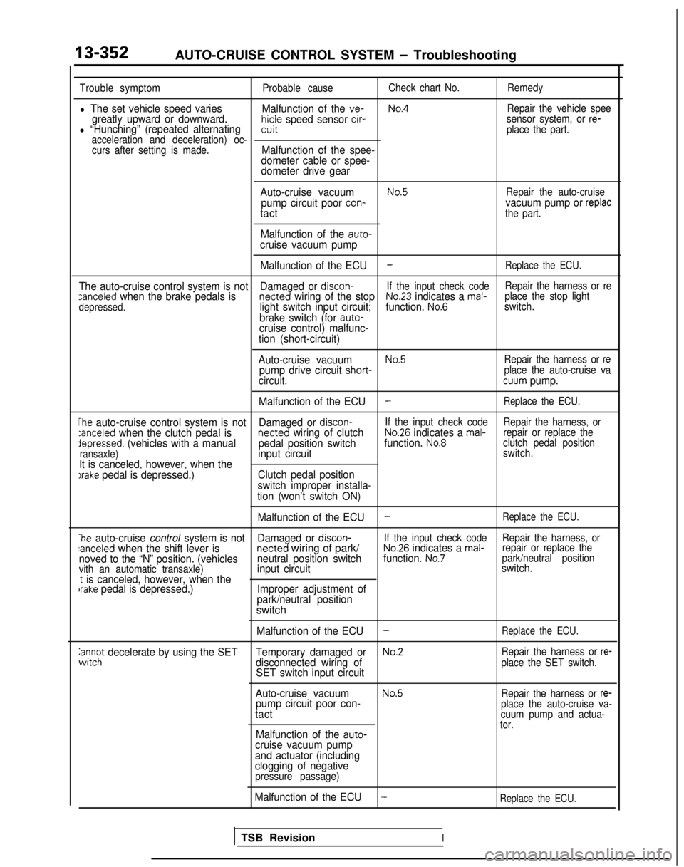
13-352AUTO-CRUISE CONTROL SYSTEM - Troubleshooting
Trouble symptomProbable causeCheck chart No.
Remedy
l The set vehicle speed varies Malfunction of the ve-No.4Repair the vehicle speegreatly upward or downward.hicle speed sensor cir-l “Hunching” (repeated alternatingsensor system, or re-witplace the part.
acceleration and deceleration) oc- curs after setting is made.
Malfunction of the spee-
dometer cable or spee-
dometer drive gear
Auto-cruise vacuum
No.5Repair the auto-cruisepump circuit poor con-vacuum pump or replactactthe part.
Malfunction of the auto-cruise vacuum pump Malfunction of the ECU
-Replace the ECU.
The auto-cruise control system is not Damaged or discon-If the input check code Repair the harness or rezanceled when the brake pedals is netted wiring of the stopNo.23 indicates a mal-
depressed.light switch input circuit; function. No.6place the stop light
switch.
brake switch (for auto-cruise control) malfunc-
tion (short-circuit)
Auto-cruise vacuum
No.5Repair the harness or repump drive circuit short- place the auto-cruise va
circuit.cuum pump.
Malfunction of the ECU
-Replace the ECU.
The auto-cruise control system is not Damaged or discon-If the input check code
Repair the harness, or:anceled when the clutch pedal is netted wiring of clutchNo.26 indicates a mal-repair or replace thedepressed. (vehicles with a manual
pedal position switchfunction. No.8clutch pedal position
ransaxle)input circuitswitch.
It is canceled, however, when theIrake pedal is depressed.) Clutch pedal position
switch improper installa-
tion (won’t switch ON)
Malfunction of the ECU
-Replace the ECU.
*he auto-cruise control system is not Damaged or discon-If the input check code
Repair the harness, or:anceled when the shift lever is netted
wiring of park/No.26 indicates a mal-repair or replace the
noved to the “N” position. (vehicles neutral position switchfunction. No.7park/neutral position
vith an automatic transaxle)input circuit switch.t is canceled, however, when thebrake pedal is depressed.)
Improper adjustment of
park/neutral position
switch
Malfunction of the ECU-Replace the ECU.
anc$ decelerate by using the SET Temporary damaged orNo.2Repair the harness or re-disconnected wiring of
SET switch input circuitplace the SET switch.
Auto-cruise vacuumNo.5Repair the harness or re-pump circuit poor con-
tactplace the auto-cruise va-
cuum pump and actua-
tor.Malfunction of the auto-cruise vacuum pump
and actuator (including
clogging of negative
pressure passage)
Malfunction of the ECU-Replace the ECU.
TSB RevisionI
Page 495 of 1273
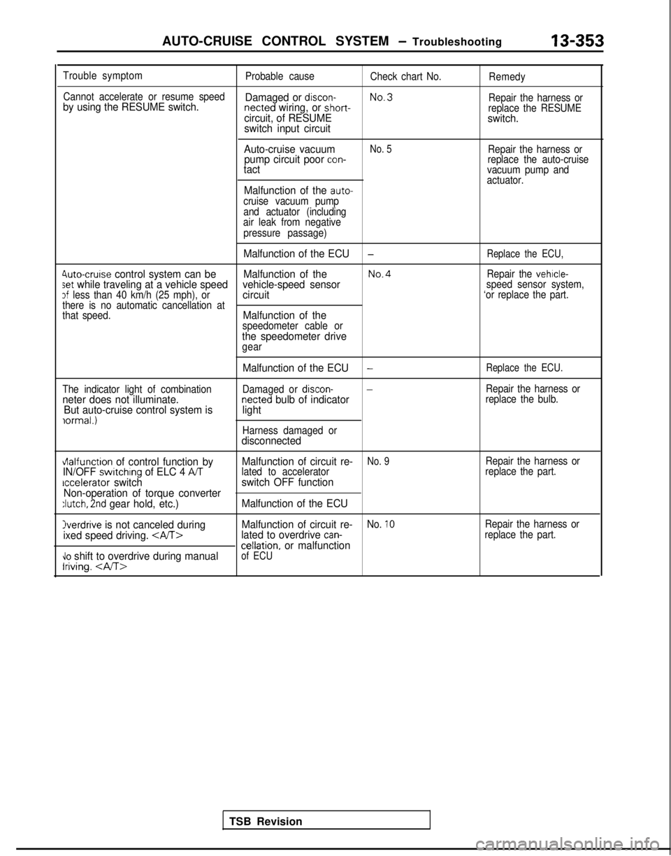
AUTO-CRUISE CONTROL SYSTEM - Troubleshooting13-353
Trouble symptom
Probable causeCheck chart No.Remedy
Cannot accelerate or resume speed
No.3
by using the RESUME switch. Damaged or discon- netted wiring, or short-
Repair the harness orcircuit, of RESUMEreplace the RESUMEswitch.
switch input circuit
Auto-cruise vacuum
No. 5Repair the harness orpump circuit poor con-replace the auto-cruisetactvacuum pump and
actuator.
Malfunction of the auto-cruise vacuum pump
and actuator (including
air leak from negative
pressure passage)
Malfunction of the ECU-Replace the ECU,
4uto-cruise control system can be Malfunction of theNo.4Repair the vehicle-set while traveling at a vehicle speed vehicle-speed sensorspeed sensor system,3f less than 40 km/h (25 mph), orcircuit‘or replace the part.
there is no automatic cancellation at
that speed.
Malfunction of thespeedometer cable orthe speedometer drivegear
The indicator light of combination
neter does not illuminate. But auto-cruise control system is
iormal.)
Malfunction of the ECU-Replace the ECU.
Damaged or discon--Repair the harness ornetted bulb of indicatorreplace the bulb.light
Harness damaged ordisconnected
vlalfunction of control function by Malfunction of circuit re-No. 9Repair the harness orIN/OFF switchrng of ELC 4 ATlated to accelerator
replace the part.accelerator switchswitch OFF function
Non-operation of torque converter
:lutch, 2nd gear hold, etc.) Malfunction of the ECU
Overdrive is not canceled during Malfunction of circuit re-No. 10Repair the harness or
ixed speed driving. lated to overdrive can-replace the part.cellation, or malfunction\lo shift to overdrive during manualIriving.
of ECU
TSB Revision
Page 504 of 1273
13-362AUTO-CRUISE CONTROL SYSTEM - Troubleshooting
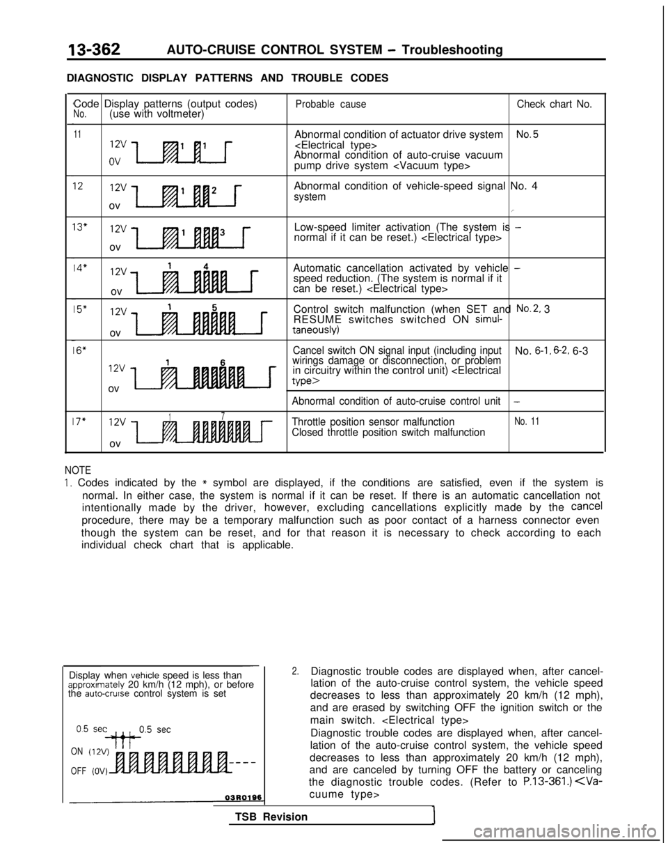
DIAGNOSTIC DISPLAY PATTERNS AND TROUBLE CODES Code Display patterns (output codes)
No.(use with voltmeter)
11
xJa-.tu
Probable causeCheck chart No.
Abnormal condition of actuator drive systemNo.5
Abnormal condition of auto-cruise vacuum
pump drive system
1212vAbnormal condition of vehicle-speed signal No. 4systemov/
13"12vLow-speed limiter activation (The system is -normal if it can be reset.)
ov
14*12v14Automatic cancellation activated by vehicle -speed reduction. (The system is normal if it
ov can be reset.)
15"12v15Control switch malfunction (when SET and No.2, 3
RESUME switches switched ON simul-
ovtaneously)
16"Cancel switch ON signal input (including inputNo. 6-1, 6-2. 6-3
12v16wirings damage or disconnection, or problemin circuitry within the control unit)
we>
Abnormal condition of auto-cruise control unit-
17"12v17Throttle position sensor malfunctionNo. 11
Closed throttle position switch malfunction
ov
NOTE
1. Codes indicated by the * symbol are displayed, if the conditions are satisfied, even if the system is
normal. In either case, the system is normal if it can be reset. If ther\
e is an automatic cancellation not
intentionally made by the driver, however, excluding cancellations explicitly made by the
cancel
procedure, there may be a temporary malfunction such as poor contact of \
a harness connector even
though the system can be reset, and for that reason it is necessary to c\
heck according to each individual check chart that is applicable.
ON
OFF
-
Display when vehicle speed is less thanapproximately 20 km/h (12 mph), or before
the auto-cruise control system is set
0.5 set
++P5 setDiagnostic trouble codes are displayed when, after cancel-
lation of the auto-cruise control system, the vehicle speed
decreases to less than approximately 20 km/h (12 mph),
and are canceled by turning OFF the battery or canceling
the diagnostic trouble codes. (Refer to
P.13-361.)
TSB Revision
2.Diagnostic trouble codes are displayed when, after cancel-
lation of the auto-cruise control system, the vehicle speed
decreases to less than approximately 20 km/h (12 mph),
and are erased by switching OFF the ignition switch or the
main switch.
Page 545 of 1273
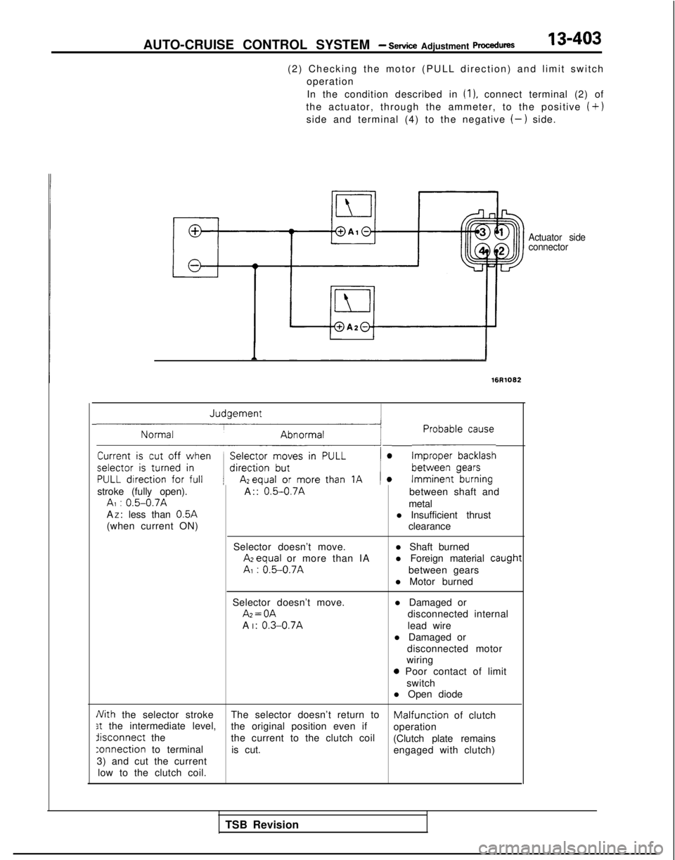
AUTO-CRUISE CONTROL SYSTEM - Service Adjustment procedures13-403
(2) Checking the motor (PULL direction) and limit switch
operation
In the condition described in
(1). connect terminal (2) of
the actuator, through the ammeter, to the positive
(+)
side and terminal (4) to the negative (-) side.
Actuator side
connector
16R1082
~1 L-E~~~~~~
stroke (fully open). A:: 0.5-0.7Abetween shaft andAI : 0.5-0.7Ametal
A Z: less than 0.5A
l Insufficient thrust
(when current ON) clearance
Selector doesn’t move. l Shaft burned Azequal
or more than IA l Foreign material
caugt
AI : 0.5-0.7Abetween gears
l Motor burned
Selector doesn’t move. Az=OA
A I:
0.3-0.7A
l Damaged or
disconnected internal
lead wire
l Damaged or disconnected motor
wiring
0 Poor contact of limit
switch
l Open diode
Nith the selector stroke The selector doesn’t return toMalfunciion of clutch3t the intermediate level,
the original position even if
operationdisconnect
the
the current to the clutch coil
(Clutch plate remains
:onnection to terminalis cut. engaged with clutch)
3) and cut the current
low to the clutch coil.
1t
TSB Revision
Page 546 of 1273
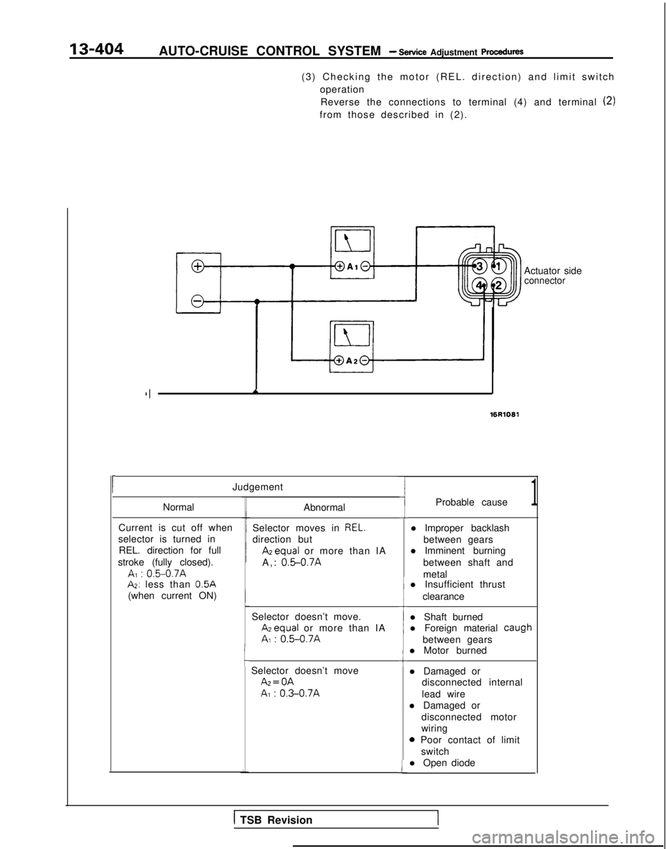
13-404AUTO-CRUISE CONTROL SYSTEM - Service Adjustment procedures
(3) Checking the motor (REL. direction) and limit switchoperationReverse the connections to terminal (4) and terminal
(2)
from those described in (2).
c
Actuator sideconnector
II*
16R1081
Judgement
Normal
Current is cut off when
selector is turned in REL. direction for full
stroke (fully closed).
A, : 0.5-0.7AAZ: less than
0.5A
(when current ON) Abnormal
Selector moves in
REL.
direction but
Apequa or more than IA
A,: 0.5-0.7A
Selector doesn’t move. ATequal
or more than IA
AI : 0.5-0.7AI
cSelector doesn’t move Az=OA
A, :
0.3-0.7A
-I
1
I
i
1
Probable cause1
l Improper backlash
between gears
l Imminent burning
between shaft and
metal
l Insufficient thrust
clearance
l Shaft burned
l Foreign material caugh
between gears
l Motor burned
l Damaged or
disconnected internal
lead wire
l Damaged or
disconnected motor
wiring
0 Poor contact of limitswitch
l Open diode
1 TSB RevisionI
Page 547 of 1273

AUTO-CRUISE CONTROL SYSTEM - Sewice Adjustment Procedures
ECU connector terminals
19171513ll><7531
2018161412 101 98642
16A1060
ELECTRONIC CONTROL UNIT (ECU) SIGNAL CIRCUIT
CHECK
Disconnect the connector of the ECU, and then check at the
body side wiring harness according to the chart below.
IG SW: Ignition switch
MAIN SW: Main switch
OD SMI: Overdrive switch
Termi-~ Connection or mea-
nal
~
sured part Measure-
Tester con-
ment item nection
Check conditions
Standard
I-
I-
1 ~
Actuator (motor) Resistance1 - “‘2Actuator selector Approx. 120
(Fully closed position)
1
2
3I Stop light switchVoltage3-Ground ~
IG S/W ON, Main SW O
N
Battery positive
~
(for auto-cruise ~
control cancellation)
j )
i (Don’t press brake pedal.)j voltage
and actuator (clutch)I Press brake pedal after checkingBattery positive
5 1 Power supply (MAIN)
/ above.voltage -0V
Voltage5-Ground
1 IG S/W
ON, Main S/W ONBattery positive
voltage
6None-i -i-
7 1
Power supply (IGz)Voltag
e
7-GroundIG SfW O
N
Battery positive
voltage
8*z ~
On-board diagnostic--i- -
TSB Revision
9Accelerator pedal Voltageg-GroundIG SW O
N
Battery positive
switch
(Accelerator pedal free)voltage
1 Press accelerator pedal after/ Battery positive
II checking above.[voltage -0V
IO I Vehicle speed sensor
Voltage1 O-Ground’ W
ith the ignition key at the ON
’ ~
4 voltage
position, slowly turn the speedom- changes/
ca-
eter cable. ble
rotation
11SET switch
Continuity1 l-Ground ’ SET switch ON (Press) Continuity
SET switch OFF (Release) No continuity
12OD switch
13RESUME switch 1
Voltage
Continuity
12-GroundIG SNV ON OD SW ON position
Battery positive
voltage
OD
SW OFF position ~
OV
13-Ground ~
RESUME switch ON (Turn) Continuity
; RESUME switch OFF (Release)
No continuity
14’2 ~
4 A/T control module( -/- I- !
-
I/15 1 Stop light switch load
~
Voltage15-Ground’ Press the brake pedal.Battery positiveside/voltage
16 j Ground
Continuity1 16-GroundAt all times ~
Continuity