1989 MITSUBISHI GALANT wiring
[x] Cancel search: wiringPage 151 of 1273
FUEL SYSTEM
13-9
r
I Connector
6FU1216
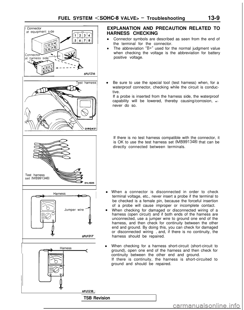
EXPLANATION AND PRECAUTION RELATED TO
HARNESS CHECKING
l Connector symbols are described as seen from the end of
the terminal for the connector.
lThe abbreviation “B+”
used for the normal judgment value
when checking the voltage is the abbreviation for battery positive voltage.
Test harness
set (MB991348)
Jumper wire
&6FU1217
Harness <
LQ
Q,
6FUlZlBj
l
Be sure to use the special tool (test harness) when, for a
waterproof connector, checking while the circuit is conduc-
tive. If a probe is inserted from the harness side, the waterproof
capability will be lowered, thereby causing/corrosion, SO
never do so.
If there is no test harness compatible with the connector, it
is OK to use the test harness set (MB991348)
that can be
directly connected between terminals.
l When a connector is disconnected in order to check terminal voltage, etc., never insert a probe if the terminal to
be checked is a female pin, because the forceful insertion
of a probe will cause improper or incomplete contact.
l When checking for damaged or disconnected wiring of a
harness (open circuit) and if both ends of the harness are
unconnected, use a jumper wire to ground one end of the
harness, and then check for continuity between the other
end and ground. By doing this, you can check for damaged
or disconnected wiring
., and, if there is no continuity, the
harness should be repaired.
l When checking for a harness short-circuit (short-circuit to
ground), open one end of the harness and then check for
continuity between the other end and ground.
If there is continuity, the harness is short-circuited to
ground and should be repaired.
TSB Revision
Page 187 of 1273
FUEL .SYSTEM
Inspection of MFI Components13-45
ENGINE CONTROL MODULE POWER GROUND MlJYDAA
control module Engine control module
p7 v
101
F
106
Engine control module connector
01A0191
OlL0838
1
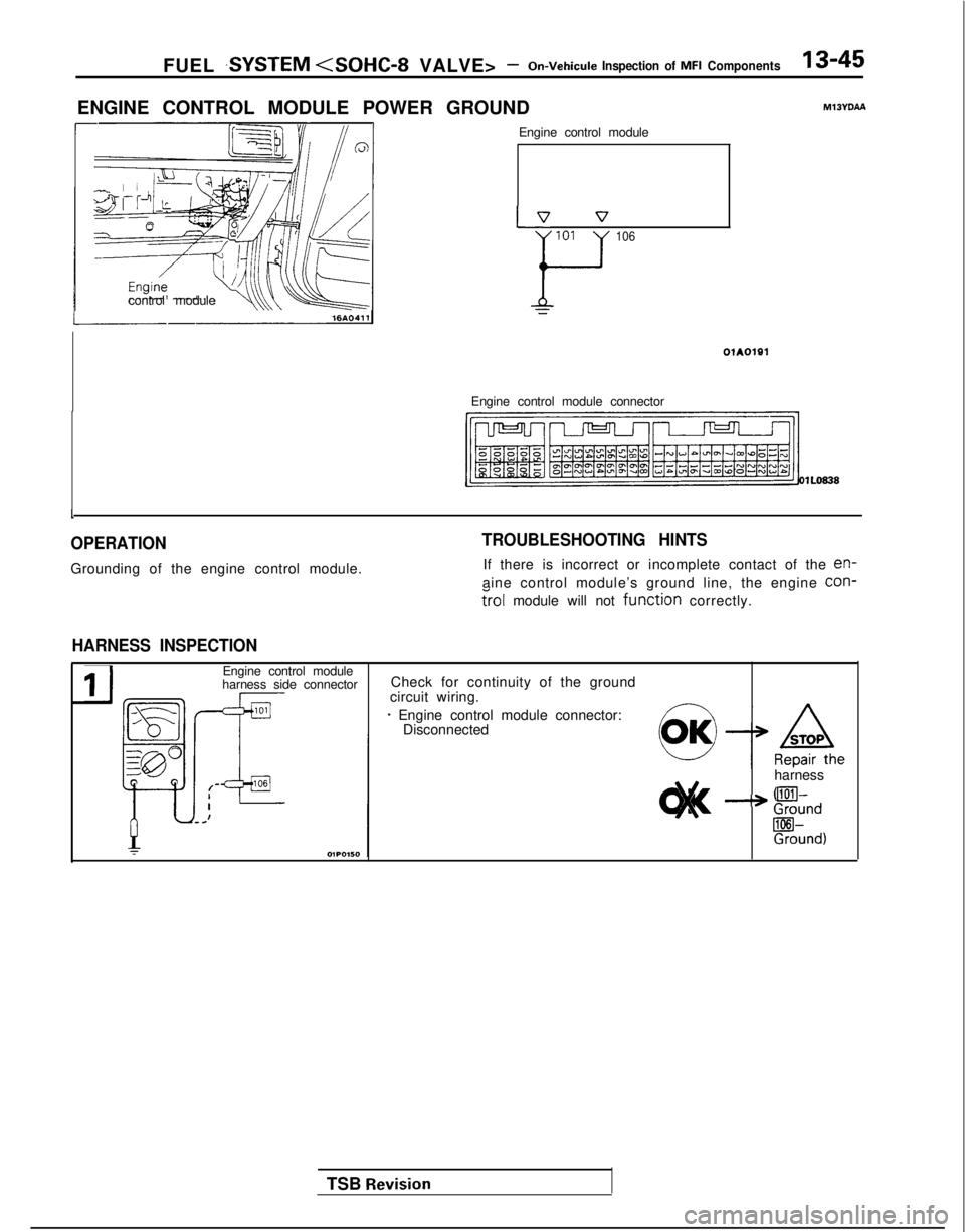
OPERATION
Grounding of the engine control module.
TROUBLESHOOTING HINTS
If there is incorrect or incomplete contact of the en-
aine control module’s ground line, the engine con-
?rol module will not function correctly.
HARNESS INSPECTION
TSB Revision
IJ
Engine control module
harness side connector Check for continuity of the ground
circuit wiring.
* Engine control module connector: Disconnected
harness
--* !!%nd
Rind)
Page 222 of 1273
13-80 FUEL SYSTEM
VEHICLE SPEED SENSOR
Vehicle speed sensor
Vehicle speed sensor
IV1
-errnInafoltage
102418
Frwyy 1/
Component side@ connector
Component side@ connector
6FU1410
Engine control
module
5v
MIBVPAA
Vehicle speed sensor
Engine control module connector Vetwle
speed [km/h (mph)]
16245
1
OlLO838
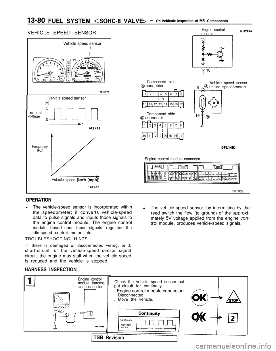
OPERATION
l
The vehicle-speed sensor is incorporated within
the speedometer; it converts vehicle-speed
data to pulse signals and inputs those signals to
the engine control module. The engine control
module, based upon those signals, regulates the
idle-speed control motor, etc.
TROUBLESHOOTING HINTS l
The vehicle-speed sensor, by intermitting by the
reed switch the flow (to ground) of the approxi-
mately
5V voltage applied from the engine con-
trol
module, produces vehicle-speed signals.
If ‘there is damaged or disconnected wiring, or a
short-circuit, of the vehicle-speed sensor signal
circuit. the engine may stall when the vehicle speed is reduced and the vehicle is stopped.
HARNESS INSPECTION
-side connector
_--- _
ia
_, - .,
:_--
gp
p
L
11Engine control
module harness
=l01AOW(1
I
Check the vehicle speed sensor out-
put circuit for continuity.
. Engine control module connector: Disconnected
. Move the vehicle.
) TSBRevision
Page 245 of 1273
FUEL SYSTEM
TSB Revision
---
I g$qfq, tcJ-s6FUO633
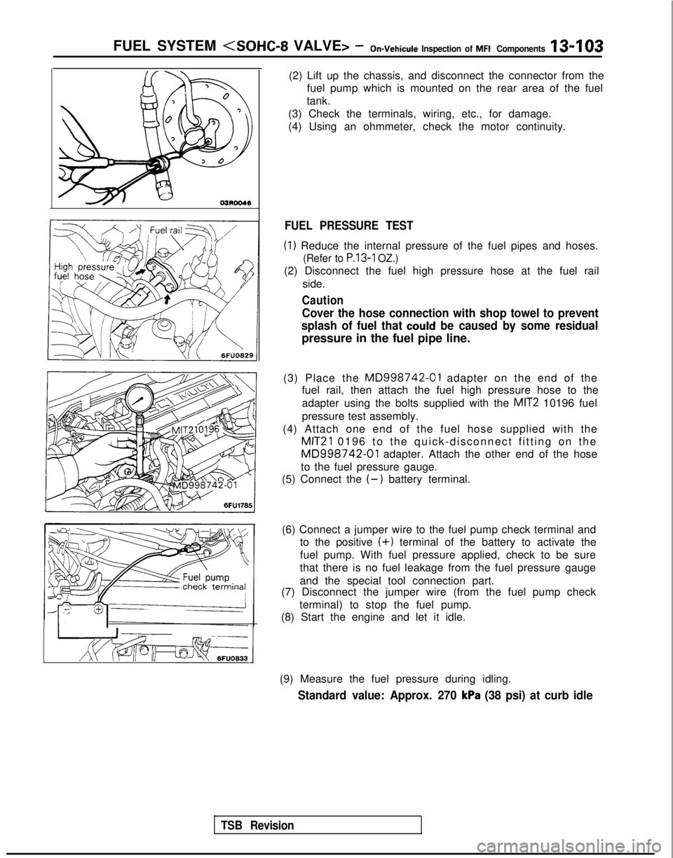
(2) Lift up the chassis, and disconnect the connector from the
fuel pump which is mounted on the rear area of the fuel
tank.
(3) Check the terminals, wiring, etc., for damage.
(4) Using an ohmmeter, check the motor continuity.
FUEL PRESSURE TEST
(1) Reduce the internal pressure of the fuel pipes and hoses.
(Refer to P.13-1 OZ.)
(2) Disconnect the fuel high pressure hose at the fuel rail
side.
Caution
Cover the hose connection with shop towel to prevent
splash of fuel that
could be caused by some residual
pressure in the fuel pipe line.
(3) Place the
MD998742-01 adapter on the end of the
fuel rail, then attach the fuel high pressure hose to the
adapter using the bolts supplied with the
MIT2 10196 fuel
pressure test assembly.
(4) Attach one end of the fuel hose supplied with the
MIT21 0196 to the quick-disconnect fitting on the
MD998742-01 adapter. Attach the other end of the hose
to the fuel pressure gauge.
(5) Connect the
(-) battery terminal.
(6) Connect a jumper wire to the fuel pump check terminal and to the positive
(+) terminal of the battery to activate the
fuel pump. With fuel pressure applied, check to be sure
that there is no fuel leakage from the fuel pressure gauge
and the special tool connection part.
(7) Disconnect the jumper wire (from the fuel pump check
terminal) to stop the fuel pump.
(8) Start the engine and let it idle.
(9) Measure the fuel pressure during idling.
Standard value: Approx. 270 kPa (38 psi) at curb idle
Page 247 of 1273
FUEL SYSTEM
fine probe7FU1264 1
(15) Reduce the internal pressure of the fuel pipes and hoses.
(Refer to
P.13-102.)
(16) Disconnect the fuel pressure gauge and the special toolsfrom the fuel rail.
Caution
Because there will be some residual pressure in the fuel
pipe line, use a shop towel to cover so that fuel doesn’t
splatter.
(17)Replace the O-ring at the end of the fuel high-pressure
hose with a new one. (18)After
connecting the fuel high-pressure hose to the fuel
rail, tighten the installation bolt.
(19)Check to be sure that there is no fuel leakage.
@ Apply battery voltage to the terminal for activation of the fuel pump so as to activate the fuel pump.
@ With fuel pressure applied, check for leakage of the fuel
line.
INSPECTION OF ENGINE CONTROL MODULE
TERMINAL VOLTAGEMl 3ZALBa
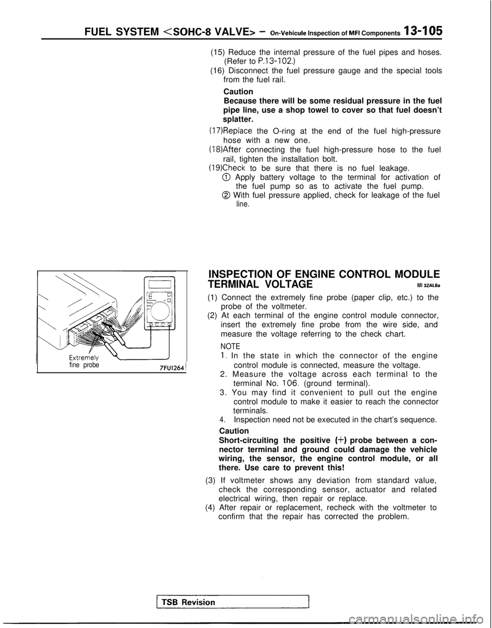
(1) Connect the extremely fine probe (paper clip, etc.) to the probe of the voltmeter.
(2) At each terminal of the engine control module connector,
insert the extremely fine probe from the wire side, and
measure the voltage referring to the check chart.
NOTE
1. In the state in which the connector of the engine
control module is connected, measure the voltage.
2. Measure the voltage across each terminal to the
terminal No. 106.
(ground terminal).
3. You may find it convenient to pull out the engine control module to make it easier to reach the connector
terminals.
4.Inspection need not be executed in the chart’s sequence.
Caution
Short-circuiting the positive
(+) probe between a con-
nector terminal and ground could damage the vehicle
wiring, the sensor, the engine control module, or all
there. Use care to prevent this!
(3) If voltmeter shows any deviation from standard value, check the corresponding sensor, actuator and related
electrical wiring, then repair or replace.
(4) After repair or replacement, recheck with the voltmeter to confirm that the repair has corrected the problem.
Page 441 of 1273
FUEL SYSTEM
MFI Components13-299
OPERATION
l The amount of air taken in during idling is
regulated by the opening and closing of the
servo valve located in the air passage that
bypasses the throttle valve.
l The servo valve is opened or closed by the
activation of the stepper motor (incorporated
within the idle air control motor) in the forward
or reverse direction.
TROUBLESHOOTING HINTS
Hint 1: If the number of stepper motor steps increases to
IOO- 120 steps or decreases
to 0 step, the cause may be presumed to be a malfunction of the stepper motor or
damaged or disconnected wiring of the
harness.
Hint 2: If the number of stepper motor steps
deviates from the standard value even
though the results of the checking of the
harness of the idle air control motor and of
the comoonent
itself indicate no abnormal
condition, the cause may be presumed to be one of the following.
INSPECTION
Using Scan tool
lBattery power supply is supplied, by way of the
multiport fuel injection relay, to the coil of the
stepper motor. The engine control module
switches ON the power transistors (located
within the engine control module) in sequential
order, and, when current flows to the stepper motor coil, the stepper motor is activated in the
forward or reverse direction.
(1) Improper adjustment of the standard
idling speed.
(2) Deposits adhered to the throttle valve.
(3) Leakage of air into the intake manifold
from a gasket gap, etc.
(4) Incomplete close contact of the EGRvalve seat.
(5) Incomplete combustion within the
cylinder.
(Malfunction of the spark plugs, the
ignition coil, the iniectors,
the
com- pression
pressure, etc.)
FunctionItem No.Data display Check conditions Load conditionsStandard value
Data reading 45Steppermotor steps. Engine coolant tempera-
. Air conditioning
4-14Step
ture:switch: OFF
(185-205°F)
. Lights, electrical cooling
:$b::pfan and accessories: OFF
. Transaxle: neutral
. Closed throttle switch: ON
- Air conditioning 20-60 Step
switch: ON
(The compressor clutchshould be activated when
the air conditioning switch;J-;;o~P
is switched ON.)* Engine: idling
1;:!,1;:!,
/!-I\/!-I\
f$&$:”f$&$:”
! ,‘,! ,‘,
4);4);
;jj\(Q(j!jGZ-);jj\(Q(j!jGZ-)
lili
q#Q~Hq#Q~HF]F]
ii 2 L J 2 L ~ -0SClllO 4ii 2 L J 2 L ~ -0SClllO 4
NOTE
When the vehicle is new (driven approximately 500 km (300 miles) or l\
ess) the number of steps may be about
30 steps greater than the standard value indicated above.
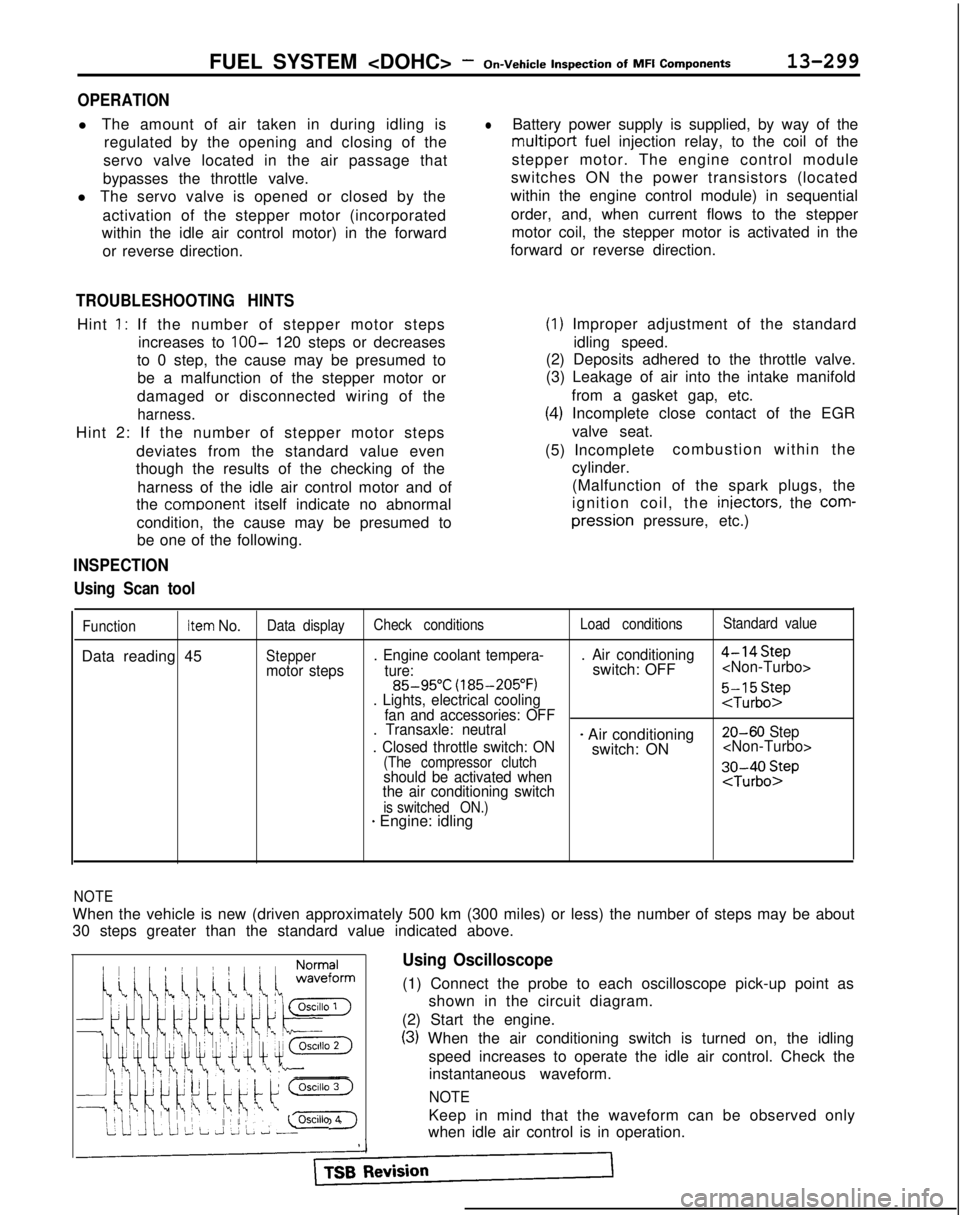
Using Oscilloscope
(1) Connect the probe to each oscilloscope pick-up point as
shown in the circuit diagram.
(2) Start the engine.
(3) When the air conditioning switch is turned on, the idling speed increases to operate the idle air control. Check theinstantaneous waveform.
NOTE
Keep in mind that the waveform can be observed only
when idle air control is in operation.
Page 477 of 1273
AUTO-CRUISE CONTROL SYSTEM - Troubleshooting
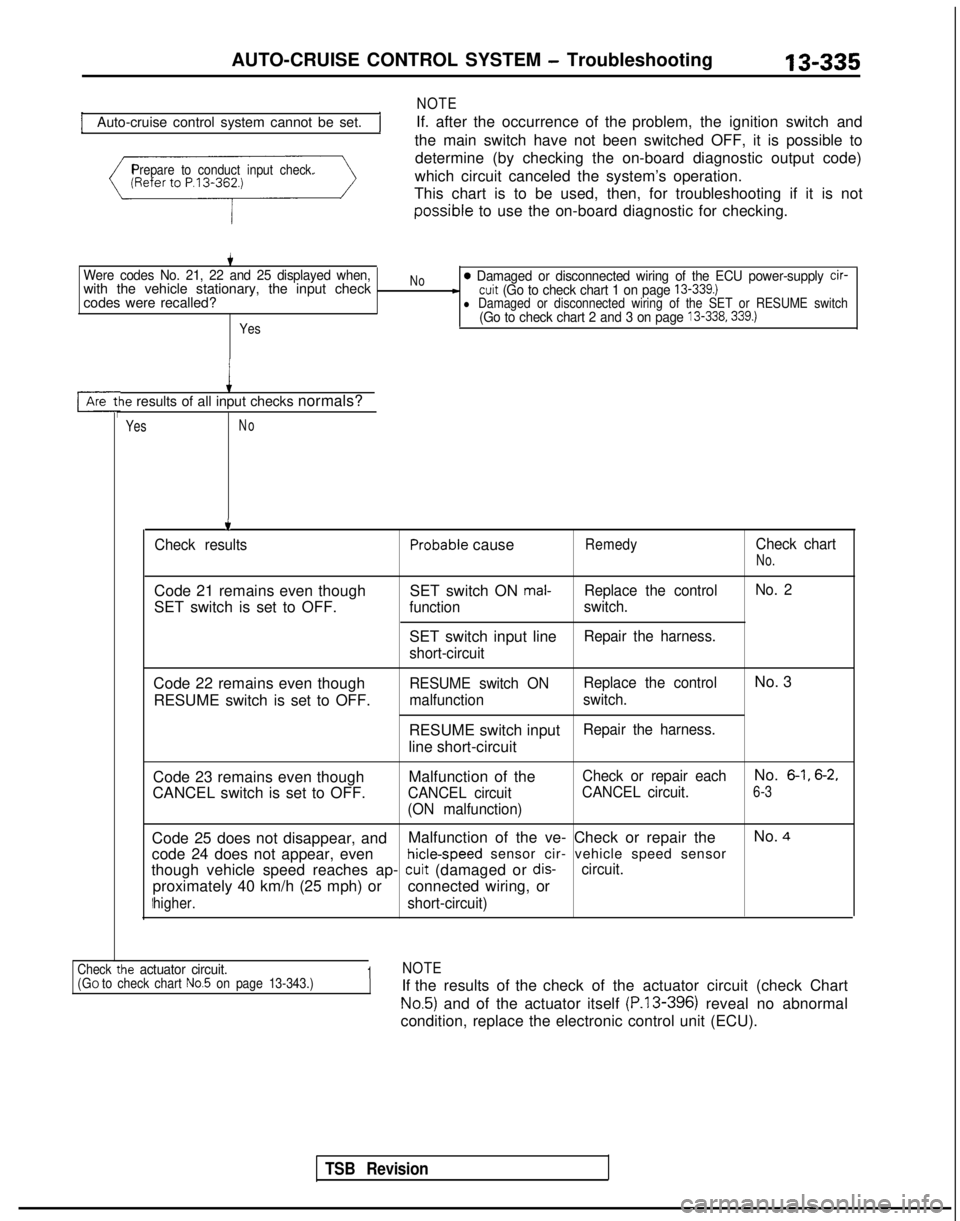
Auto-cruise control system cannot be set.
NOTE
If. after the occurrence of the problem, the ignition switch and
the main switch have not been switched OFF, it is possible to
Prepare to conduct input check.determine (by checking the on-board diagnostic output code)
which circuit canceled the system’s operation.
This chart is to be used, then, for troubleshooting if it is not possible
to use the on-board diagnostic for checking.
Were codes No. 21, 22 and 25 displayed when,with the vehicle stationary, the input check
codes were recalled?
Yes
No0 Damaged or disconnected wiring of the ECU power-supply cir--cuit (Go to check chart 1 on page 13-339.)l Damaged or disconnected wiring of the SET or RESUME switch(Go to check chart 2 and 3 on page 13-338.339.)
le results of all input checks normals?
YesNo
.t
TSB Revision
.
Check resultsProbable causeRemedyCheck chart
No.
Code 21 remains even though
SET switch is set to OFF. SET switch ON mal-Replace the control
No. 2
function switch.
SET switch input lineRepair the harness.
short-circuit
Code 22 remains even though RESUME switch is set to OFF.RESUME switch ON Replace the controlNo. 3
malfunction
switch.
RESUME switch inputRepair the harness.
line short-circuit
Code 23 remains even though
CANCEL switch is set to OFF. Malfunction of the
CANCEL circuit
(ON malfunction) Check or repair each
No. 6-1, 6-2,
CANCEL circuit.6-3
Code 25 does not disappear, and
Malfunction of the ve- Check or repair the No. 4
code 24 does not appear, even hicle-speed
sensor cir- vehicle speed sensor
though vehicle speed reaches ap-
cuit (damaged or dis-circuit.
proximately 40 km/h (25 mph) or connected wiring, or
higher.short-circuit)
ie actuator circuit.1NOTECheck tl(GO to check chart No.5 on page 13-343.)If the results of the check of the actuator circuit (check Chart
No.5) and of the actuator itself (P.13-396) reveal no abnormal
condition, replace the electronic control unit (ECU).
Page 478 of 1273
13-336AUTO-CRUISE CONTROL SYSTEM - Troubleshooting
Probable cause1 Check chart No.1 Remedy
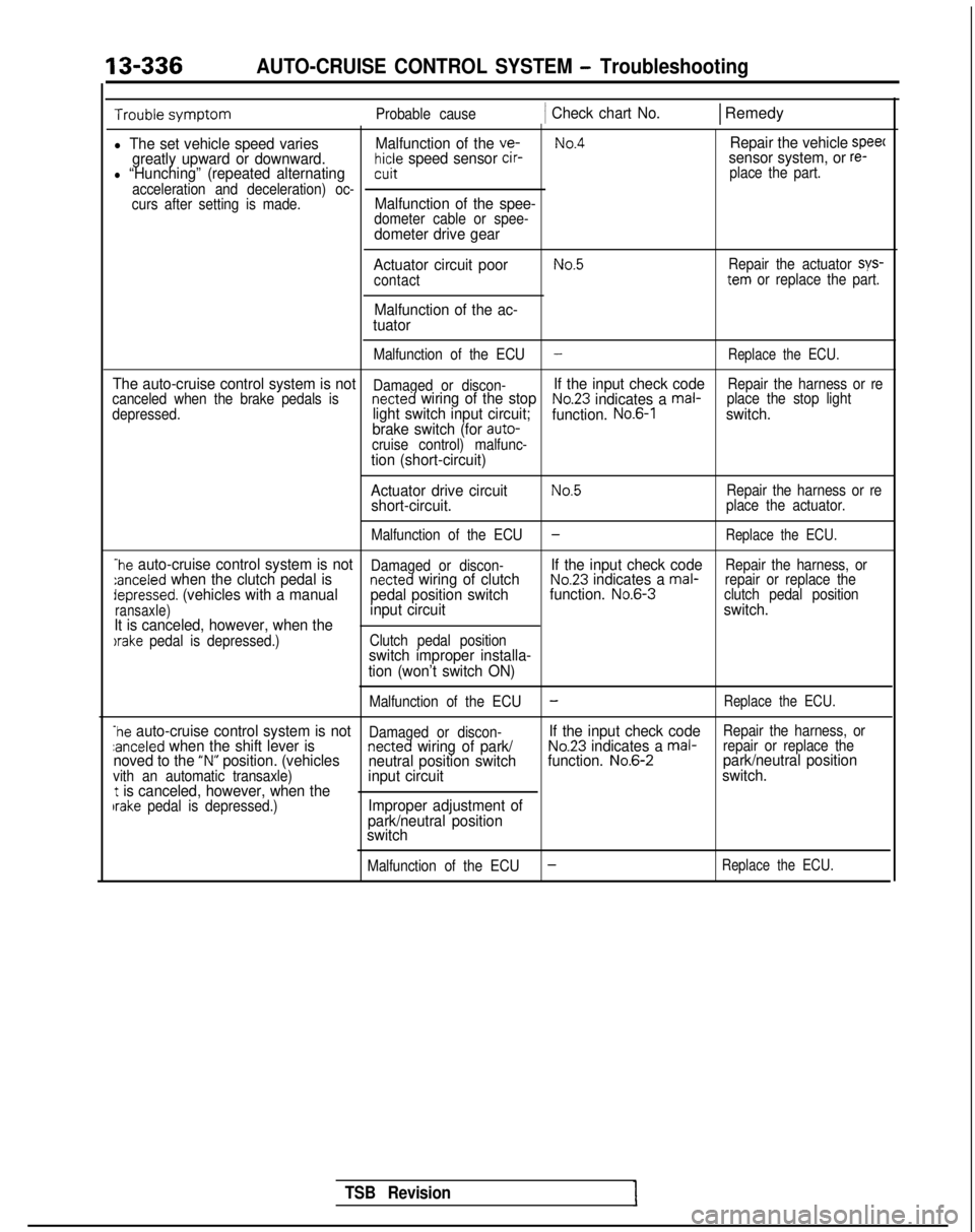
l The set vehicle speed variesMalfunction of the ve-No.4Repair the vehicle speec
greatly upward or downward.hicle speed sensor cir-sensor system, or re-l “Hunching” (repeated alternatingcuit place the part.
acceleration and deceleration) oc-
curs after setting is made.
Malfunction of the spee-dometer cable or spee-dometer drive gear
Actuator circuit poor
contact
Malfunction of the ac-
tuator
No.5Repair the actuator sys-tern or replace the part.
Malfunction of the ECU
-Replace the ECU.
The auto-cruise control system is notDamaged or discon-If the input check codeRepair the harness or re
canceled when the brake pedals isnetted wiring of the stopNo.23 indicates a mal- place the stop light
depressed.light switch input circuit; function. No.6-1switch.
brake switch (for auto-
cruise control) malfunc-
tion (short-circuit)
Actuator drive circuit
No.5Repair the harness or reshort-circuit.place the actuator.
Malfunction of the ECU
-Replace the ECU.
-he auto-cruise control system is notDamaged or discon-If the input check codeRepair the harness, or:anceled when the clutch pedal isnetted wiring of clutchNo.23 indicates a mal- repair or replace thedepressed. (vehicles with a manual pedal position switchfunction. No.6-3
clutch pedal position
ransaxle)input circuit switch.
It is canceled, however, when the
)rake pedal is depressed.) Clutch pedal positionswitch improper installa-
tion (won’t switch ON)
Malfunction of the ECU-Replace the ECU.
-he auto-cruise control system is notDamaged or discon-If the input check codeRepair the harness, orzanceled when the shift lever isnetted wiring of park/No.23 indicates a mal- repair or replace thenoved to the “N” position. (vehicles
neutral position switch function. No.6-2park/neutral positionvith an automatic transaxle)input circuit switch.t is canceled, however, when theIrake pedal is depressed.)Improper adjustment of
park/neutral position
switch
Malfunction of the ECU-Replace the ECU.
TSB Revision