Page 753 of 1273
AUTOMATIC TRANSAXLE - Troubleshooting23-47
Check the resistance betweenShort-circuit, or dam-
terminal 1 of the solenoid valve aged or disconnected
connector and the transaxle case. wiring4 4
2.9
+ 0.3Q/20°C (68°F)1Replace the PCSV.
t
Solenoid valve
connector terminals
PCSVTCC solenoid
;g;:;
Connect 12V between the trans-
axle case and terminal 1;
switch ON and OFF and check for
operation noise.
1
Noise exists. 1Replace the PCSV.1J
NormalI
valve connector and the transaxleAlShort-circuit, or
dam-aoed or disconnected-=!-- -’ -.
wrringI
I
f
22.3 k l.5Q/20°C (68°F)Replace the SCSV.
4II,1 I \
Connect
12V between the trans-
axle case and terminal 3 or 4; switch ON and OFF and check for
operation noise of the solenoid
valve, and check the valve stroke.
TSB Revision
yF$$;za;:pulated in /
+
Noise exists. 4
Normal
1Replace the SCSV.]
Page 755 of 1273
AUTOMATIC TRANSAXLE - Troubleshootinn
9. Torque
conver-
ter clutch
(TCC)solenoid Check the resistance between
terminal 2 of the solenoid valve connector and the transaxlecase.
Short-circuit, or dam-
too low
or too aged or disconnected
wiring
I
Solenoid valve
4*
(Standard value: 3 Q/2O”CReplace the TCC solenoid
/-connector terminals
Connect 12V between the trans-
*Stickingis
usually at the
1750338
4
Normal1release side.
4
Replace the TCC solenoid
W
ith the accelerator pedal not
depressed, check the resistance between terminals 1 and 2.
1
Continuity exists (resistance: 0)
Problem not solved.
1
1
E/l2
171096 Replace the accelerator
switch.
W
ith the accelerator pedal de-
No continuity (resistance:
CQ)I
TSB Revision
+
Normal
Page 767 of 1273
AUTOMATIC TRANSAXLE - Troubleshooting
TAILLIGHT
RELAY
I334m6678
____-__-_--__-----------2 c-43
01OA
@
c-01"'&,"'$,5‘r
AUTO-CRUISECDWROL-UNIT
(RG)@ (GL)
1 9
g (GR)I 'f% I
3 I
C-16
1OA 1
-1
!I ”
5
5
>
1
3
5
5
e
'8 C-32
D-47
POWER/
ECONOMY CHANGE OVER
SWITCH
1
J/B(TAIL)
IPOYER
BY 12,
RLBW 1::s"/I-
;B li:m ki
YR5
(RG) 17<
ELC4-SPEEDAUTOMATIC
FGEt;;kE
MODULE
REMARK
tMARK INDICATES THE OPTIONAL WIRINGHARNESS FOR AUTO-CRUISE CONTROL SYSTEM.
TSB Revision\
Page 769 of 1273
AUTOMATIC TRANSAXLE - Troubleshooting
MFI CONTROL UNIT
THROTTLEW#ON
n cc
E-01
mfY;KFU1 IBLE23
J/B(GROUND)
C-32 xi.16
I
3 C-42E
5 13 ~1~11~1Ef13(14l15#61117 J/B
c-38 4
T
41cu
-c-58>0
i
.___ -’s_Q- -----
fl
,---_-_---
5v 9-T
A-45
1
A-46
a
m
m2
65
+ KlCKDOWNJ/B
iv0 SWITCH4 c-38 wEl
qREMARKtMARK INDICATES THE OPTIONAL WIRINGHARNESS FOR AUTO-CRUISE CONTROL SYSTEM.
TSB Revision
Page 773 of 1273
AUTOMATIC TRANSAXLE - Troubleshooting23-67
c-12
MFI CONTROL UNIT
D i51w,
D 157BiI
-- ____ ------d
SERVO SWITCHPULSE
GENERATOR
A-45
qREMARKtMARK INDICATES THE OPTIONAL WIRINGHARNEBS FOR AUTO-CRUISE CONTROL SYSTEM.
TSB Revision
Page 775 of 1273
AUTOMATIC TRANSAXLE - Troubleshooting23-69
@L$GHT
I
r-l I J’Bn-aa
I?I4I-RI, I i-lu-47
POWER/ECONOMYUIA# OVER
AU’
II 1I l+i
I ~lc!IJ/BI '0(TAIL)AUTO-CRUIGECONTROL-UNIT%C-01 lF3=wnnmsn
@m ;B
I II I
-~----------------------~-------i-----” 1 jiE;;;;/F5
@ BYI’ I
C-60-1
ELC4-SPEEDAUTOMATIC
mN;;;LE
MODULE
REMARKXMARK INDICATES THE OPTIONAL WIRINGHARNESS FOR AUTO-CRUISE CONTROL SYSTEM.
1 TSB Revision1
Page 777 of 1273
AUTOMATIC TRANSAXLE - Troubleshooting23-71
SUB FUIBLELINK 1d
l-I!!1
c-12
MFI CONTROL UNIT
11 14THROTTLEW$W~~ON
\I
RHEOSTAT
E-01
19pis%Jg
tIGNITION
!~!#!ISTORI
J/B(RHEO)
d- -1113_--------------:1
r
_____-- _-em-------:T64
m
I
/4
1
t- LII
ElELC 4-SPEED AUTOMATICTRANSAXLE SOLENOID VALVE
Z#&ATOR
A-45
REMARK
XMARK INDICATES THE OPTIONAL WIRINGHARNESS FOR AUTO-CRUISE CONTROL SYSTEM.
1 TSB RevisionI
Page 796 of 1273

AUTOMATIC TRANSAXLE - Service Adjustment Procedures
1_DTZii+!ilz$F~
I
\
B
-g----J a
----- .f-
iL (i
&Fgi
Tit\I;; ;gTjqy ?“,,,,,,
FWD . . . Up to MODEL 1990IOil pan gasketsurface
case0
1750435
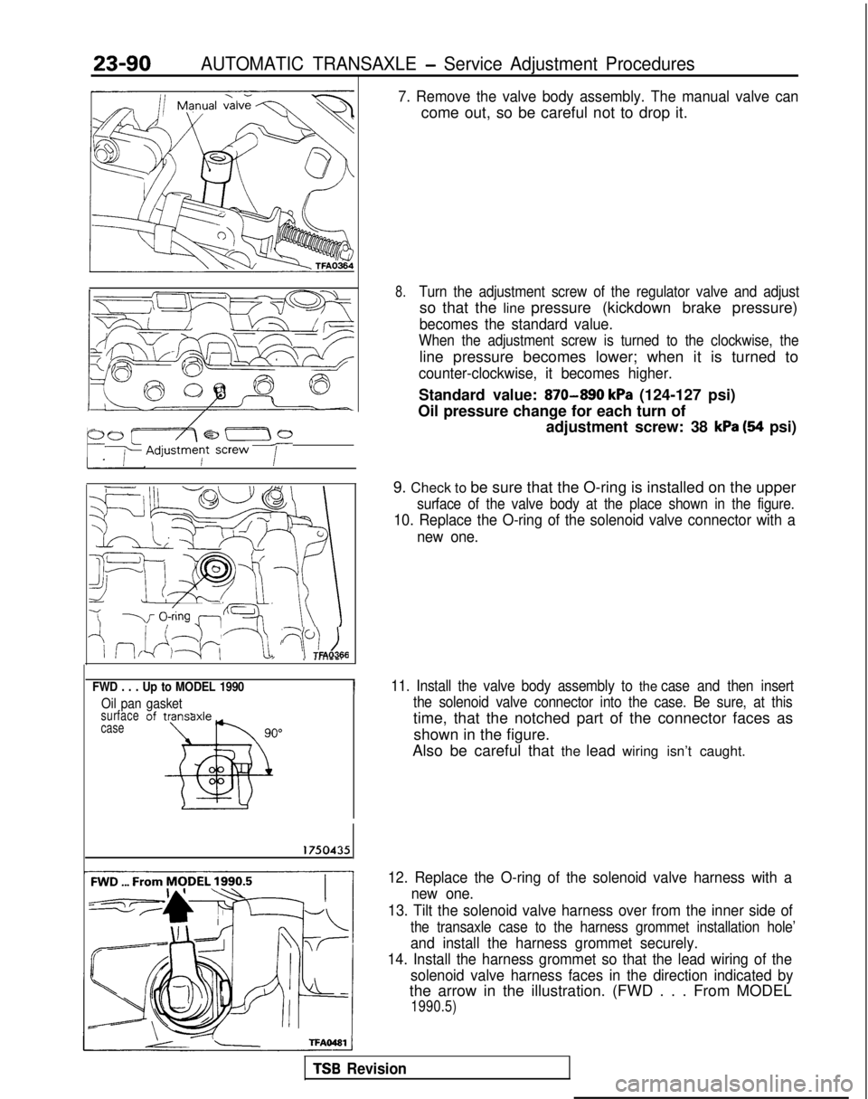
7. Remove the valve body assembly. The manual valve can
come out, so be careful not to drop it.
8.Turn the adjustment screw of the regulator valve and adjust
so that the line pressure (kickdown brake pressure)
becomes the standard value.
When the adjustment screw is turned to the clockwise, the
line pressure becomes lower; when it is turned to
counter-clockwise, it becomes higher.
Standard value: 870-890 kPa (124-127 psi)
Oil pressure change for each turn of adjustment screw: 38
kPa (94 psi)
9. Check to be sure that the O-ring is installed on the upper
surface of the valve body at the place shown in the figure.
10. Replace the O-ring of the solenoid valve connector with a new one.
11. Install the valve body assembly to the case and then insert
the solenoid valve connector into the case. Be sure, at this
time, that the notched part of the connector faces as
shown in the figure.
Also be careful that the lead wiring isn’t caught.
TSB Revision
12. Replace the O-ring of the solenoid valve harness with a new one.
13. Tilt the solenoid valve harness over from the inner side of
the transaxle case to the harness grommet installation hole’
and install the harness grommet securely.
14. Install the harness grommet so that the lead wiring of the solenoid valve harness faces in the direction indicated by
the arrow in the illustration. (FWD . . . From MODEL
1990.5)