1989 MITSUBISHI GALANT wiring
[x] Cancel search: wiringPage 1026 of 1273
ACTIVE-ELECTRONIC CONTROL SUSPENSIONService Adjustment- Procedures33B-87
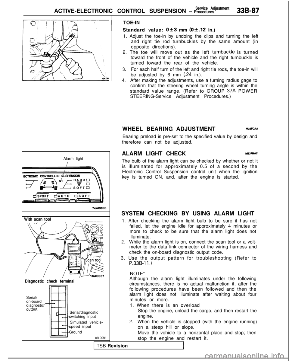
Alarm light
With scan tool
Diagnostic check terminal
Serial/
on-board
diagnostic’
outwt
TSB RevisionI
Serial/diagnostic
-switching input
Simulated vehicle-
-speed input
-Ground
16LOO91
!
TOE-IN
Standard value:
Ok3 mm (Of.12 in.)
1. Adjust the toe-in by undoing the clips and turning the left and right tie rod turnbuckles by the same amount (in
opposite directions).
2. The toe will move out as the left turnbuckle
is turned
toward the front of the vehicle and the right turnbuckle is
turned toward the rear of the vehicle.
3.For each half turn of the left and right tie rods, the toe-in will
be adjusted by 6 mm
(.24 in.).
4.After making the adjustments, use a turning radius gage to confirm that the steering wheel turning angle is within the
standard value range. (Refer to GROUP 37A
POWER
STEERING-Service Adjustment Procedures.)
WHEEL BEARING ADJUSTMENT
M33FcAA
Bearing preload is pre-set to the specified value by design and
therefore can not be adjusted.
ALARM LIGHT CHECK
MPFNAC
The bulb of the alarm light can be checked by whether or not it is illuminated for approximately 0.5 of a second by the
Electronic Control Suspension control unit when the ignition
key is turned ON, and, after the engine is started.
SYSTEM CHECKING BY USING ALARM LIGHT 1. After checking the alarm light bulb to be sure it has not failed, let the engine idle for approximately 4 minutes ormore to check to be sure that the alarm light does not
illuminate.
2.While the alarm light is on, connect the scan tool or a volt- meter to the data link connector of the wiring harness and
check the on-board diagnostic output code.
3. Use the output pattern for troubleshooting (Refer to
P.33B-11.)
NOTE*
Although the alarm light illuminates under the following
circumstances, there is no actual malfunction if, after the
following procedures have been followed and then the
alarm light does not illuminate after waiting about four
minutes or more.
1. When there is an overload Stop the engine, unload the cargo, and then restart the
engine.
2.When the vehicle is stopped (with the engine running)
on a steep hill or slope.Move the vehicle to a horizontal place and stop; then
stop the engine and restart it.
Page 1037 of 1273
33B-98ACTIVE-ELECTRONIC CONTROL SUSPENSION - Strut Assembly i
SERVICE POINTS OF REMOVALM33lBAE
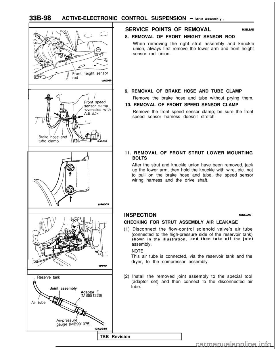
8. REMOVAL OF FRONT HEIGHT SENSOR RODWhen removing the right strut assembly and knuckleunion, always first remove the lower arm and front height
sensor rod union. l1RoooP
-
,Reserve tank
Joint assembly
Adaptor E
1 -1210289
9. REMOVAL OF BRAKE HOSE AND TUBE CLAMP
Remove the brake hose and tube without prying them.
10. REMOVAL OF FRONT SPEED SENSOR CLAMP
Remove the front speed sensor clamp; be sure the front
speed sensor harness doesn’t stretch.
11. REMOVAL OF FRONT STRUT LOWER MOUNTING
BOLTS
After the strut and knuckle union have been removed, jack up the lower arm, then hold the knuckle with wire, etc. not
to pull on the brake hose and tube, the speed sensor wiring harness and the drive shaft.
INSPECTION
M33LCAC
CHECKING FOR STRUT ASSEMBLY AIR LEAKAGE
(1) Disconnect the flow-control solenoid valve’s air tube (connected to the high-pressure side of the reservoir tank)
shown in the illustration, and then take off the join
t
assembly.
NOTE
This air tube is connected, via the reservoir tank and the dryer, to the compressor assembly.
(2) Install the removed joint assembly to the special tool (adaptor set) and then connect to the disconnected air
tube.
TSB Revision
Page 1064 of 1273
ACTIVE-ELECTRONIC CONTROL SUSPENSION - ~~~,:B,:w,r 336-125
Paint
12Ao323
AIR COMPRESSOR
REMOVAL AND INSTALLATION
31(Refer to GROUP ISAir cleaner.)
Post-installation Operationl Installation of Air Cleaner
(Refer to GROUP 15-Air cleaner.)
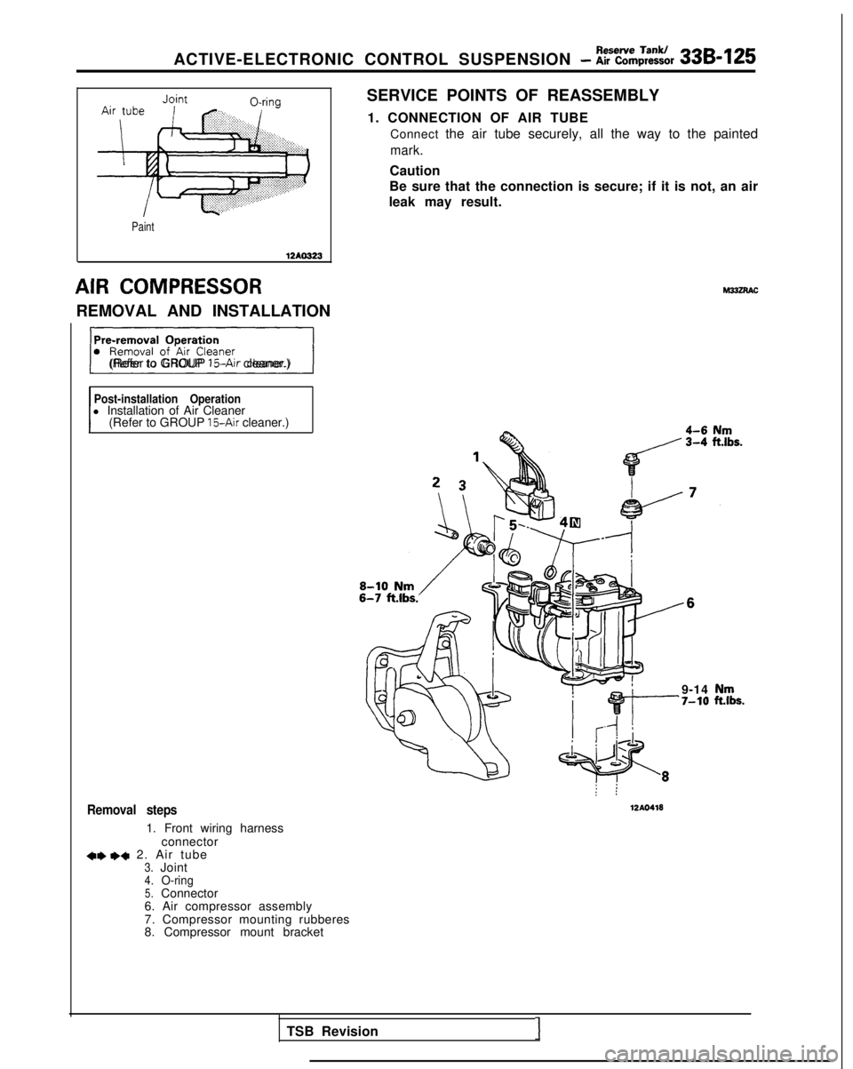
Removal steps
1. Front wiring harness
connector
+* I)+ 2. Air tube3.Joint4.O-ring5.Connector
6. Air compressor assembly
7. Compressor mounting rubberes
8. Compressor mount bracket SERVICE POINTS OF REASSEMBLY
1. CONNECTION OF AIR TUBE Connect the air tube securely, all the way to the painted
mark.
Caution
Be sure that the connection is secure; if it is not, an air
leak may result.
: :
12AO418
9-14‘7-10
TSB Revision1
Page 1065 of 1273
33B-126ACTIVE-ELECTRONIC CONTROL SUSPENSION - Air compressor
L
MB991 075
w
I12AO443
12A0444
Exhaust solenoid valveJoint
Air iJbex ~~~~~~~~8,:,,.: :.:.:.:.: .,._,:.................:.
..........................................
i==Ja.................:.: . .......................
SERVICE POINTS OF REMOVAL
2. REMOVAL OF AIR TUBE Caution1. In order to prevent dust, dirt and other foreign material from getting into the air tube and air
compressor openings, cover these opening with
vinyl tape or similar material.
2. Be careful not to bend the air tubes.
INSPECTION
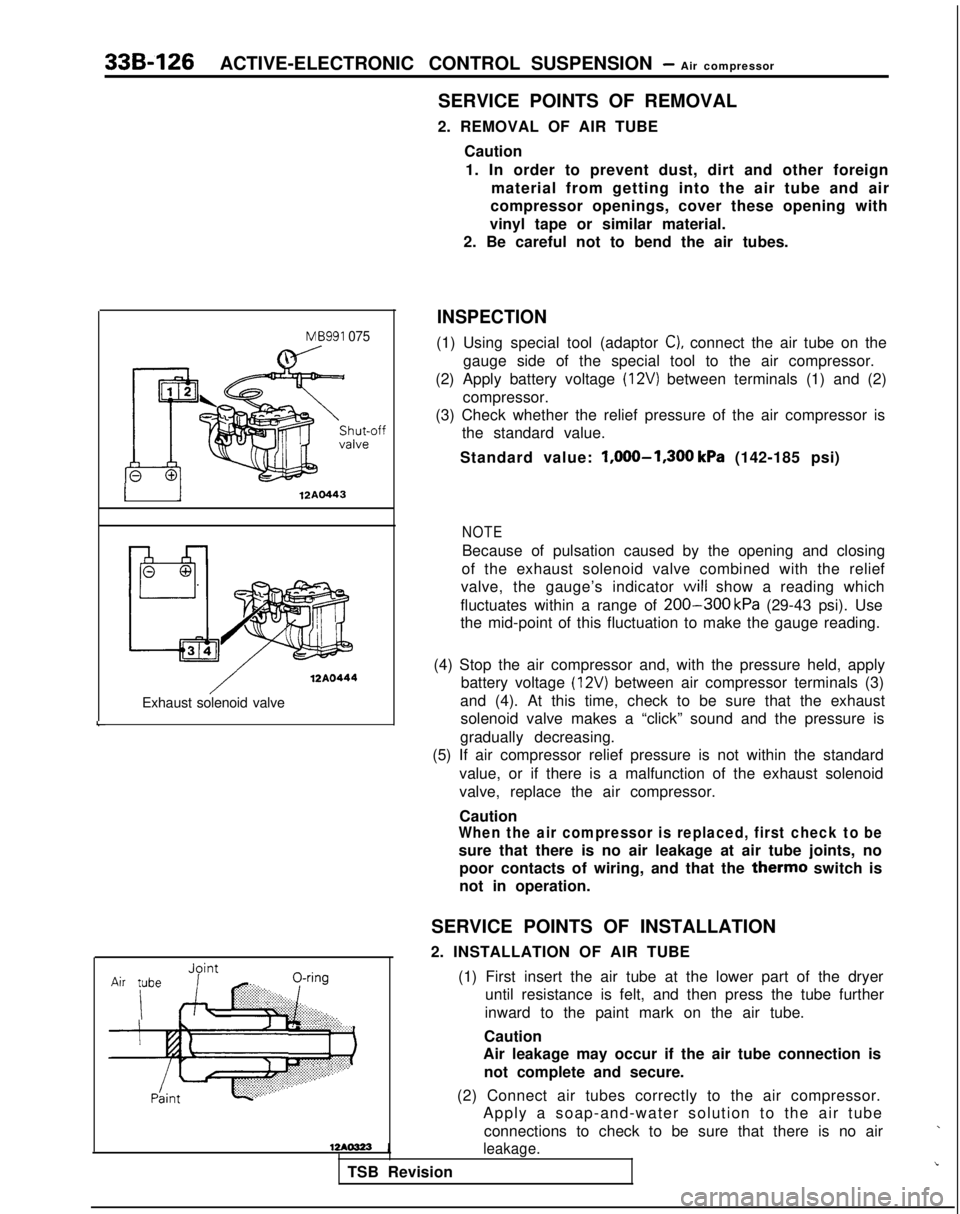
(1) Using special tool (adaptor C), connect the air tube on the
gauge side of the special tool to the air compressor.
(2) Apply battery voltage
(12V) between terminals (1) and (2)
compressor.
(3) Check whether the relief pressure of the air compressor is the standard value.
Standard value: l,OOO-1,300
kPa (142-185 psi)
NOTE
Because of pulsation caused by the opening and closing
of the exhaust solenoid valve combined with the relief
valve, the gauge’s indicator
will show a reading which
fluctuates within a range of
200-300 kPa (29-43 psi). Use
the mid-point of this fluctuation to make the gauge reading.
(4) Stop the air compressor and, with the pressure held, apply battery voltage
(12V) between air compressor terminals (3)
and (4). At this time, check to be sure that the exhaust solenoid valve makes a “click” sound and the pressure is
gradually decreasing.
(5) If air compressor relief pressure is not within the standard
value, or if there is a malfunction of the exhaust solenoid
valve, replace the air compressor.
Caution
When the air compressor is replaced, first check to be
sure that there is no air leakage at air tube joints, nopoor contacts of wiring, and that the
therm0 switch is
not in operation.
SERVICE POINTS OF INSTALLATION
2. INSTALLATION OF AIR TUBE
(1) First insert the air tube at the lower part of the dryeruntil resistance is felt, and then press the tube further
inward to the paint mark on the air tube.
Caution
Air leakage may occur if the air tube connection is
not complete and secure.
(2) Connect air tubes correctly to the air compressor. Apply a soap-and-water solution to the air tube
connections to check to be sure that there is no air
leakage.
TSB Revision
Page 1074 of 1273
ACTIVE-ELECTRONIC CONTROL SUSPENSION - Heiaht Sensor 33B-135
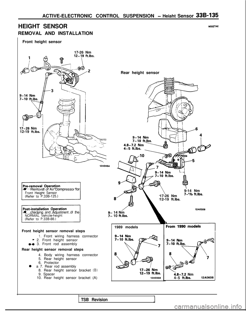
HEIGHT SENSOR
REMOVAL AND INSTALLATION
Front height sensor
17-26 Nm
li-26 Nm
12-19 ft.lbs.
l Removal of Air Compressor for
17-26 Nm
I- I” n.,os.
12-19 ft.lbs.
l checking and Adjustment of the14 Nm
10 ftlbs.
1989 models
Front height sensor removal steps
1. Front wiring harness connector* 2. Front height sensore+ 3. Front rod assembly
Rear height sensor removal steps 4. Body wiring harness connector5. Rear height sensor
6. Protector
l a 7. Rear rod assembly
8. Rear height sensor bracket
(B)9. Spacer
10. Rear height sensor bracket (A)l2A0358 12AO464
M332TAE
Rear height sensor
9-14 Nm
- .a #.&IL- 12AO358
‘19901
i.8-7.2 Nm
4-5 ft.lbs.12A0608
TSB Revision
Page 1143 of 1273
35-22SERVICE BRAKES- Anti-lock Braking System Troubleshooting
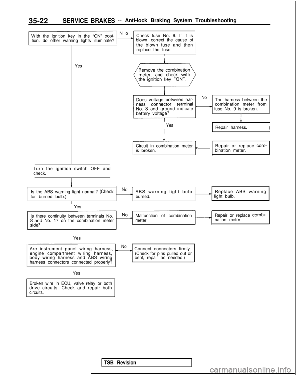
- N
o
With the ignition key in the “ON” posi-
Check fuse No. 9. If it is
tion. do other warning lights illuminate?
* blown, correct the cause of
the blown fuse and thenreplace the fuse.
I
Yes
Turn the ignition switch OFF and check.
4II., III,
Is the ABS warning light normal? (CheckNo cABS warning light bulb Replace ABS warning
for burned bulb.)burned.* light bulb.
I
Yes
NoThe harness between the
combination meter from
* fuse No. 9 is broken.
1
Repair harness.I
Circuit in combination metercRepair or replace com-
is broken. bination meter.
Yes
Is there continuity between terminals No.NoMalfunction of combination Repair or replace combi-
;,d”,l” No. 17 on the combination meter -meter
nation meter
Yes
Are instrument panel wiring harness, _
Noc Connect connectors firmly.
engine compartment wiring harness,
body wiring harness and ABS wiring
harness connectors connected properly? (Check for pins pulled out or
bent, repair as needed.)
Yes
Broken wire in ECU, valve relay or both
drive circuits. Check and repair both
circuits.
TSB Revision
Page 1161 of 1273
SERVICE BRAKES - Anti-lock Braking System Troubleshooting
W
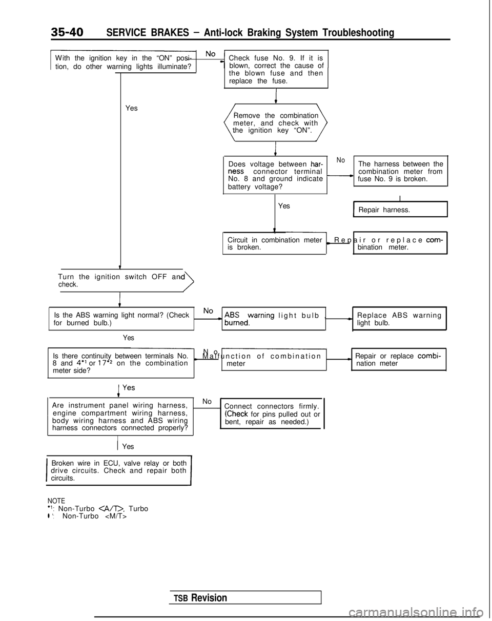
ith the ignition key in the “ON” posi- No
Check fuse No. 9. If it is
tion, do other warning lights illuminate? blown, correct the cause of
-T-
Yesthe blown fuse and then
replace the fuse.I
Remove the combination
meter, and check with
the ignition key “ON”.
I
Does voltage between har-NoThe harness between the ness
connector terminal
No. 8 and ground indicate
-combination meter from
fuse No. 9 is broken.
battery voltage?
I
Yes Repair harness.
Circuit in combination meter
is broken.
L Repair or replace com-
bination meter.
Turn the ignition switch OFF an
check.
I
Is the ABS warning light normal? (CheckNo
for burned bulb.)c A$Eedyrning light bulb
,
c Replace ABS warning
light bulb.
Yes
Is there continuity between terminals No. No -
8 and 4” or 17’2 on the combinationI Malfunction of combinatio
n
meter
I Repair or replace combi-
meter side? nation meter
Are instrument panel wiring harness, No
-~
engine compartment wiring harness, . Connect connectors firmly.
body wiring harness and ABS wiring
(Check for pins pulled out or
harness connectors connected properly? bent, repair as needed.)
I
1 Yes
I
Broken wire in ECU, valve relay or both
drive circuits. Check and repair both
circuits.
I
NOTE‘1: Non-Turbo . Turbol *:Non-Turbo
TSB Revision
Page 1190 of 1273
SERVICE BRAKES - Service Adjustment Procedures35-69
(5) The probable cause if the output voltage is 50 mV or lower, or if the one-side deflection width of the
oscilloscope’s waveform is 70
mV or lower
Probable causes Remedy
Excessive clearance between the speed sensor pole
piece and rotor Adjust to the standard value.
Foreign material attached to the speed sensor pole
pieceRemove the foreign material.
Damaged speed sensor pole pieceReplace the speed sensor.
Damaged rotor teeth~~~ rReplace the rotor.
Loose speed sensor or rotor installation bolt I
Tighten to the specified torque.
1
NOTE
The speed sensor internal resistance and harness side are normal.
Caution
It is conceivable, because the movement of a speed-sensor cable “foll\
ows” the movement of the front
or rear suspension, that the damaged wiring condition may be apparent on\
ly during travel on poor
road surfaces, and may be normal on better road surfaces. Therefore, whe\
n measuring the output
voltage of a speed sensor, recheck the condition of the cable connection\
s by removing the clamp and pulling the cable and bending it near the clamp position in order to che\
ck for the existence of damaged
wiring.
1/21314j51617)61Q~10~11~12)13~14~15)16~17~1~~19~20~21~22~23~24~25~26(27~26~2Q~30(31~32~33~34~35~
Check connector
74=f=n
ECU
*
Body harnessMB991 356fl 14N018C
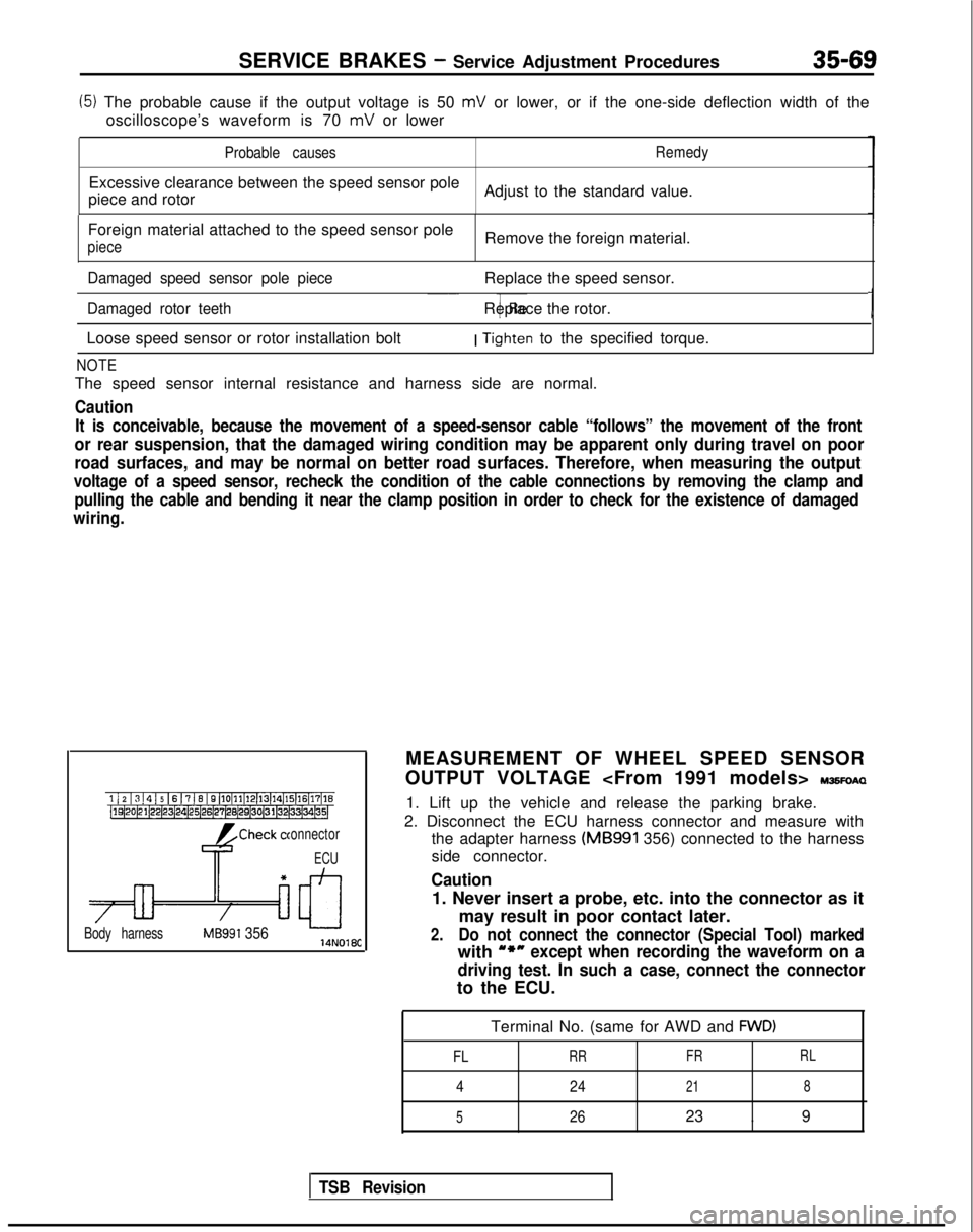
MEASUREMENT OF WHEEL SPEED SENSOR
OUTPUT VOLTAGE
IWSFOAQ
1. Lift up the vehicle and release the parking brake.
2. Disconnect the ECU harness connector and measure with the adapter harness (MB991
356) connected to the harness
side connector.
Caution
1. Never insert a probe, etc. into the connector as it
may result in poor contact later.
2.Do not connect the connector (Special Tool) marked
with u*nexcept when recording the waveform on a
driving test. In such a case, connect the connector
to the ECU.
Terminal No. (same for AWD and
FWD)
FL
RR FRRL
4
24218
5
2623 . 9
TSB Revision