1989 MITSUBISHI GALANT wiring
[x] Cancel search: wiringPage 982 of 1273
ACTIVE-ELECTRONIC CONTROL SUSPENSION - Troubleshooting 33B-43
Diagnostic
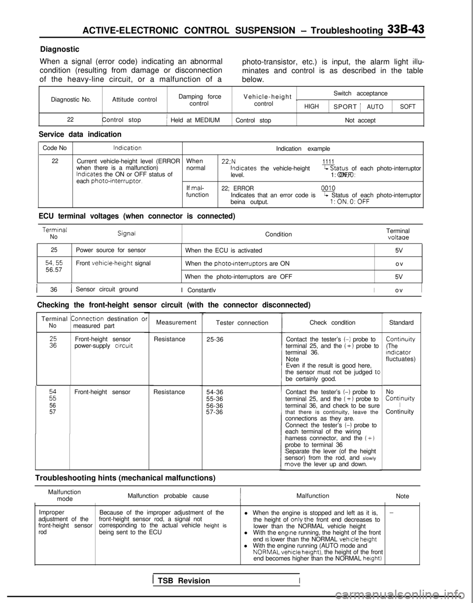
When a signal (error code) indicating an abnormal
condition (resulting from damage or disconnection
of the heavy-line circuit, or a malfunction of a photo-transistor, etc.) is input, the alarm light
illu-
minates and control is as described in the table
below.
Diagnostic No. Attitude control Damping force
Vehicle-height
~Switch acceptance
control control
HIGHSPORT 1AUTOSOFT
22
Control stopj Held at MEDIUM Control stop Not accept
Service data indication
Code No lndrcation
Indication example
22Current vehicle-height level (ERRORWhen 22:N1111when there is a malfunction)
normallndrcates
the ON or OFF status of lndtcates
the vehicle-height-Status of each photo-interruptor
level. 1: ON,O: OFF
each
photointerruptor.If mal-22; ERRORfunction
0010
Indicates that an error code isL Status of each photo-interruptor
beina output.l:ON.O:OFF
ECU terminal voltages (when connector is connected) Termrnal
NoCondition
Terminalvoltaae
25
54,5556.57Power source for sensor
Front vehicle-herght signal
When the ECU is activated
5V
When the photo-rnterruptors are ON
o
v
When the photo-interruptors are OFF
5V
1 36/ Sensor circuit ground I ConstantlvIo
v
I
Checking the front-height sensor circuit (with the connector disconnect\
ed)
Terminal
Connectron
destination cNomeasured part
:zFront-height sensor
power-supply crrcuit
22
56
57
Front-height sensor
Resistance
brMeasurement
Resistance 25-36Tester connection
54-36
55-36
56-36
57-36
t
Troubleshooting hints (mechanical malfunctions) Check condition
Standard
Contact the tester’s
(-1 probe to Contrnuity
terminal 25, and the ( + ) probe to(Theterminal 36.
rndrcator
Note fluctuates)
Even if the result is good here,
the sensor must not be judged
tcbe certainly good.
Contact the tester’s
(-1 probe to
terminal 25, and the (+ 1 probe to
terminal 36, and check to be sure
that there is continuity, leave the
connections as they are.
Connect the tester’s
(-1 probe to
each terminal of the wiring
harness connector, and the
(+ Jprobe to terminal 36
Separate the lever (of the height
sensor) from the rod, and slowly
nave the lever up and down.
No Continurty
IContinuity
Malfunction mode Malfunction probable cause
Malfunction
Note
Improper Because of the improper adjustment of the
-adjustment of the
front-height sensorfront-height sensor rod, a signal not
l When the engine is stopped and left as it is,
corresponding to the actual vehicle height is the height of onlythe front end decreases to
rodbeing sent to the ECU lower than the NORMAL vehicle height
l With the engrne running, the height of the front
end IS lower than the NORMAL vehicle
height
l With the engine running (AUTO mode and NORMALvehicle
hetght). the height of the front
end becomes higher than the NORMAL helght)
1 TSB RevisionI
Page 984 of 1273
ACTIVE-ELECTRONIC CONTROL SUSPENSION - Troubleshootina 33B-45
Diagnostic
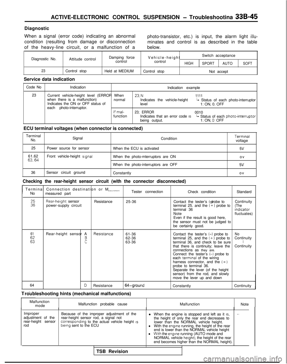
When a signal (error code) indicating an abnormal condition (resulting from damage or disconnection
of the heavy-line circuit, or a malfunction of a photo-transistor, etc.) is input, the alarm light
illu-
minates and control is as described in the table
below.
Diagnostic No. Attitude control
23Control stop
Service data indication Damping force
control
Held at MEDIUM Vehicle-heigh
t
Switch acceptance
control
HIGH SPORT AUTOSOFT
Control stop
Not accept
Code No Indication
Indication example
23 Current vehicle-height level (ERROR When 23;N
1111when there is a malfunction)
normal
Indicates the ON or OFF status of Indicates the vehicle-height
levelL Status of each photo-interruptor
each photo-interruptor. 1: ON, 0. OFF
If mal-23; ERROR0010
function Indicates that an error code IS
being output.L Status of each photointerruptor1: ON, 0. OFF
ECU terminal voltages (when connector is connected) Terminal
No.Signal Condition
25 Power source for sensor
When the ECU is activated
61.62
63,64Front vehicle-height sIgnalWhen the photo-mterruptors are ON
When the photo-interruptors are OFF
36 Sensor circuit ground
Constantly Terminal
voltage
5v
o
v
5V
o
v
Checking the rear-height sensor circuit (with the connector disconnecte\
d)
rTerminal Connection destination or
M
easurement
No measured part Tester connection
Check conditionStandardRear-herght
sensor
power-supply circuit Resistance
25-36 Contact the tester’s (-) probe to
Continuity
terminal 25. and the
(+) probe to(Theterminal 36 indrcator
Note fluctuates)
Even if the result is good here,
the sensor must not be judged to be certainly good.
61
Es
Rear-height sensor A Resrstance
61-36No
F
Contact the tester’s (-)
probe to
62-36 terminal 25, and the ( +) probe toContinuity
63-36 terminal 36, and check to be sureIthat there is continuity; leave the Continuity
connections as they are.
Connect the tester’s
(-1 probe to
each termrnal
of the wiring
harness connector, and the
( +)probe to terminal 36. Separate the lever (of the height
sensor) from the rod, and slowly
move the lever up and down
64
- _. .
DResistance64-groundConstantly Continuity
1 roubleshooting hints (mechanical malfunctions)
Malfunctionmode Malfunction probable cause
MalfunctionNote
Improper Because of the improper adjustment of the l When the engine is stopped and left as it IS,
-adjustment of the
rear-height sensorrear-height sensor rod, a signal not
the height of only the rear end decreases to
rod correspondrng
to the actual vehicle height IS berng
sent to the ECU lower than the NORMAL vehicle height.lWith the engrne running, the height of the rear
end is lower than the NORMAL vehicle height
lWith the engine
running (AUTO mode and
NORMAL vehicle herght). the height of the rear
end becomes higher than the NORMAL height).
TSB Revision
Page 988 of 1273
ACTIVE-ELECTRONIC CONTROL SUSPENSION - Troubleshooting 33B-49
Diagnostic
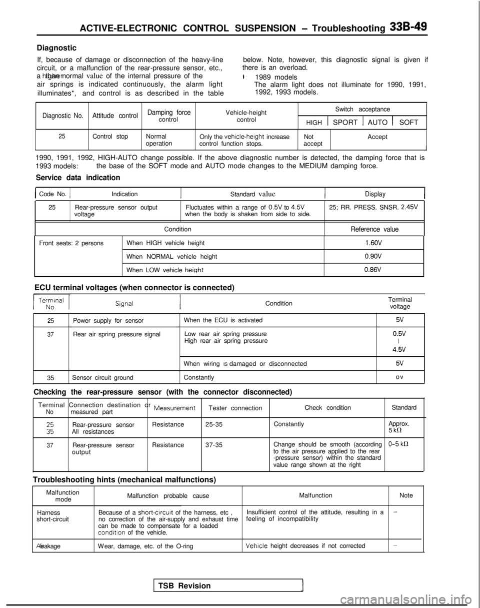
If, because of damage or disconnection of the heavy-line below. Note, however, this diagnostic signal is given if
circuit, or a malfunction of the rear-pressure sensor, etc., there is an overload.
a htgher than normal value of the internal pressure of the
l :1989 models
air springs is indicated continuously, the alarm light The alarm light does not illuminate for 1990, 1991,
illuminates*, and control is as described in the table 1992, 1993 models.
I1
Damping forceVehicle-heightSwitch acceptanceDiagnostic No.Attitude controlcontrol
control
HIGH 1 SPORT 1 AUTO 1 SOFT
25Control stopNormal
Only the vehicle-height
increase Not Accept
operation control function stops. accept
I
1990, 1991, 1992, HIGH-AUTO change possible. If the above diagnostic num\
ber is detected, the damping force that is
1993 models:the base of the SOFT mode and AUTO mode changes to the MEDIUM damping fo\
rce.
Service data indication
1 Code No. 1Indication
Standard valueDisplay
25Rear-pressure sensor output Fluctuates within a range of 0.5V
to 4.5V
25; RR. PRESS. SNSR. 2.45V
voltage when the body is shaken from side to side.
Condition
Reference value
Front seats: 2 persons When HIGH vehicle height
When NORMAL vehicle height
When LOW vehicle
height
1.6OV
0.9ov 0.86V
ECU terminal voltages (when connector is connected) ConditionTerminal
voltage
25Power supply for sensor
37Rear air spring pressure signal When the ECU is activated
Low rear air spring pressure
High rear air spring pressure
5v
0.5vI
4.5v
When wiring IS damaged or disconnected5v
35 Sensor circuit ground
Constantly o
v
Checking the rear-pressure sensor (with the connector disconnected)
Terminal Connection destination or MeasurementNomeasured part
Tester connection
Check condition
Standard
ERear-pressure sensorResistance
25-35 Constantly Approx.
All resistances 5 kll
37Rear-pressure sensor
Resistance
37-35 Change should be smooth (accordingO-5 klloutput to the air pressure applied to the rear
-pressure sensor) within the standard
value range shown at the right
Troubleshooting hints (mechanical malfunctions) Malfunctionmode Malfunction probable cause
Malfunction
Note
Harness
short-circuit Because of a short-circurt
of the harness, etc , Insufficient control of the attitude, resulting in a
-no correction of the air-supply and exhaust time feeling of incompatibility
can be made to compensate for a loaded
condition of the vehicle. Air leakage
Wear, damage, etc. of the O-ring
Vehicle height decreases if not corrected-
TSB Revision
Page 994 of 1273
ACTIVE-ELECTRONIC CONTROL SUSPENSION - Troubleshooting 33B-55
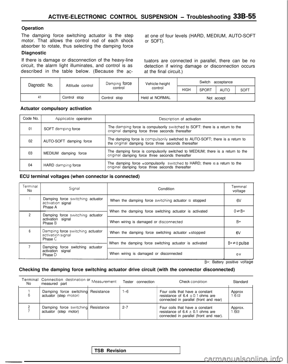
Operation
The damping force switching actuator is the step motor. That allows the control rod of each shock at one of four levels (HARD, MEDIUM, AUTO-SOFT
or SOFT).
absorber to rotate, thus selecting the damping force
Diagnostic
If there is damage or disconnection of the heavy-line
circuit, the alarm light illuminates, and control is as
described in the table below. (Because the
ac-
tuators are connected in parallel, there can be no detection if wiring damage or disconnection occurs
at the final circuit.)
Diagnostic No.Attitude control
41Control stop
Actuator compulsory activation
Damplng forcecontrol
Control stop Vehicle-height
control
Held at NORMALHIGH
Switch acceptance
SPORT AUTO
Not accept
SOFT
Code No.Applrcable operatron Descriptron
of activation
01SOFT damplng force The damplng force is compulsorily swltched to SOFT: there is a return to theonginal damping force three seconds thereafter
02AUTO-SOFT damping force The damping force is compulsorily switched to AUTO-SOFT; there is a return to
the onginal damping force three seconds thereafter
03 MEDIUM damping force The damping force is compulsorily switched to MEDIUM; there is a return \
to the
onginal damping force three seconds thereafter
04 HARD
damplng force The damping force IS compulsorily switched to HARD; there IS a return to theonginal damping force three seconds thereafter
ECU terminal voltages (when connector is connected) Terminal
No
Slgnal
Condition Terminal
voltage
1Damping force swrtchlng
actuatoractlvatlon signal When the damping force switching actuator IS stopped6V
Phase AO=B+2p When the damping force switching actuator is activated
Damping force switching actuator
activation signal
Phase
BWhen wiring is damaged or dlsconnectedB+
6 Damplng
force switchrng
actuatoractivation slgnal
When the damping force switching actuator IS stopped 6V
Phase C
7p When the damping force switching actuator is activated
Damping force switching actuatorB+ = 0 pulse
activation signal
Phase DWhen wiring is damaged or disconnected o
v
B+: Battery positive voltage
Checking the damping force switching actuator drive circuit (with the c\
onnector disconnected)
TSB Revision
Terminal Connection
destination or MeasurementNomeasured part
Tester connection
Check condltlonStandard1
ADamping force switching Resistance 1-6
Four coils that have a constant
actuator (step motor)Approx
resistance of 6.4 i-O.1 ohms are 1611
connected in parallel (front and rear)
2Damping force swltchlng Resistance 2-7
Four coils that have a constant7actuator (step motor) Approx.
resistance of 6.4 t 0.1 ohms are1.612connected in parallel (front and rear).
Page 1015 of 1273
33B-76 ACTIVE-ELECTRONIC CONTROL SUSPENSION - Troubleshooting
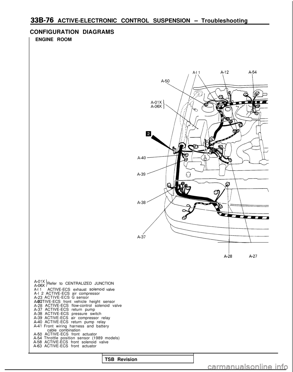
CONFIGURATION DIAGRAMS ENGINE ROOM
A-l 1 A-12 A-54
A-28
A-27
2:;. Refer to CENTRALIZED JUNCTIONIA-l 1ACTIVE-ECS exhaust solenoid valve
A-l 2 ACTIVE-ECS air compressor A-23
ACTIVE-ECS
G sensor A-27 ACTIVE-ECS front vehicle height sensor
A-28
ACTIVE-ECS flow-control solenoid valve A-37
ACTIVE-ECS return pump A-38
ACTIVE-ECS pressure switch A-39
ACTIVE-ECS air compressor relay
A40 ACTIVE-ECS return pump relayA-41 Front wiring harness and battery
cable combination A-50
ACTIVE-ECS front actuator A-54
Throttle position sensor (1989 models) A-58
ACTIVE-ECS front solenoid valve A-63
ACTIVE-ECS front actuator
TSB Revision
Page 1019 of 1273
33B-80 ACTIVE-ELECTRONIC CONTROL SUSPENSION - Troubleshooting
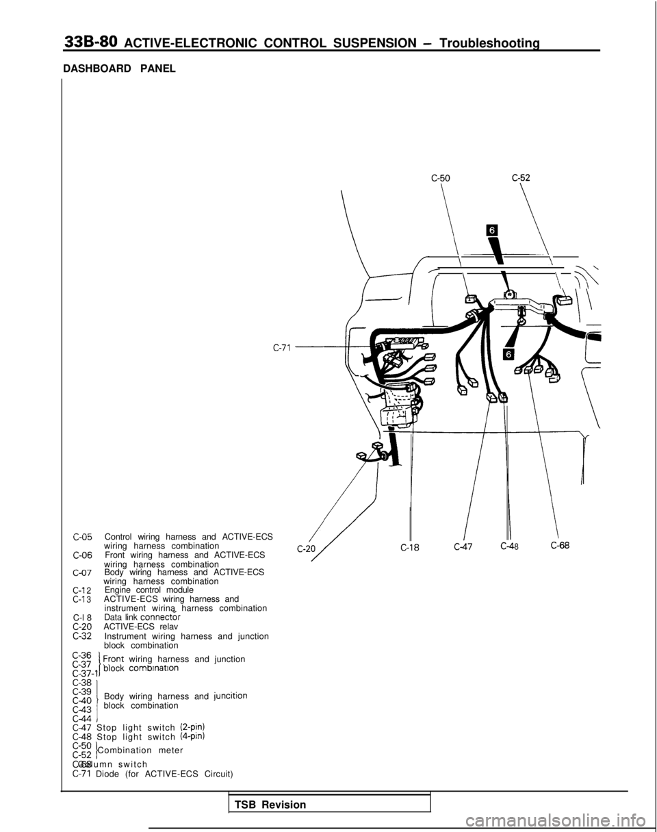
DASHBOARD PANEL
c-05 C-06
c-07
C-l
2
C-l 3
C-l 8c-20C-32
Control wiring harness and ACTIVE-ECS
wiring harness combination Front wiring harness and ACTIVE-ECS
wiring harness combination Body wiring harness and ACTIVE-ECS
wiring harness combination Engine control module
ACTIVE-ECS wiring harness and
instrument wirina harness combination
Data link
connect&ACTIVE-ECS relav
Instrument wiring harness and junction
block combination C-36
block
combrnatlon1 Front
wiring harness and junction
Body wiring harness and
juncitionblock combination
C-47 Stop light switch (2-pjn)rC&$ Stop light switch (4-pin)
c-52 Combination metert C-68 Column switch
C-71 Diode (for ACTIVE-ECS Circuit)
\\\/
/\\ ?b
c-71
-If8C-68
TSB Revision
Page 1022 of 1273
ACTIVE-ELECTRONIC CONTROL
SUSPENSION - Troubleshooting 33B-83
D-21
TSB RevisionI
>
\D-24 36A0185
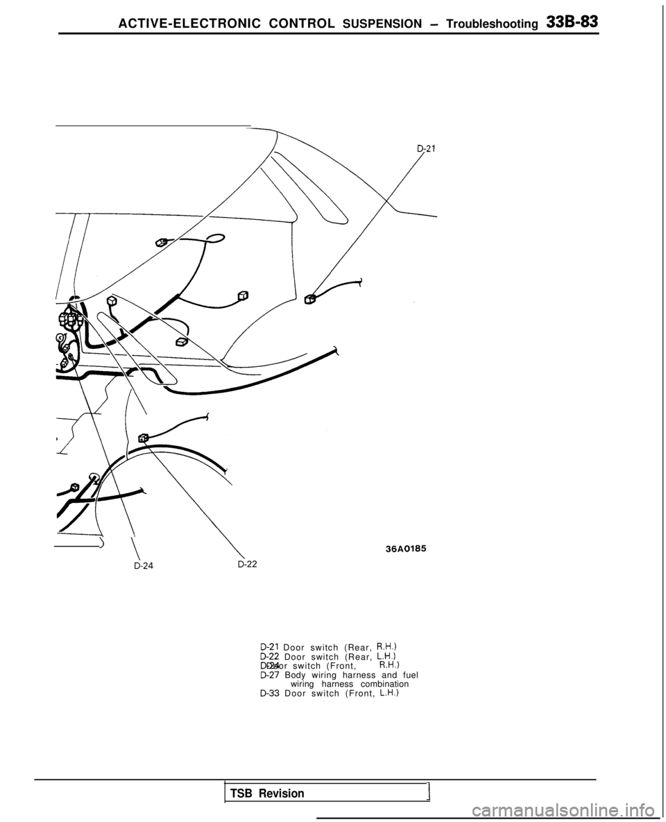
D-21 Door switch (Rear, R.H.)D-22 Door switch (Rear,
L.H.l
D-24 Door switch (Front, R.H.)D-27 Body wiring harness and fuel
wiring harness combination
D-33 Door switch (Front, L.H.)
Page 1024 of 1273
ACTIVE-ELECTRONIC CONTROL SUSPENSION - Troubleshooting 33B-85
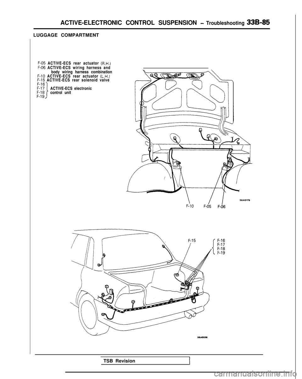
LUGGAGE COMPARTMENTF-05
ACTIVE-ECS rear actuator (R.H.)
F-06
ACTIVE-ECS wiring harness and
body wiring harness combination F-10
ACTIVE-ECS rear actuator (L.H.)
F-15
ACTIVE-ECS rear solenoid valve
ACTIVE-ECS electronic
control unit
\ F-101 IF-05
F-06
F-16
F-17
F-18
F-19
TSB Revision
1