1989 MITSUBISHI GALANT steering wheel
[x] Cancel search: steering wheelPage 249 of 1273
FUEL SYSTEM
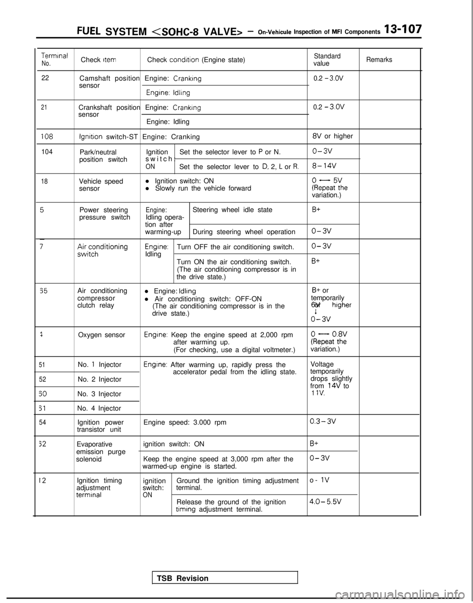
TerminalCheck ItemCheck condition
(Engine state)StandardNo.valueRemarks
22
Camshaft position Engine: Cranking0.2 - 3.ov
sensor
Engrne: ldllng
21Crankshaft position Engine: Crankingsensor
Engine: Idling0.2 - 3.ov
108
104
18
lgnrtron switch-ST Engine: Cranking 8V
or higher
Park/neutral Ignition
Set the selector lever to
P or N.o-3v
position switch switch
:
ONSet the selector lever to D, 2, L or R.8- 14V
Vehicle speed
l Ignition switch: ON
sensor l Slowly run the vehicle forwardkeFaF:hevariation.)
Power steering
pressure switch
;;ir;z;ditioning
Engine:Steering wheel idle state
Idling opera-
tion after
warming-up During steering wheel operation
Engrne:Turn OFF the air conditioning switch.
Idling
Turn ON the air conditioning switch.(The air conditioning compressor is in
the drive state.)
B+
o-3v
o-3v
B+
35
1
51
52
50
51
54
Air conditioning
compressor
clutch relay
Oxygen sensor
No.
1 Injector
No. 2 Injector
No. 3 Injector
No. 4 Injector Ignition power
transistor unit l Engine: Idling
B+ or
l Air conditioning switch: OFF-ON temporarily
(The air conditioning compressor is in the 6V or
higher
drive state.)o’- 3v
Engine: Keep the engine speed at 2,000 rpm
after warming up. kQatot8h2:
(For checking, use a digital voltmeter.) variation.)
Engine: After warming up, rapidly press the
Voltage
accelerator pedal from the idling state. temporarily
drops slightly
from
14V to1 IV.
Engine speed: 3.000 rpm0.3- 3v
Evaporative
emission purge
solenoid ignition switch: ON
Keep the engine speed at 3,000 rpm after the
warmed-up engine is started.B+
o-3v
12Ignition timing
adjustment terminal
ignition
Ground the ignition timing adjustment o- 1vswitch:
terminal.ONRelease the ground of the ignition4.0- 5.W timing
adjustment terminal.
TSB Revision
Page 276 of 1273
13-134FUEL SYSTEM (SOHC-16 VALVE> -Service Adjustment Procedures
BASIC IDLE SPEED ADJUSTMENTMlIFHBX
NOTE
1. The standard idling speed has been adjusted, by the en-
gine speed adjusting screw, by the manufacturer, and
there should usually be no need for readjustment.
2. Use the following procedure to adjust when the idling speed drops due to an incorrect adjustment, high idling
speed, or when a load such as the air conditioning is ap-
plied on the engine.
3. The adjustment, if made, should be made after first con- firming that the spark plugs, the injectors, the idle air con-
trol motor, the compression pressure, etc. are all normal.
(I ) The vehicle should be prepared as follows before the inspec- tion and adjustment.
l Engine coolant temperature:
85-95°C (185-203°F)
l Lights, cooling fan and accessories: OFF
l Transaxle: neutral (A/T for
P range)
l Steering wheel: neutral position
(2) Connect the scan tool to the data link connector (white).
NOTE
When the scan tool is connected, the diagnostic test mode control terminal should be grounded.
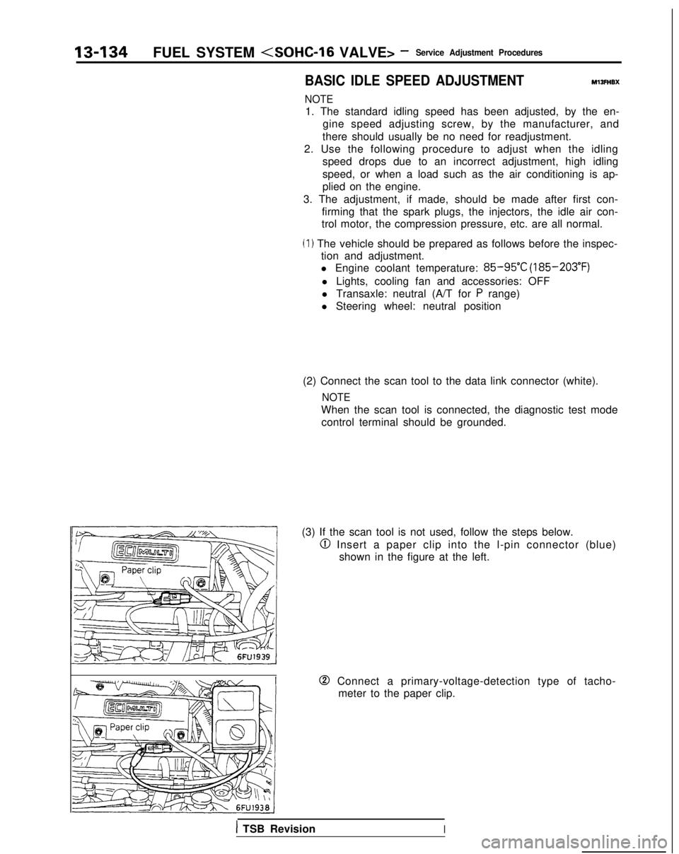
(3) If the scan tool is not used, follow the steps below.
@I Insert a paper clip into the l-pin connector (blue) shown in the figure at the left.
0 Connect a primary-voltage-detection type of tacho-meter to the paper clip.
1 TSB RevisionI
Page 335 of 1273
FUEL SYSTEM
TerminaNo.
19
52
-rII
i
t
c
65
L
63
64t
I:
I
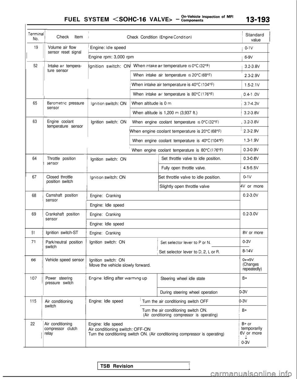
Check Item :Check Condition (Engrne Condrtron)
Volume air flowj Engine: Idle speedsensor reset signal
1
Engine rpm: 3,000 rpm
Intake air tempera-1Ignition switch: ON When Intake atr temperature IS 0°C (32°F)ture sensor
When intake air temperature IS 20°C (68°F)
i When intake air temperature is 40°C (104°F)
When intake air temperature is 80°C (176°F)
lgnltlon switch: ON’ When altitude is 0 m
When altitude is 1,200 m (3,937 ft.)
Ignition switch: ON
i When engine coolant temperature IS 0°C (32°F)
When engine coolant temperature is 20°C (68°F)
When engine coolant temperature is 40°C (104°F)
Barometnc pressuresensor
Engine coolant
temperature sensor
Throttle positionsensor
67
68
69
51
115
1
1
Ic22
Closed throttle
position switch
Camshaft position
sensor
Crankshaft position
sensor
Ignition switch-ST
Park/neutral position
switch
Vehicle speed sensor
Power steering
pressure switch
Air conditioning
switch
-I
I When engine coolant temperature is 80°C (176°F)
‘I
) 0.3-0.9v
Ignition switch: ON Set throttle valve to idle position.
0.3-0.6V
iFully open throttle valve.1 4.5-5.5v
Ignition switch: ON
Set throttle valve to idle position.o-1v
’ Slightly open throttle valve4V or more
Engine: Cranking0.2-3.OV
Engine: Idle speed
Engine: Cranking0.2-3.OV
Engine: Idle speed
Engine: Cranking8V or more
Ignition switch: ON
( SetselectorlevertoPorN.o-3v
i Set selector lever to D. 2, L or R.8-14V
Ignition switch: ONi 04d5v
Move the vehicle slowly forward.(Changesrepeatedly)
Engine. Idling after warmrng upSteering wheel idle stateB+
During steering wheel operationo-3v
Engine: Idle speed
’ Turn the air conditioning switch OFFo-3vI
’ Turn the air conditioning switch ON.1 B+(Air conditioning compressor is operating)!
Engine: Idle speed1 B+or
Air conditioning switch: OFF-ONI temporarily
Turn the conditioning switch ON. (Air conditioning compressor is operat\
ing) 1
6V or morej 1
1 o-3v
/ Standard
value
/ o-1v
1 6-9V
1 3.2-3.8V
: 2.3-2.9v
1.5-2.1V
i 0.4-I .ov
j 3.7-4.3v
/ 3.2-3.8V
, 3.2-3.8V
1, 2.3-2.9v
1.3-l .9vI
Air conditioningcompressor clutchrelay
TSB Revision1
Page 355 of 1273
FUEL SYSTEM
PROBLEM SYMPTOMS TABLE(FORYOUR
INFORMATION) Item
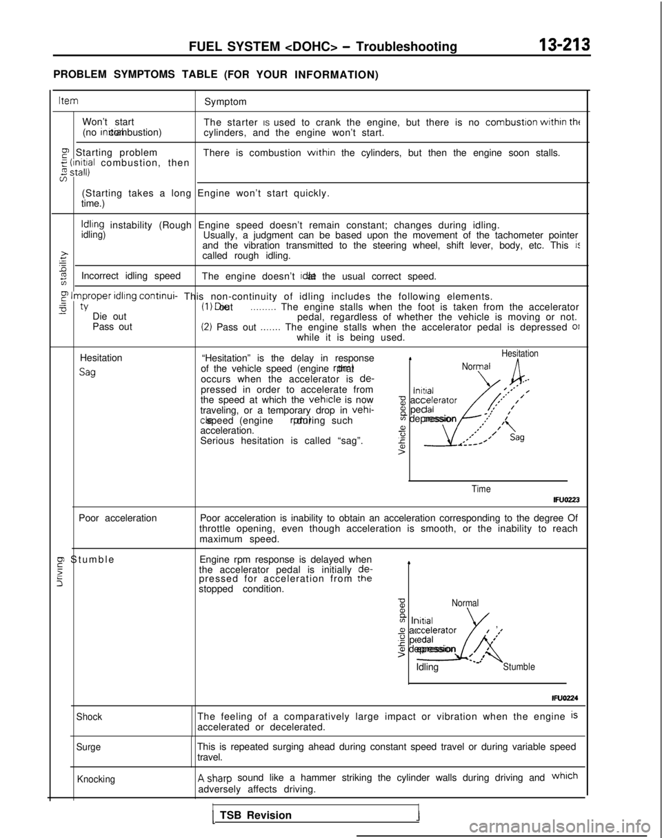
Symptom
Won’t start The starter IS used to crank the engine, but there is no combustron
withrn
tht(no inrtial combustion)
cylinders, and the engine won’t start.
p Starting problem There is combustion within the cylinders, but then the engine soon stalls.g
$$a combustion, then
5
(Starting takes a long Engine won’t start quickly.
time.)
Idling instability (Rough Engine speed doesn’t remain constant; changes du\
ring idling.idling)Usually, a judgment can be based upon the movement of the tachometer poi\
nter
and the vibration transmitted to the steering wheel, shift lever, body, \
etc. This i:>.ccalled rough idling.=
%zIncorrect idling speed The engine doesn’t Idle at the usual correct speed.
F
Improper
idling continui-
This non-continuity of idling includes the following elements.-0tY (I 1 Die out .._.__... The engine stalls when the foot is taken from the accelerator-Die out
pedal, regardless of whether the vehicle is moving or not.
Pass out(2) Pass out .._.... The engine stalls when the accelerator pedal is depressed 01while it is being used.
Hesitation
Sag
“Hesitation” is the delay in response1Hesitation
of the vehicle speed (engine rpm) thatNormal
occurs when the accelerator is
de-,--pressed in order to accelerate from\alnrtral-’‘** /the speed at which the vehicle is nowz accelerator,’ ’
traveling, or a temporary drop in vehi-8 pedal/*’
,’ ,’
cle speed (engine rpm) during such
acceleration. a
Serious hesitation is called “sag”.
4sAK
m depression .I’
1’
,’*;’ I(,
r-----
4’>
Time
IFUOZ23
Poor acceleration Poor acceleration is inability to obtain an acceleration corresponding t\
o the degree Of
throttle opening, even though acceleration is smooth, or the inability t\
o reach maximum speed.
F Stumbl
e
5
5
Engine rpm response is delayed when
the accelerator pedal is initially de-
pressed for acceleration from the
stopped condition.4
BNormal B
m Initiala acceleratorg pedal
I
’
-2
/#’
01 depression4t’>’ /Idling L’Stumble
IFUO224
ShockThe feeling of a comparatively large impact or vibration when the engine\
isaccelerated or decelerated.
SurgeThis is repeated surging ahead during constant speed travel or during va\
riable speed
travel.
KnockingA sharp sound like a hammer striking the cylinder walls during driving and which
adversely affects driving.
II1 TSB Revision1
Page 458 of 1273
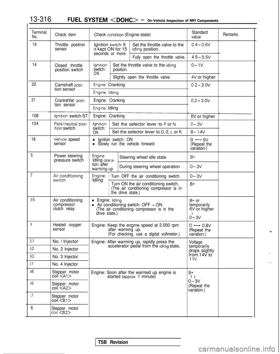
13-316FUEL SYSTEM
Inspection
of
MFI
Components
TerminalNo.Check itemCheck condition (Engine state)Standardvalue
Remarks
19Throttle positronIgnition switch: ItSet the throttle valve to the0.4- 0.wsensorIS kept ON for 15seconds or moreidlrng position.
Fully open the throttle valve.4.5- 5.5v
14
Closed throttlelgnrtrono-1vposition switchswitch:Set the throttle valve to the idling
position.
ONSlightly open the throttle valve.4V or higher
22Camshaft posi-tion sensorEngine: Cranking0.2- 3.ov
Engine: ldlrng
21
Crankshfat posi-tion sensor Engine: Cranking0.2- 3.ov
Engine: Idling
108lgnrtion switch-STEngine: Cranking8V or higher
104
Park/neutral
pos-ition switchIgnitionSet the selector lever to P or N.o-3vswitch:ONSet the selector lever to D, 2, L or R.8- 14V
18Vehicle speedl Ignition switch: ON
sensorl Slowly run the vehicle forward0 - 5v(Repeat the
variation.)
5Power steering
pressure switchEngine:Idling opera-Steering wheel idle stateB+
tion afterwarming-upDuring steering wheel operationo-3v
7A&;;;ditioningEngine:Idling _Turn OFF the air conditioning switch.o-3v
Turn ON the air conditioning switch.B+
(The air conditioning compressor is in
the drive state.)
35Air conditioningl Engine: IdlingB+ orcompressor
clutch relayl Air conditioning switch: OFF -, ON(The air conditioning compressor is in the
temporarily
drive state.)6V or higher o’-
3v
1Heated oxygen
sensorEngine: Keep the engrne speed at 2.000 rpmafter warming up.
(For checking, use a digital voltmeter.)ke;atoZivariation.)
51No. 1 InjectorEngine: After warming up, rapidly press the
52No. 2 Injector accelerator pedal from the idlrng state,Voltage
temporarily
drops slightly
30No. 3 Injectorfrom 14V to1 IV.
51No. 4 Injector
j8
Stepper motorcoil
i9
Stepper motor0%
coil
variation.)
‘7Stepper motorcoil
8Stepper motorco11
TSB Revision
Page 657 of 1273
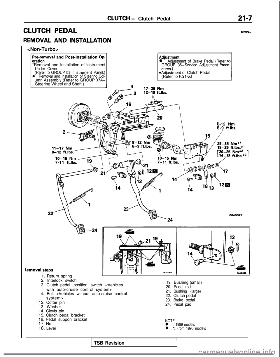
CLUTCH - Clutch Pedalm-7
CLUTCH PEDAL
REMOVAL AND INSTALLATION
Pre-removal and Post-installation Operation*Removal and Installation of InstrumentUnder Cover
(Refer to GROUP 52-Instrument Panel.)l Removal and Installation of Steering Col-umn Assembly (Refer to GROUP 37A-Steering Wheel and Shaft.)
Adjustmentl Adjustment of Brake Pedal (Refer tcGROUP 35-Service Adjustment Procedures.)@Adjustment of Clutch Pedal
(Refer to P.21-5.)
MZIPA-
2
8-12 Nm
6-9 ft.lbs.
r:-20-25Nmi12Lib-18ft.lbs.*21lo-15 Nm -7-11 ftlbs.
23
24
09AOO79
Semoval steps
1. Return spring
2. Interlock switch
3. Clutch pedal position switch
4. Bolt
12. Cotter pin
13. Washer
14. Clevis pin
15. Clutch pedal bracket
16. Pedal suppon bracket
17. Nut
18. Lever
19.Bushing (small)20. Pedal rod
21.
22. Bushing (large)
Clutch pedal23.
Brake pedal
24. Pedal pad
NOTEl ‘: 1989 modelsl *: From 1990 models
TSB Revision
Page 658 of 1273
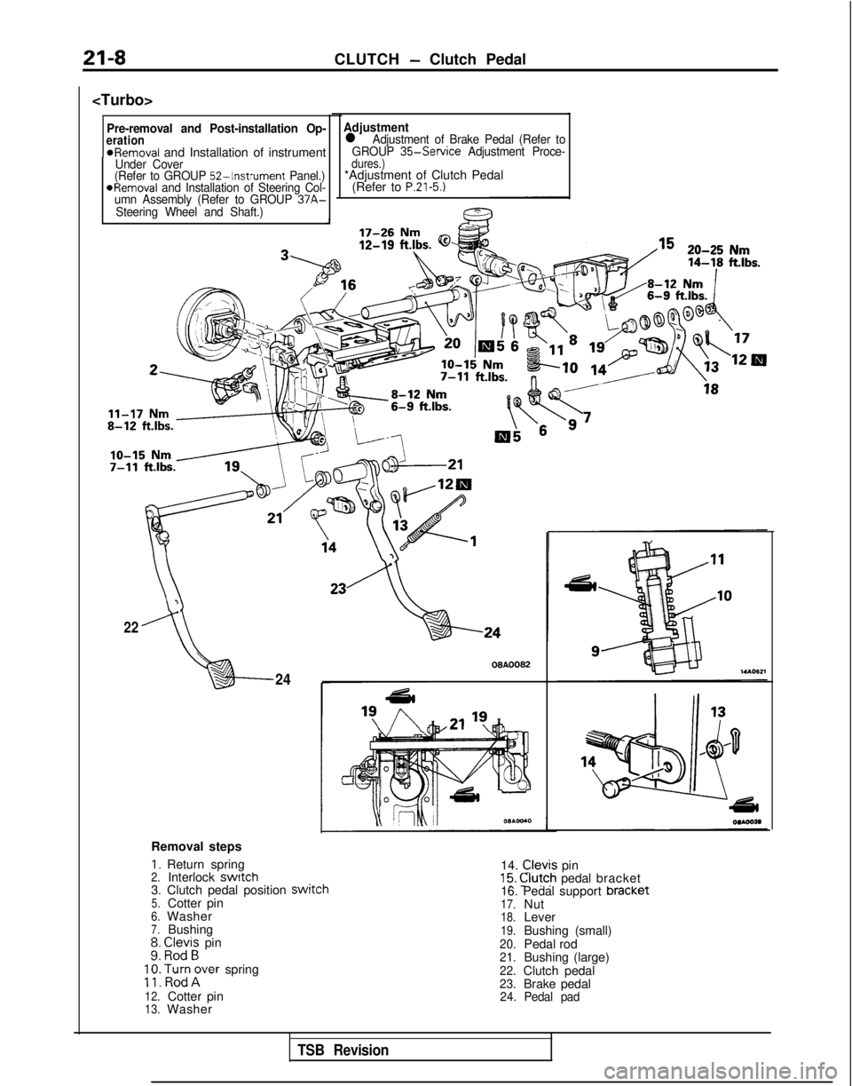
21-8CLUTCH- Clutch Pedal
Pre-removal and Post-installation Op-eration*Removal and Installation of instrumentUnder Cover
(Refer to GROUP 52-Instrument Panel.)*Removal and Installation of Steering Col-
umn Assembly (Refer to GROUP 37A-
Steering Wheel and Shaft.)
Adjustmentl Adjustment of Brake Pedal (Refer to
GROUP 35-Service Adjustment Proce-dures.)*Adjustment of Clutch Pedal
(Refer to P.21-5.1
3
22
“,24 00AOO82
Removal steps
I. Return spring 14. Clevis pin15. @fch pedal bracket2.Interlock switch3. Clutch pedal position switcn5.Cotter pin6.Washer7.Bushing;: E;;i; pin
;
;: poTrer spring
12.Cotter pin13.Washer 16. Pedal support bracket
17.Nut18.Lever19.Bushing (small)20.Pedal rod21.Bushing (large)22.Clutch pedal23.Brake pedal24.
Pedal pad
TSB Revision
Page 667 of 1273
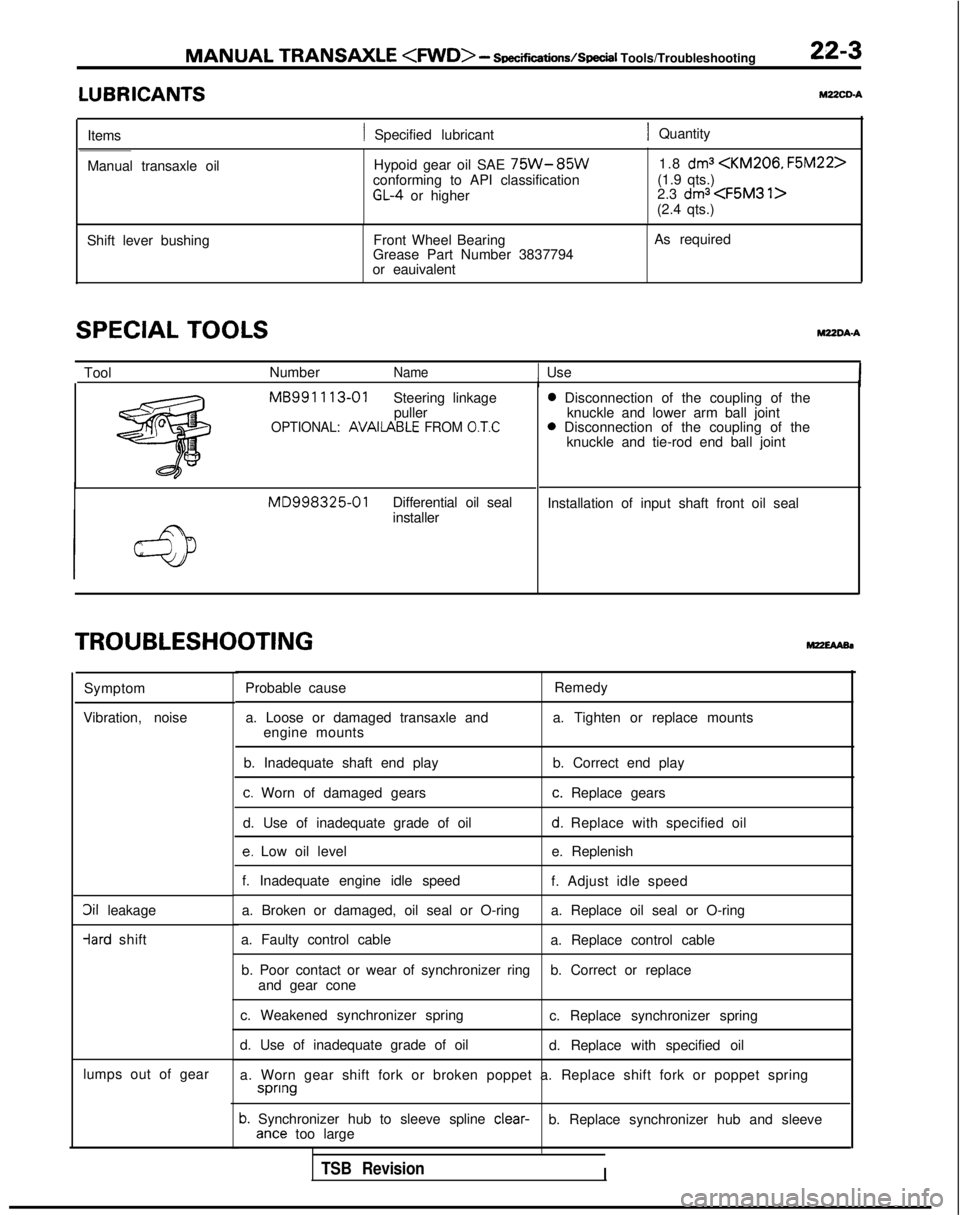
MANUAL TRANSAXLE
- Soec~cations/SpeciI
Tools/Troubleshooting 22-3
LUBRICANTSYZZCD-A
Items1 Specified lubricant1 Quantity
Manual transaxle oil Hypoid gear oil SAE
75W-85Wconforming to API classificationGL-4 or higher1.8
dma
(1.9 qts.)
2.3 dma
Shift lever bushing Front Wheel Bearing
Grease Part Number 3837794
or eauivalent As required
SPECIAL TOOLSWDA-A
Tool
NumberName1 UseI MB991
113-01
Steering linkage
puller
OPTIONAL: AVAIlABLE FROM 0.T.C
MD998325-01Differential oil seal
installer 0
Disconnection of the coupling of the
knuckle and lower arm ball joint 0
Disconnection of the coupling of the
knuckle and tie-rod end ball joint
Installation of input shaft front oil seal
TROUBLESHOOTING
Symptom
Vibration, noise
3il leakage -lard
shift
lumps out of gear Probable cause
Remedy
a. Loose or damaged transaxle and a. Tighten or replace mounts
engine mounts
b. Inadequate shaft end play b. Correct end play
c. Worn of damaged gearsc. Replace gears
d. Use of inadequate grade of oil
d. Replace with specified oil
e. Low oil level e. Replenish
f. Inadequate engine idle speed f. Adjust idle speed
a. Broken or damaged, oil seal or O-ring a. Replace oil seal or O-ring
a. Faulty control cable a. Replace control cable
b. Poor contact or wear of synchronizer ring b. Correct or replace
and gear cone
c. Weakened synchronizer spring c. Replace synchronizer spring
d. Use of inadequate grade of oil d. Replace with specified oil
a. Worn gear shift fork or broken poppet a. Replace shift fork or poppet\
spring spnng
b. Synchronizer hub to sleeve spline
clear-
b. Replace synchronizer hub and sleeveante too large
TSB RevisionI