1989 MITSUBISHI GALANT steering wheel
[x] Cancel search: steering wheelPage 1031 of 1273
33B-92 ACTIVE-ELECTRONIC CONTROL SUSPENSION - ~~:%:?stment
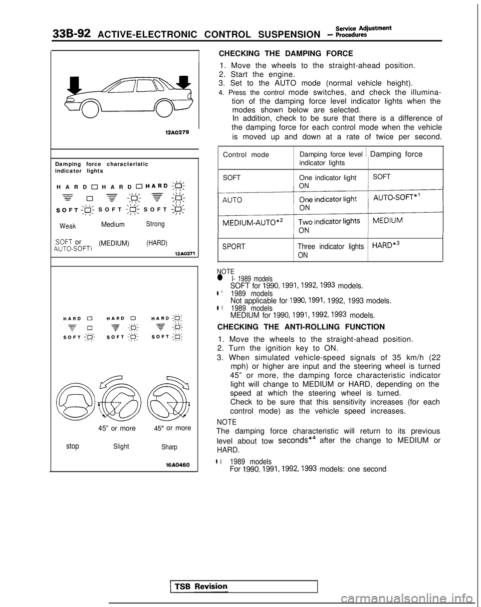
CHECKING THE DAMPING FORCE
12A0279
Damping force characteristic
indicator lights
,\,IHARD 0 HARD 0 HARD;g!;
=-\\I, =\\ l,=0 -=-,F; f;F:
SOFT ,gi SOFT
:SOFT or(MEDIUM)(HARD)4UTOSOFT)12AQ271
./I,HARD 0HARD 0HARD ;g;
z-0 -\k 3,\I I,SOFT ;p;SOFT ;R-SOFT I@;
45” or more45” or more
stopSlight
Sharp
16AQ460
1. Move the wheels to the straight-ahead position.
2. Start the engine.
3. Set to the AUTO mode (normal vehicle height).
4. Press the control mode switches, and check the illumina-
tion of the damping force level indicator lights when themodes shown below are selected.In addition, check to be sure that there is a difference of
the damping force for each control mode when the vehicle
is moved up and down at a rate of twice per second.
Control mode Damping force level
1 Damping force
indicator lights
SOFTOne indicator light
ON SOFT
SPORT
I
Three indicator lightsHARDe3
ON
NOTEl I- 1989 modelsSOFT for 1990,1991,1992,1993 models.l *:1989 modelsNot applicable for 1990,1991, 1992, 1993 models.l 3:1989 modelsMEDIUM for 1990,1991,1992,1993 models.
CHECKING THE ANTI-ROLLING FUNCTION
1. Move the wheels to the straight-ahead position.
2. Turn the ignition key to ON.
3. When simulated vehicle-speed signals of 35 km/h (22 mph) or higher are input and the steering wheel is turned
45” or more, the damping force characteristic indicator light will change to MEDIUM or HARD, depending on the
speed at which the steering wheel is turned. Check to be sure that this sensitivity increases (for each
control mode) as the vehicle speed increases.
NOTE
The damping force characteristic will return to its previous
level about tow seconds*4
after the change to MEDIUM or
HARD.
l 4:1989 modelsFor 1990,1991,1992,1993
models: one second
Page 1077 of 1273
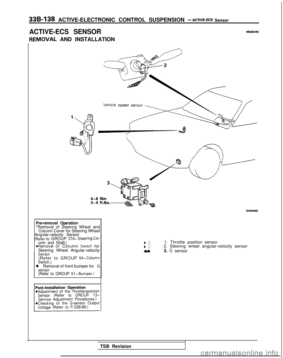
33B-138 ACTIVE-ELECTRONIC CONTROL SUSPENSION - ACTIVE-ECS Sensor
ACTIVE-ECS SENSORM33ZVAC
IEMOVAL
AND INSTALLATION
Pre-removal Operation*Removal of Steering Wheel and
Column Cover for Steering Wheel
Angular-velocity Sensor
(Referto GROUP 37A-Steering Cof-umn and Shaft.) ~
@Removal of Column Switch for
Steering Wheel Angular-velocity
Sensor-(Refer to GROUP 54-ColumnSwitch.)l Removal of front bumper forGsensor(Refer to GROUP 51-Bumper.)
1210449
l *1. Throttle position sensor
l *2. Steering wheel angular-velocity sensor
4*3. G sensor
TSB Revision
Page 1078 of 1273
ACTIVE-ELECTRONIC CONTROL SUSPENSION - ACTIVE-
ECS Sensor 33B-139
Steering wheel angular-velocity sensor
TSB Revision--
12A046
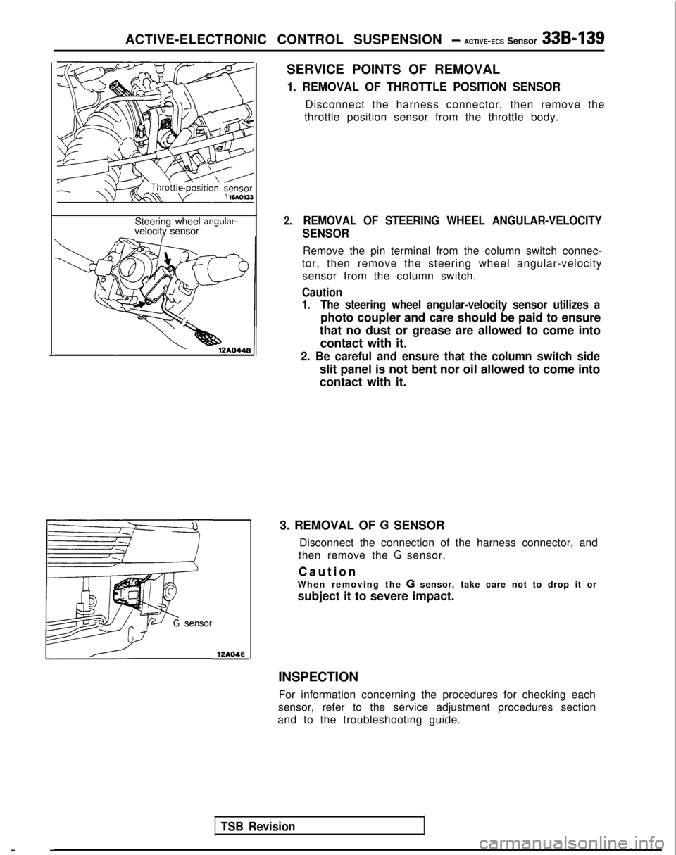
SERVICE POINTS OF REMOVAL
1. REMOVAL OF THROTTLE POSITION SENSOR
Disconnect the harness connector, then remove the
throttle position sensor from the throttle body.
2.REMOVAL OF STEERING WHEEL ANGULAR-VELOCITY
SENSOR
Remove the pin terminal from the column switch connec-
tor, then remove the steering wheel angular-velocity sensor from the column switch.
Caution
1.The steering wheel angular-velocity sensor utilizes a
photo coupler and care should be paid to ensure
that no dust or grease are allowed to come into contact with it.
2. Be careful and ensure that the column switch side
slit panel is not bent nor oil allowed to come into
contact with it.
3. REMOVAL OF
G SENSOR
Disconnect the connection of the harness connector, and
then remove the
G sensor.
Cautio
n
When removing the
G sensor, take care not to drop it or
subject it to severe impact.
INSPECTION For information concerning the procedures for checking each
sensor, refer to the service adjustment procedures section
and to the troubleshooting guide.
Page 1136 of 1273
SERVICE BRAKES - Anti-lock Braking System Troubleshooting35-15
ANTI-LOCK BRAKING SYSTEM
TROUBLESHOOTINGM35EElAE
PARTICULAR CHARACTERISTICS OF
THE ANTI-LOCK BRAKING SYSTEM
Models equipped with the anti-lock braking system
(A.B.S.) may exhibit one or more of the following
characteristics from time to time, but none of these
is abnormal.
(1)
(2)
A pulsing feeling in the brake pedal, or vibration
of the body or the steering wheel, when the
anti-lock braking system is activated by sudden
braking or by braking on a slippery road surface.
Actually, this phenomenon is an indication that
the anti-lock braking system is functioning nor-
mally.
When the vehicle speed reaches approximately
6 km/h (4 mph) after the engine is started and
the vehicle starts off (for the first time), awhining motor noise may be heard from the
engine compartment if the vehicle is traveling in
a quiet place. This noise is simply the result of a
self-check being made of the anti-lock braking
system operation.
TROUBLESHOOTING METHODS
Problems related to the anti-lock braking system
(A.B.S.) can be classified into two general categor-
ies: problems in the electrical system and those in
the hydraulic system. For problems in the electrical system, the on-board
diagnostic is built into the electronic control unit
(E.C.U.) causing the A.B.S. warning light to illuminate
as a warning to the driver. In this instance, checks
can be made by using the scan tool and oscillo-
scope.
Problems in the hydraulic system (poor braking,
etc.) can be located in the same way as for ordinary
brakes. There is, however, the necessity to check to
determine whether the problem is related to ordi-
nary brake components or to the components re-
lated to the A.B.S. To make this check, use the scan
tool.
HOW TO USE THE TROUBLESHOOTING
FLOW CHART
(1) Using the flow chart, check the ABS warning
light light-up sequence. Read the diagnostic
trouble codes and check the condition of bra-
king operation.
(2) Following the check chart listed in the remedy
column, perform the checks. There are [Expla- nation] and [Hint] in each check chart. Refer to
them when troubleshooting.
NOTE
ECU: Electronic control unit
HU:Hydraulic unit
TSB Revision
Page 1197 of 1273
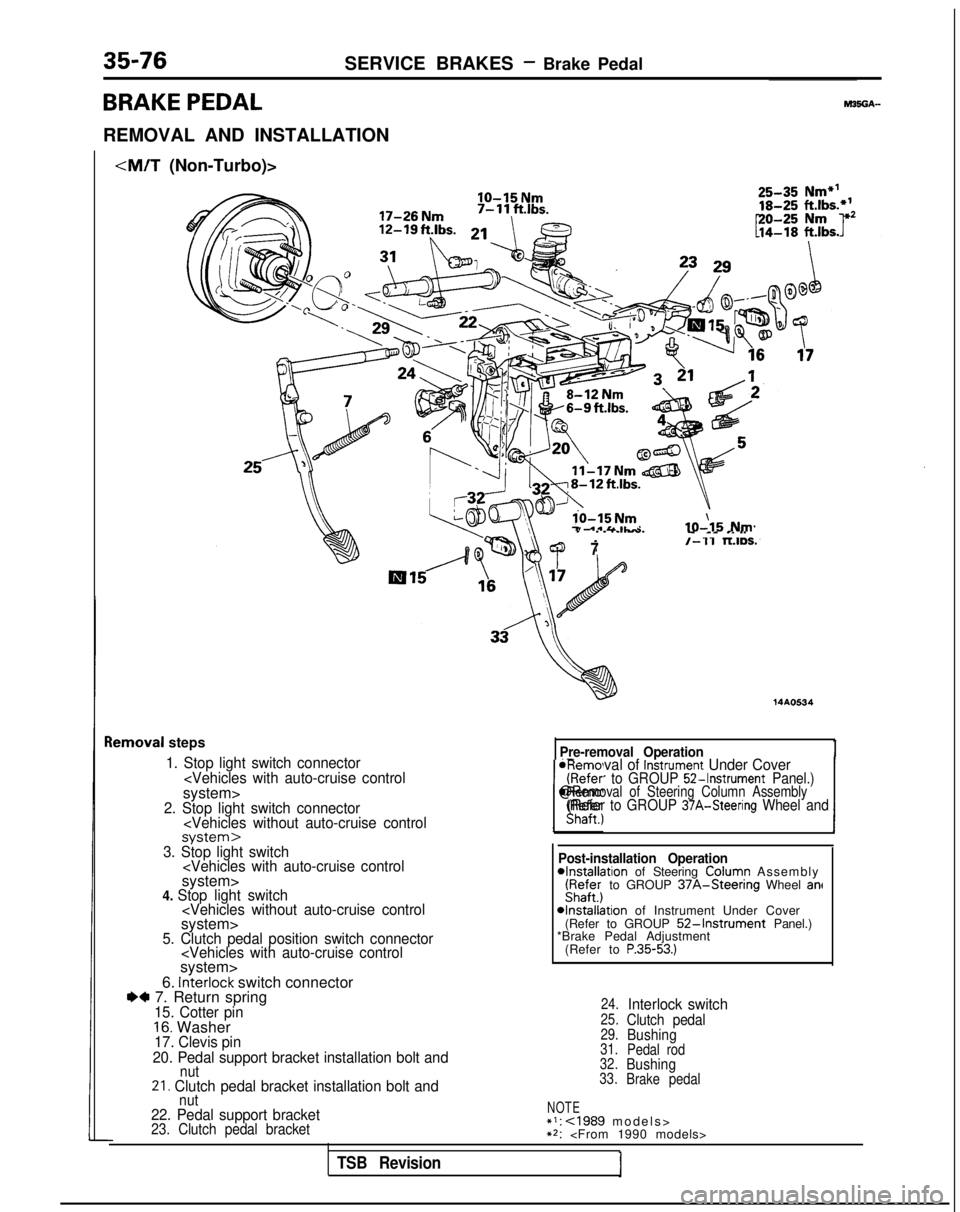
35-76SERVICE BRAKES - Brake Pedal
BRAKE PEDAL
REMOVAL AND INSTALLATION
IO-15 Nm
lo-15 Nm7 .*&&IL-IO-\15 Nm
lemoval
steps
1. Stop light switch connector
7/-11 TLIDS.
14AO534
Pre-removal Operation
*Removal of Instrument Under Cover(Refer to GROUP 52-Instrument Panel.)
IShaft., 1
@Removal of Steering Column Assembly(Refer to GROUP 37A-Steering Wheel and
-I---.3. Stop light switch
6. interlock switch connectorI)* 7. Return spring15. Cotter pin16. Washer17. Clevis pin
20. Pedal support bracket installation bolt and
nut21. Clutch pedal bracket installation bolt and Post-installation Operation
4nstallation of Steering ColuFn Assembl
y
iyafe;j to GROUP 37A-Steenng Wheel ant
4nstallation of Instrument Under Cover
(Refer to GROUP 52-Instrument Panel.)
*Brake Pedal Adjustment
(Refer to
P.35-53.)
24.Interlock switch25.Clutch pedal29.Bushing31. Pedal rod
32.Bushing33. Brake pedal
nut22. Pedal support bracketNOTE*I: cl989 models
>
23. Clutch pedal bracket**:
TSB Revision
Page 1198 of 1273
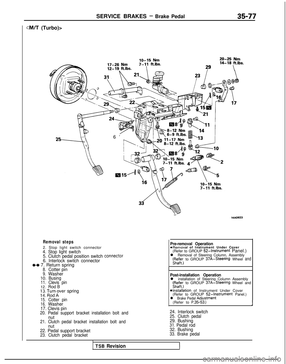
SERVICE BRAKES - Brake Pedal35-77
:M/T (Turbo)>
lo-15 Nm20-25 Nm
17-26 Nm7-11
ftlbs. 14-18
ft.lbs.
12-19. ft.lbs.I?9\ a-
6’
Removal steps
2. Stop light switch connector4. Stop light switch
5. Clutch pedal position switch connector
6. Interlock switch connectorI)+ 7. Return spring8.Cotter pin9.Washer10.Busing11.Clevis pin12.RodB; 2: ‘,l%;rer spring
15.Cotter pin16.Washer
17. Clevis pin
20. Pedal support bracket installation bolt andnut21. Clutch pedal bracket installation bolt andnut
22. Pedal support bracket
23. Clutch pedal bracket
- 14AO623
Pre-removal Operation
*Removal
of Instrument Under Cover
(Refer to GROUP
52-Instrument Panel.)
l Removal of Steering Column, Assembly r;affer)
to GROUP
37A-Steenng Wheeland
I
Post-installation Operationl installation of Steering Column Assembly(Fyaffer) to GROUP 37A-Steenng Wheel and
*Installation of Instrument Under Cover
(Refer to GROUP 52-Instrument Panel.)l Brake Pedal Adiustment
(Refer to P.35-53.)1
24. Interlock switch25. Clutch pedal29. Bushing31. Pedal rod
32. Bushing
33. Brake pedal
TSB RevisionI
Page 1262 of 1273
ALPHABETICAL INDEX1
A
ABS
Checking by the ABS Warnrng Light................
. 35-68-l
Troubleshooting ...........................
35-l 5-l
ABS POWER RELAY, Chec
k 35-74-l
ACCELERATOR CABLE
Inspection and Adjustment
13-398-l
Inspection and Adjustment
ACCELERATOR SWITCH, Inspection and Adjustment 13-329-I
A/C COMPRESSOR CLUTCH RELAY
On-vehicle Inspection
.............
. 13-285-l
On-vehrcle
Inspection
. 13-83-t
On-vehicle Inspection
. 13-176-l
ACTIVE-ECS ON-BOARD DIAGNOSTIC, Check......
. 338-88-I
ACTIVE-ECS RELAY.......................
. 338-141
-I
ACTIVE-ECS SENSOR....
.
...... ............ 338-138-I
ACTIVE-ECS SYSTEM
Checking by Using Alarm Light
.................
. 338-87-I
Operation Check ........................... 338-90-I
AERO PARTS..
.
........................... 51-18-l
AIR CLEANER...............................
. 15-9-I
AIR CLEANER ELEMENT
Inspection and Replacement
....................
. 15-6-l
Maintenance .......................... 00-39-l
AIR COMPRESSOR..........................
. 338-125-I
AIR CONDITIONING SWITCH
Emission control
...........................
.
17-21 -I
Heater, Air
Conditionrng
and Ventilation .............. 55-29-l
On-vehicle Inspection
On-vehicle Inspection
. 13-83-l
On-vehicle Inspection
. 13-176-l
AIR TUBE..............
.
....................... 338-133-I
ALARM LIGHT, Check. ......................... 338-87-I
ALARM SYSTEM, Theft ..........................
54-165-11
ALIGNMENT
Front Wheel, Adjustment .......................
. 33A-5-l
Rear
Wheel, inspection
. 34-23-l
Rear Wheel, Inspection
. 34-5-l
ANTENNA ......................................
54-153-11
ANTI-LOCK BRAKING SYSTEM, Troubleshooting .........
.
35-15-1
ARM
Lower
. 338-103-I
Lower
.
33A-10-I
Lower
................... 34-28-l
Torsion
.
338-l 19-l
Torsion
...................34-l 5-lTrailing
................. 34-31-l
Upper
.................. 34-28-l
AUDIO
SYSTEM................
.
.................
54-l 12-11
AUTO-CRUISE CONTROL. ..........................
. 13-408-I
AUTO-CRUISE CONTROL INDIVIDUAL PARTS, inspection..
. 13-401-I
AUTO-CRUISE CONTROL SYSTEM...................
. 13-332-l
AUTO-CRUISE CONTROL SYSTEM, Inspection..........
. 13-397-l
AUTOMATIC TRANSAXLE, Maintenance ................. 00-43-I
AXLE
Rear, Maintenance
...............................
. 00-45-I
Torsion
.
338-l 19-l
Torsion
.
......................... 34-15-l
AXLE HUB
Rear
Rear CFWD-Rear
Drum Brakes> ................... 27-6-l
AXLE SHAFT
.
27-17-1
B
BACKLASH. Total, Rear Axle, Check
. 27-15-l
BALL JOINT
Rotation Starting Torque Check ...................... 378-8-I
Tie Rod End, Staning Torque Check .................. 37A-15-l
Tie Rod End, Variation Check ....................... 37A-15-l
BALL JOINT SEALS, Maintenance ..................... 00-45-I
BAR
Stabilizer
. 338-106-I
Stabilizer
. 33A-13-l
Stabilizer
. 34-37-l
BAROMETRIC PRESSURE SENSOR
On-vehicle Inspection
................
. 13-266-l
On-vehicle Inspection
On-vehicle Inspection
. 13-154-l
BASIC IDLE SPEED
Adjustment
...........................
. 13-245-l
Adjustment
Adjustment
. 13-133-l
BATTERY.........................................
.
54-2-11
BATTERY, Flat Remedy.
.............................
. 35-75-l
BEARING
Wheel, Adjustment
. 338-87-I
Wheel, Adjustment
BELT
Drive, Compressor, Adjustment
....................
. 55-17-l
Drive (For Water Pump and Generator), Maintenance ..... 00-41-I
Drive, Tension Adjustment
Drive, Tension Adjustment
Seat..........................................
. 52-39-l
Timing
Timing
. 11-34-l
Timing, Maintenance ............................... 00-40-I
Timing, Tension Adjustment
BLEEDING
Clutch
..........................................
. 21-6-l
4ws...........................................
. 370-4-I
Service Brakes. .................................. 35-57-l
Steering ........................................ 37A-22-l
BLOWER..........................................
. 55-32-l
BOOSTER
Brake
.........................................
. 35-85-l
Brake, Operating Inspection ......................... 35-54-l
BOOST METER, On-vehicle Inspection
BOOTS, Drive Shaft, Maintenance ....................... 00-45-I
BRAKE
Disc, Front
......................................
. 35-94-l
Disc, Rear.....................................
.
35-l 14-l
BRAKE BOOSTER
...................................
. 35-85-l
BRAKE BOOSTER, Operating Inspection .................. 35-54-l
BRAKE DISC
Front, Run-out Check.
.............................
. 35-63-l
Front, Run-out Correction ........................... 35-64-l
Front, Thickness Check ............................. 35-65-l
Rear, Run-out Check ............................... 35-66-l
Rear, Run-out Correction. ........................... 35-66-l
Rear, Thickness Check............................
. 35-66-l
BRAKE DRUM, tnside
Diameter, Check ................... 35-67-l
BRAKE FLUID LEVEL SENSOR, Check...................
. 35-54-l
BRAKE FLUID PRESSURE SWITCH
AWD-ABS (Up to 1991 Models)
....................
.
35-133-l
AWD-ABS
(Up to 1991 models), Check ...............
. 35-75-l
BRAKE HOSES, Maintenance ........................... 06-45-t
BRAKELINE
........................................
35-87-l
Page 1265 of 1273
4ALPHABETICAL INDEX
DOHC-Turbo.................................
. 15-31-f
SOHC-8VALVE..................................
.
15-27-t
SOHC-1 GVALVE............................
.
15-28-l
EXHAUST PIPEDOH
C
......................... 15-33-I
SOHC.....................................
.
15-32-l
EXHAUST SYSTEM, Maintenance ..................... 00-45-I
F
FAN MOTOR
Condenser
.............................
.
55-48-l
Radiator...................
.
......... 14-12-I
FEEDER CABLE ..........................
54-l 55-11FENDER................................
.
42-61-t
FILLER DOOR, Fuel Tank.........................
.
42-60-I
FILLER TUBE CAP, Fuel Tank, Inspection...............
.
17-21 -I
FILTER
Engine 011. Maintenance ....................
. 00-41-I
Fuel
Fuel
.
...................
13-I 15-lFuel
.
13-195
FITTINGS, Handling................................
. 55-22-l
FIXED SAS
Adjustment
........................
.
13-250-I
Adjustment
.
13-138-I
FLAT BATTERY, Remedy............................
.
35-75-l
FLOOR CONSOLE................................
.
52-29-l
FLUID
Power Steering, Level Check
...................
. 37A-21-l
Power Steering, Replacement ................. 37A-21-l
Transaxle, Replacement ..................... 23-82-l
FLUID LEVEL, Transaxle, Inspection .................. 23-82-l
FOG LIGHT................
.
......................
54-94-11FOG LIGHT SWITCH................................
.
54-99-114WS, Function Check
..........................
. 37B-6-l
FRONT BRAKE DISC
Run-out Check
...................................
. 35-63-I
Run-out Correction ........................... 35-64-l
Thickness Check .............................. 35-65-l
FRONT DISC BRAKE.................................
. 35-94-l
FRONT DISC BRAKE PAD, Check and Replacement ......... 35-59-l
FRONT DOOR DRIP LINE WEATHERSTRIP 42-112-I
FRONT DOOR GLASS...............................
. 42-80-l
FRONT DOOR HANDLE.........................
. 42-96-l
FRONT DOOR LATCH...
.
......... .......... 42-96-l
FRONT DOOR
MOULDING
........................... 42-112-I
FRONT DOOR REGULATOR........................
. 42-80-I
FRONT DOOR TRIM.................................
. 42-76-l
FRONT DOOR WATERPROOF FILM....................
. 42-76-l
FRONT GRILLE..................................
. 51-12-l
FRONT SEAT,...................................
. 52-35-l
FRONT WHEEL ALIGNMENT Adjustment
. 338-86-I
Adjustment
FUEL FILTER
DOHC
.......................................
. 13-327-I
SOHC-8VALVE
.................................
13-l 15-l SOHC-IGVALVE
................................ 13-195-I
FUEL HOSES, Maintenance ............................
00-39-1
FUEL LINE
DOHC-AWD ..................................
.
13-326-l
DOHC-FWD....................................
.
13-324-l
SOHC-8VALVE
................................. 13-113-l
SOHC-1 ~VALVE............................
.
13-l 95-IFUEL PRESSURE
On-vehicle Inspection
On-vehicle Inspection
On-vehicle Inspection
FUEL PRESSURE SOLENOID
On-vehicle Inspection
FUEL PUMP
On-vehicle Inspection
On-vehicle Inspection
On-vehicle Inspection
FUEL SYSTEM, Maintenanc
e
FUEL TANK
DOHC-AWD .,.......
DOHC-FW
D
SOHC-8VALVE
SOHC-16VALVE
FUEL TANK FILLER DOO
R
FUEL TANK FILLER TUBE CAP, Inspection
FUEL TANK PRESSURE CONTROL VALVE. 13-312-l
13-102-I
,.....13-I
92-l
13-307-I
......
13-258-l
....... 13-46-l
...... 13-147-l
....... 00-39-l
......
13-322-l
...... 13-318-l
..... 13-109-I
...... 13-195-I
....... 42-60-I
....... 17-21-I
....... 17-21-l
G
GARNISHES
51-13-l
GASKET
Cylinder Head
Cylinder Head
GAUGE UNIT, Engine Coolant Temperature
14-31-l
GEAR BOX, Power Steering 37A-32-l
GEAR OIL, Level Check
GENERATOR
16-g-11
GLASS
Door, Adjustmen
t
42-52-l
Door, Front 42-80-I
Door, Rear 42-83-l
Quarter Window 42-70-I
Window.............
.._......_...... 42-63-i
Window,Rear
42-72-i
GRILLE,Front
_. _. _.
51-12-l
G-SENSOR
Service Brakes
35-132-l
Output Voltage, Check 336-96-l
H
HANDLE
Door, Front
..........................
.
Door,Rear
...........................
Door Inside, Play Check. ..................
HAZARD SWITCH.........................
.
HEADLIGHTS............................
.
HEADLINING.............................
.
HEATED OXYGEN SENSOR, On-vehicle Inspection
>
...............................
HEATER CONTROL.......................
.
HEATER UNIT............................
.
HEIGHT SENSOR.........................
.
HIGH MOUNTED STOP LIGHT...............
.
42-96-1 42-99-l
42-52-l
54-98-11
54-92-11
52-31-l
13-290-I
55-25-l
55-30-I
338-l
35-l
54-96-11HIGH PRESSURE SWITCH (HIGH-PRESSURE TANK SIDE),Actuation Pressure Check. 338-94-I
16-42-11
42-55-l
42-50-I
54-l 03-11
54-105-11
HIGH TENSION CABLE, Spark Test
HOOD .__...._..._......__._...................
HOOD, Alignment Adjustment .
HOR
N
. . . . . . . . . . . . . . . . . . . . . . . . . . . . . . . . . . . . \
. . . HORNRELAY
._.._._....___.........__.._._..___
HOSE
Brake, Maintenance
.
00-45-I