1989 MITSUBISHI GALANT steering wheel
[x] Cancel search: steering wheelPage 835 of 1273
FRONT AXLE - Troubleshooting/Service Adjustment Procedures26-5
TROUBLESHOOTINGm6E6AA
Symptom
Vehicle pulls to one side Probable cause
Seizure of drive shaft ball joint
Abnormal wear, play or seizure of wheel bear-
ing
Remedy
Replace
Replace
Vibration
Shimmy Excessive noise Malfunction of front suspension or steering
Bend, damage or abnormal wear of drive shaft
Play in drive shaft and hub serration
Abnormal wear, play or seizure of wheel bear-
ing
Improper wheel alignment
Malfunction of front suspension or steering
Broken boot, grease leakage
Bend, damage or abnormal wear of drive shaft
Play of drive shaft and hub serration
Abnormal wear, play or seizure of center bearing Adjust or replace
Replace
Replace
Replace
Adjust or replace
Adjust or replace
Replace, repack grease
Replace
Replace
Replace
Abnormal wear, play or seizure of wheel bear-ing
Loose wheel nut
Malfunction of front suspension and steering
Replace
Retighten
Adjust or replace
SERVICE ADJUSTMENT
PROCEDURES
HUB END PLAY INSPECTIONM26FAAB
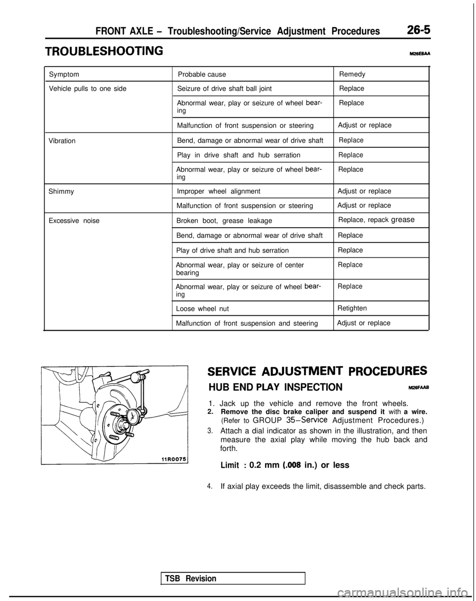
1. Jack up the vehicle and remove the front wheels.
2. Remove the disc brake caliper and suspend it with a wire.
(Refer to GROUP
35-Service Adjustment Procedures.)
3.Attach a dial indicator as shown in the illustration, and then measure the axial play while moving the hub back and
forth.
Limit: 0.2 mm (.008 in.) or less
4.If axial play exceeds the limit, disassemble and check parts.
TSB Revision
Page 913 of 1273
32-8POWER PLANT MOUNT -Centermember and Crossmember
CENTERMEMBER ANDCROSSMEMBER
REMOVAL AND INSTALLATIONM3ZYA-A
Pre-removal Operationl Disconnection of the Front Exhaust Pipe
when removing the Crossmember (Re-fer to GROUP 15-Exhaust Pipe and
Main Muffler.) aRaise
and Suspend the Engine to the
Extent Force IS not applied to the Engine
Mount
@Draining of the Power-steering Fluid (Re-
fer to GROUP 37A-Service Adjustment
Procedures.)
40-50 N29-36 ft
Post-installation Operationl Lower the Engine*Coupling of the Front Exhaust Pipe (Re-fer to GROUP 15-Exhaust Pipe and
Main Muffler.)
l Air bleeding of the Power-steering Fluid
(Refer to GROUP
37A- Service Adjust-
ment Procedures.)
l Adjustment of the Front Wheel Align-
ment
(Refer to GROUP
33A-Service Adjust-Iment Procedures.)
80-100 Nm
58-72 ft.lbs.
80-100 Nm
58-72 ft.lbs.
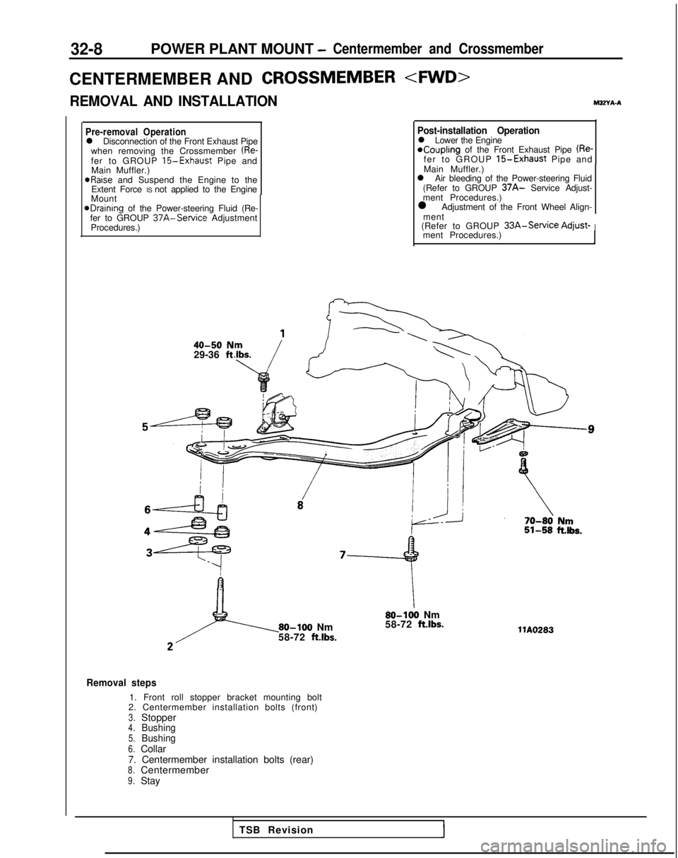
Removal steps
1. Front roll stopper bracket mounting bolt
2. Centermember installation bolts (front)
3.Stopper4.Bushing5.Bushing6.Collar
7. Centermember installation bolts (rear)
8.Centermember9.Stay llA0283
TSB Revision
Page 917 of 1273
32-12POWER PLANT MOUNT -Centermember and Crossmember
C&Et;;rSM>EMBER AND CROSSMEMBER
40-50 Nm29-36 ft.lbs.
50-65 Nm36-47 ft.lbs.80-100
Nm58-72 ftlbs.
80-100
Nm58-72 ft.lbs.
1
’
--
--_ii-58 it.,tTlAO619I 70-r
80 km51-58klbs.
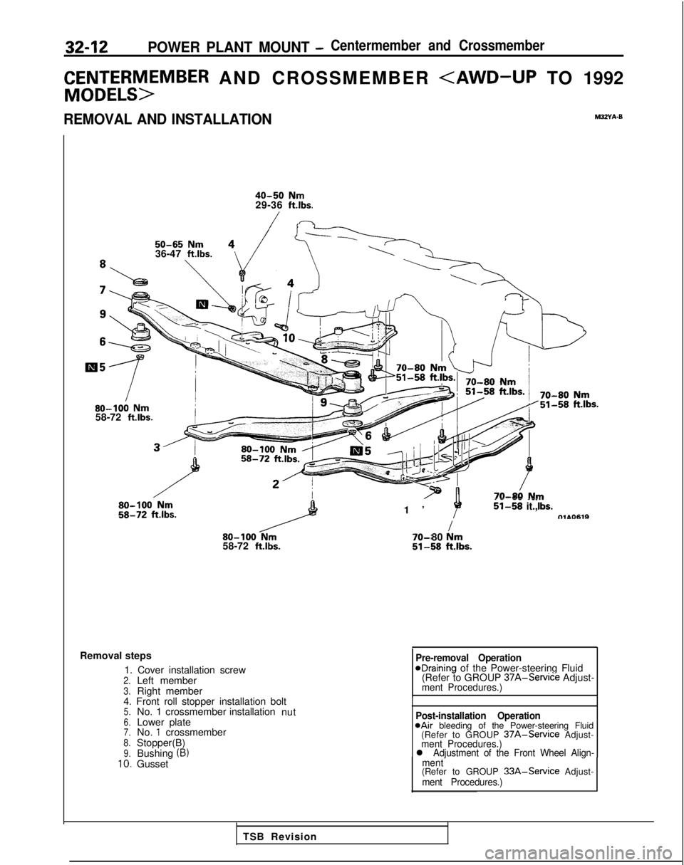
Removal steps
1. Cover installation screw
2.Left member3.Right member
4. Front roll stopper installation bolt
5.No. 1 crossmember installation
nut6.Lower plate7.No. 1 crossmember8.Stopper(B)9.Bushing (B)10.Gusset
Pre-removal OperationeDraining of the Power-steering Fluid
(Refer to GROUP 37A-Service
Adjust-
ment Procedures.)
Post-installation Operation@Air bleeding of the Power-steering Fluid
(Refer to GROUP 37A-Service Adjust-ment Procedures.)l Adjustment of the Front Wheel Align-
ment
(Refer to GROUP 33A-Service Adjust-ment Procedures.)
TSB Revision
Page 922 of 1273

33A-1
FRONT
SUSPENSION
CONTENTSMx(AA-
LOWERARM. . . . . . . . . . . . . . . . . . . . . . . . . . . . . . . . . . . . \
. . . . . . . . . . . . . . .10
SERVICE ADJUSTMENT PROCEDURES . . . . . . .5
Front Wheel Alignment . . . .._..__._...______..__.......5
WheelBearing Adjustment . . . . . . .5
SPECIAL TOOLS. . . . . . . . . . . . . . . . . . . . . . . . . . . . . . . . . . . . \
. . . . . . . . .4
SPECIFICATIONS
. . . . . . . . . . . . . . . . . . . . . . . . . . . . . . . . . . . . \
. . . . . . . . .2
GeneralSpecifications2. . . . . . . . . . . . . . . . . . . . . . . . . . . . . . . . .
Service Specifications . . . . . . . . . . . . . .3
Torque Specifications .._...._.__.....___..............,. 3
STABILIZER BAR. . . . . . . . . . . . . . . . . . . . . . . . . . . . . . . . . . . . \
. . . . . . . . .13
STRUT ASSEMBLY. . . . . . . . . . . . . . . . . . . . . . . . . . . . . . . . . . . . \
. . . . .6
4TROUBLESHOOTING. . . . . . . . . . . . . . . . . . . . . . . . . . . . . . . . . . . . \
. .
Excessive Vehicle Rolling
Inclination of Vehicle
Noise
Poor Riding
Steering Wheel is Heavy, Vibrates
or Pulls to One Side
Page 926 of 1273
FRONT SUSPENSION - Service Adiustment Procedures33A-5
eI
-a,
-
\ ~,I 1, 1
FY
TSB Revision
SERVICE ADJUSTMENT PROCEDURES
FRONT WHEEL ALIGNMENTM33FBAQ
NOTE
The front suspension assembly must be free of worn, loose or
damaged parts prior to measurement of front wheel align- ments. Measure wheel alignment by using the tool.
CAMBER AND CASTER
Standard value:
Camber22’ f 30’ 31’& 30
Caster2”f301”56’rtr30
Camber and caster are pre-set at the factory and cannot be
adjusted.
NOTE
If camber and caster are not within specifications, replace bent
or damaged parts.
TOE-IN
Standard value: Ok3 mm (Of .12 in.)
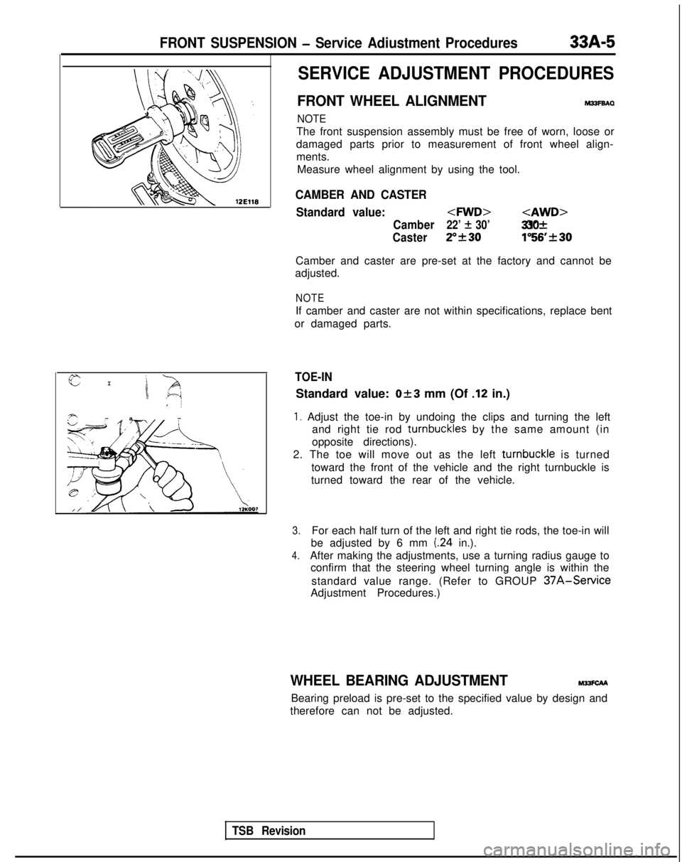
1. Adjust the toe-in by undoing the clips and turning the left and right tie rod turnbuckles
by the same amount (in
opposite directions).
2. The toe will move out as the left turnbuckle
is turned
toward the front of the vehicle and the right turnbuckle is
turned toward the rear of the vehicle.
3.For each half turn of the left and right tie rods, the toe-in will
be adjusted by 6 mm
(24 in.).
4.After making the adjustments, use a turning radius gauge to confirm that the steering wheel turning angle is within the
standard value range. (Refer to GROUP
37A-Service
Adjustment Procedures.)
WHEEL BEARING ADJUSTMENTM?SCAA
Bearing preload is pre-set to the specified value by design and
therefore can not be adjusted.
Page 957 of 1273
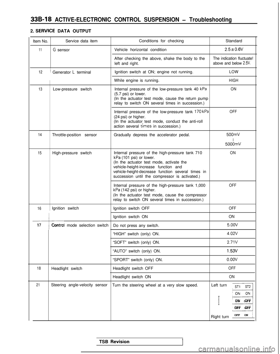
33B-18 ACTIVE-ELECTRONIC CONTROL SUSPENSION - Troubleshooting
2. SERlflCE DATA OUTPUT
Item No. Service data item
Conditions for checking
Standard
11G sensorVehicle horizontal condition2.520.6V
After checking the above, shake the body to theThe indication fluctuate!
left and right.above and below 2.5V.
12/ Generator L terminalIgnition switch at ON; engine not running.LOW
While engine is running.HIGH
13Low-pressure switch
Internal pressure of the low-pressure tank 40 kPaON
(5.7 psi) or lower.
(In the actuator test mode, cause the return pump
relay to switch ON several times in succession.)
Internal pressure of the low-pressure tank
170 kPa
(24 psi) or higher.
(In the actuator test mode, conduct the anti-roll
action several
times in succession.)
OFF
14Throttle-position sensor Gradually depress the accelerator pedal. 500mV
I
5000mV
15High-pressure switch
Internal pressure of the high-pressure tank 710ON
kPa (101 psi) or lower.
(In the actuator test mode, activate the
vehicle-height-increase function and
vehicle-height-decrease function several times in
succession until the compressor is activated.)
Internal pressure of the high-pressure tank 1,000
kPa (142 psi) or higher.
OFF
(In the actuator test mode, cause the compressor
relay to switch ON several times in succession.)
16Ignition switch Ignition switch OFFOFF
I
Ignition switch ONON
17Control mode selection switch
Do not press any switch. 5.oov
“HIGH” switch (only) ON.
4.02V
“SOFT” switch (only) ON.2.71V
“AUTO” switch (only) ON.1.53V
“SPORT” switch (only) ON.o.oov
18Headlight switch Headlight switch OFFOFF
Headlight switch ONON
21Steering angle-velocity sensor
Turn the steering wheel at a very slow speed. Left turnST1 ST2
__I
’ E3
ON OF
F
OFF OFF
Right turn OFF ON
j
TSB Revisio.nI
Page 980 of 1273
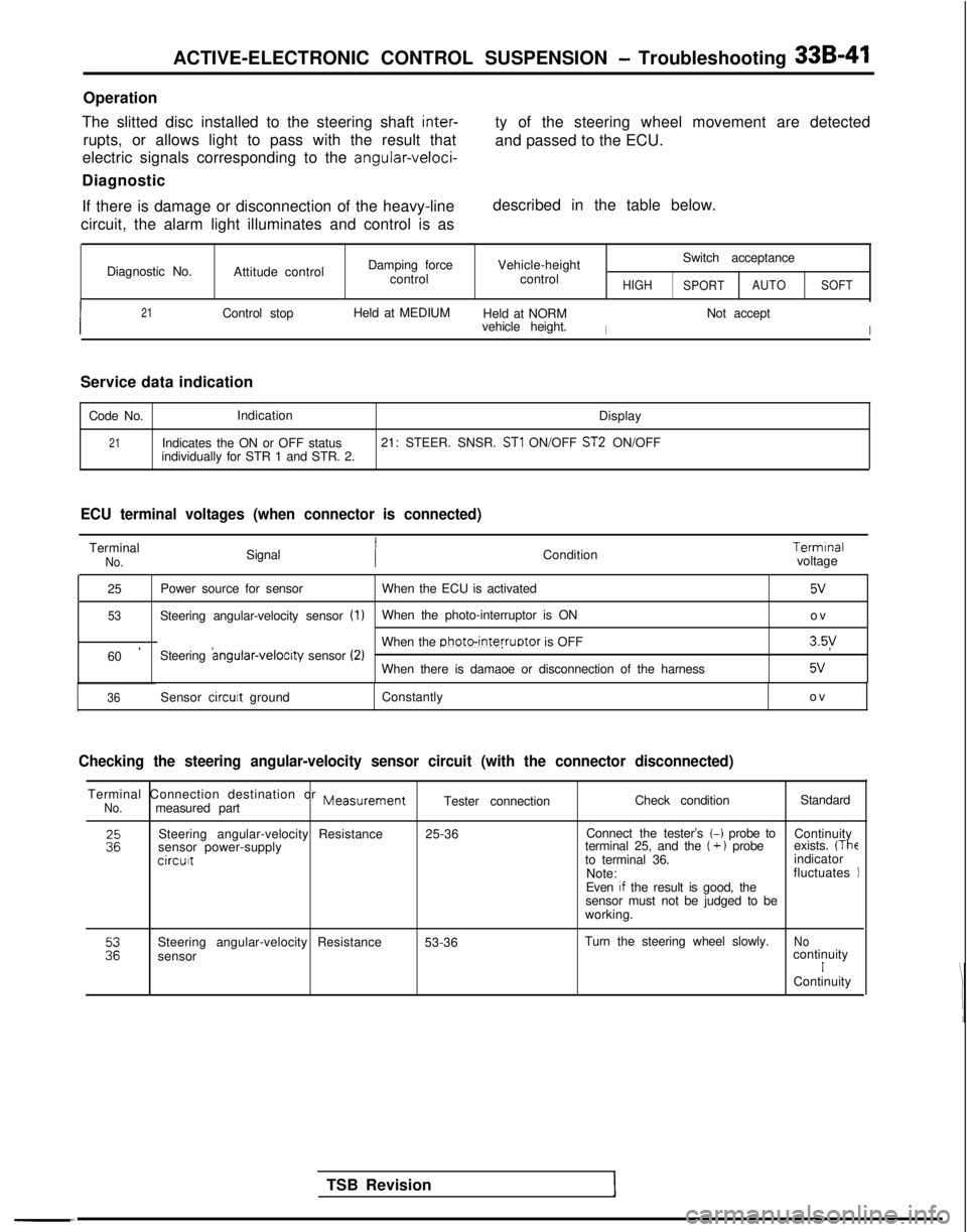
ACTIVE-ELECTRONIC CONTROL SUSPENSION - Troubleshooting 33B-41
Operation
The slitted disc installed to the steering shaft
inter-
rupts, or allows light to pass with the result that
electric signals corresponding to the
angular-veloci-
Diagnostic
If there is damage or disconnection of the heavy-line
circuit, the alarm light illuminates and control is as ty of the steering wheel movement are detected
and passed to the ECU.
described in the table below.
Diagnostic No. Attitude control Damping force
control Vehicle-height
control
HIGH
Switch acceptance
SPORT AUTO
SOFT
I
21Control stop Held at MEDIUM
Held at NORM
I
Not accept
vehicle height.
I
Service data indication
Code No. Indication
Display
21Indicates the ON or OFF status21: STEER. SNSR. ST1 ON/OFF ST2 ON/OFF
individually for STR 1 and STR. 2.
ECU terminal voltages (when connector is connected)
TerminalNo.Signal Condition Termrnal
voltage
25 Power source for sensor
When the ECU is activated
5v
53Steering angular-velocity sensor (1)When the photo-interruptor is ON
o
v
60
’Steering angular-velocrty
sensor (2)When the photo-interruptor is OFF3.5y
When there is damaoe or disconnection of the harness5v
-“.
TSB Revision
36Sensor circuit
ground Constantly ov
Checking the steering angular-velocity sensor circuit (with the connect\
or disconnected)
Terminal Connection destination or MeasurementNo.measured partTester connection
Check condition
Standard
Steering angular-velocity Resistance
sensor power-supply
circut
25-36 Connect the tester’s t-i probe to
Continuity
terminal 25, and the (+ ) probe exists. (Theto terminal 36. indicator
Note: fluctuates
Even
If the result is good, the
sensor must not be judged to be
working.
Steering angular-velocity Resistance
sensor 53-36
Turn the steering wheel slowly.
NocontinuityIContinuity
Page 1026 of 1273
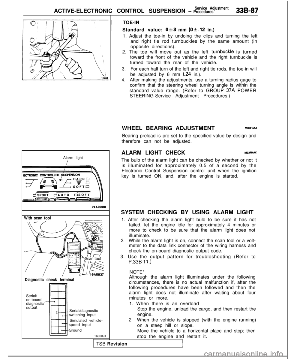
ACTIVE-ELECTRONIC CONTROL SUSPENSIONService Adjustment- Procedures33B-87
Alarm light
With scan tool
Diagnostic check terminal
Serial/
on-board
diagnostic’
outwt
TSB RevisionI
Serial/diagnostic
-switching input
Simulated vehicle-
-speed input
-Ground
16LOO91
!
TOE-IN
Standard value:
Ok3 mm (Of.12 in.)
1. Adjust the toe-in by undoing the clips and turning the left and right tie rod turnbuckles by the same amount (in
opposite directions).
2. The toe will move out as the left turnbuckle
is turned
toward the front of the vehicle and the right turnbuckle is
turned toward the rear of the vehicle.
3.For each half turn of the left and right tie rods, the toe-in will
be adjusted by 6 mm
(.24 in.).
4.After making the adjustments, use a turning radius gage to confirm that the steering wheel turning angle is within the
standard value range. (Refer to GROUP 37A
POWER
STEERING-Service Adjustment Procedures.)
WHEEL BEARING ADJUSTMENT
M33FcAA
Bearing preload is pre-set to the specified value by design and
therefore can not be adjusted.
ALARM LIGHT CHECK
MPFNAC
The bulb of the alarm light can be checked by whether or not it is illuminated for approximately 0.5 of a second by the
Electronic Control Suspension control unit when the ignition
key is turned ON, and, after the engine is started.
SYSTEM CHECKING BY USING ALARM LIGHT 1. After checking the alarm light bulb to be sure it has not failed, let the engine idle for approximately 4 minutes ormore to check to be sure that the alarm light does not
illuminate.
2.While the alarm light is on, connect the scan tool or a volt- meter to the data link connector of the wiring harness and
check the on-board diagnostic output code.
3. Use the output pattern for troubleshooting (Refer to
P.33B-11.)
NOTE*
Although the alarm light illuminates under the following
circumstances, there is no actual malfunction if, after the
following procedures have been followed and then the
alarm light does not illuminate after waiting about four
minutes or more.
1. When there is an overload Stop the engine, unload the cargo, and then restart the
engine.
2.When the vehicle is stopped (with the engine running)
on a steep hill or slope.Move the vehicle to a horizontal place and stop; then
stop the engine and restart it.